MINIWARE DT71 Mini Digital Tweezers User Manual
Safety Statements
Read carefully all the following safety precautions to avoid personal injuries and prevent damage to the device or any products connected to it. Failure to follow these safety instructions could result in personal injuries or risk of fire.
- Please use only the power supply dedicated for this product or certified by your country/region.
- Before connecting and disconnecting DT71’s tips to device under test, please power off the circuit to be tested, and after connecting DT71’s tips correctly, power on and measure the circuit.
- It is recommended to unplug the controller when DT71 is not in use.
- To avoid fire or electric shock, please observe all terminal ratings and marking instructions to avoid damage to the device. Before connecting DT71, please read the product manual or product label for information about the rated values;
- After the power is turned on, do not touch the exposed connectors and components. Do not use it when you suspect thot the product is malfunctioning. Please contact after-soles service for testing, maintenance, adjustment or parts replacement;
- Static electricity con cause damage to DT71, and measuring should be mode in anti-static areas if possible. Before connecting DT71 to the device under test, the inner and outer conductors should be grounded briefly to discharge static electricity.
- Please keep DT71 surface clean and dry; do not operate in humid, inflammable and explosive environment.
Warnings
Please do not disassemble DT71 controller or test arms. Once disassembled, it cannot be repaired!
Liability Statement:
Any damage of the product or losses related to the product damage, if it’s mon-caused, or assumed to be mon-caused, the liability will belong to the user. The user is responsible for any damage or loss caused by unauthorized disassembly or modification of the product.
Product Introduction
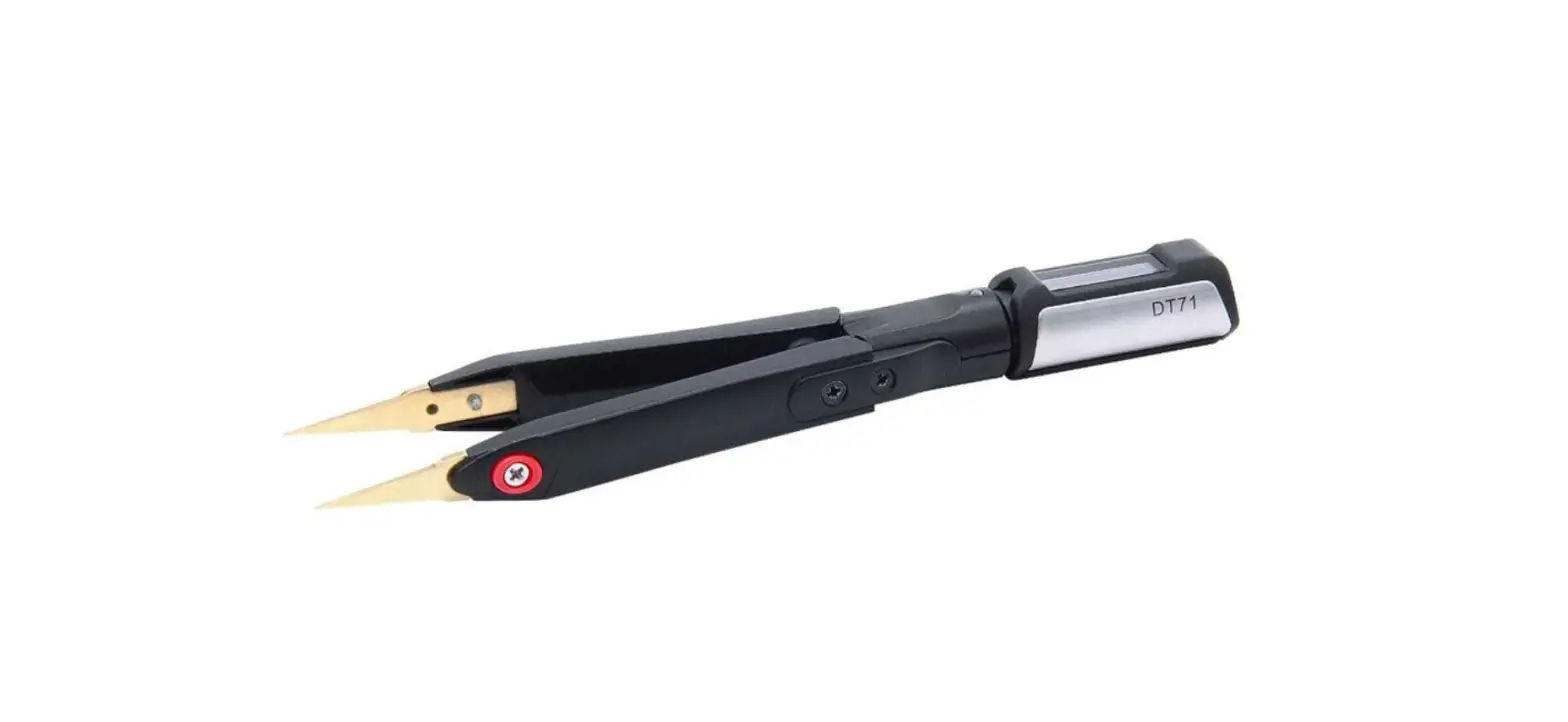
DT71 Mini Digital Tweezers is a multi-function measure tool with a fully differential input and built-in signal generator. DT71 has a unique ternary structure, which con be split into a controller, test arms and tweezer tips, flexible in replacement and combination. DT71 uses thickened gold plated tweezer tips, which con be replaced according to the application scenario. It con measure various devices such as resistor, capacitor, inductor, voltage, frequency, diode, etc. to help users quickly identify components. The built-in micro signal generator of DT71 con output a variety of signals, providing a perfect solution for the debugging and maintenance of complex electronic systems and the classification and detection of discrete chip components.
Appearance
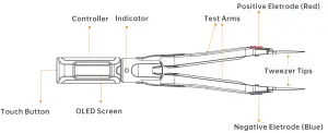
Introduction
DT71 Mini Digital Tweezers is a new concept portable LCR tester, which con automatically identify the type of electronic components and actively select the appropriate range for measure; the built-in signal generator con output a variety of required signals for electronic system debugging and maintenance.
 7 measurement types: resistance, inductance, capacitance, voltage, frequency, diode
- Automatic identification of components, Measure primary and secondary parameters
- Micro signal generator
- Controller can be rotated 560°, providing different viewing angles
- Smart Recognition, automatically recognize left and right hand mode
- Sleep mode, pick up to woke up
Parameters
| Power interface | 5.5mm audio | |
| Size | Controller | 47mm |
| Test arms | 106mm | |
| Weight | 22g | |
| Working temperature | 10-50°C | |
| Working humidity | 10-90%RH | |
| Charging time | 2 hours | |
| Operation time | 10 hours (in continuous use) | |
Installation And Charging
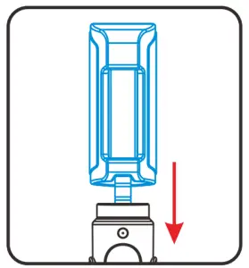
Installation
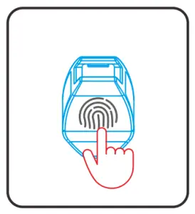
- Fully insert the 3.5mm audio plug of DT71 controller into the socket of the test arms. After the correct insertion, the screen will display the bootup icon and firmware version, and then enter user interface;

Display
Bootup icon Firmware version - Tap the touch button to select measure mode for use.

Display


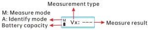
Button and menu
DT71 has no physical buttons, only a hidden touch button on the top of the controller. Users con switch functions and modes by topping the touch button.
| Operating | Function | |
 | Long press | Switch submenu of measure/automatic identification/signal generator/calibration mode |
| Single top | Switch menu options | |
Menu:
| Submenu | Menu Definition | Options | Options Definition | Measuring Range |
| Measure | Measure mode; default | Rx:— | Resistance | 0.1C -2M C |
| Dx:— | Diode | 0.1V-3v | ||
| Cx:— | Capacitance | o.1pF-400uF | ||
| Lx:— | Inductance | 1uH-50mH | ||
| Fx:— | Frequency | 10HZ-20MHZ | ||
| Vx:— | Voltage | 1mv-4OV |
| Identify | Automatic identification mode | Screen will display ”A” on lower left corner; Con automatically measure resistance/ inductance/capacitance /diode | ||
| Signal Gen | Signal generator mode | SINE 10KHz | Output sine wove, default 10KHz | For frequency modification options, see configuration file description P13 |
| NOISE 100KHz | Output noise wove, default 100KHz | |||
| USER 2KHz | Output user-defined wave, default 2KHz | |||
| PULSE 10KHz | Output pulse wove, default 10KHz | |||
| Calibration | Calibration mode | Calibration #0 Close Tips Pis! | Closed (short-circuit) tweezer tips | Please refer to P12 |
| Calibration #1 Open Tips Pls! | Open (open-circuit) the tweezer tips |
How to charge
Insert the 3.5mm mole plug of DT71’s dedicated cable into test arms, and connect a DCSV power source to charge it. The charging indicator will be on (red) when charging, and off when fully charged.
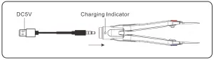
Warnings: DO NOT charge DT71 controller
Automatic sleep and wake up
DT71 has on automatic sleep function, when DT71 remains static for 60 seconds (factory setting), it will automatically enter sleep mode; When you need to use it again, pick up DT71 to woke it up to enter user interface.
Measure
Preparation before measuring
Before measuring, please connect DT71 controller to test arms, or wake up DT71 from sleep mode. When the screen displays, select the correct measure mode to start measuring.
Measure parameters and accuracy:
| Measure Type | R | D | C | L | F | v | |||||
| Resistance | Diode | Capacitance | Inductance | Frequency | Voltage | ||||||
| Range | 0.10 – 1000C | 1K0 -2 OOOKO | 0.1V- 3V | 0.1pF- 100OpF | 0.001uF- 400uF | 1uH – 1000uH | 1mH- 50mH | 10Hz- 1000Hz | 1kHz-20 000KHz | 1mV- 100mV | 0.1V- 40V |
| Resolution | 0.10 | 1KC | 0.1V | 0.1pF | 0.001uF | 1uH | 1mH | 10Hz | 1KHz | 1mV | 0.1V |
| Accuracy | 0.5%•2 | 0.5%+2 | 1% | 2%+5 | 2%+5 | 5%+3 | 5%+5 | 0.1%+3 | 0.1%+3 | 2%+5 | 1%+5 |
The test data comes from laboratory environment and is for reference only.
True error range=*(reading*accuracy + corresponding resolution*value)
Note: Maximum absolute input voltage: -5V – SOV; Input resistance: 1M G.
Manual Measure Mode
Resistance

- Top DT71’s touch button to switch to resistance measure mode;
- Clamp tweezer tips in the two poles of resistance;
- The screen will display the resistance value.
Frequency

- Top DT71’s touch button to switch to frequency measure mode;
- The positive electrode (red) of the tweezer tips connects to the signal positive, and the negative electrode (blue) to the signal ground; there will be no value if connected in reverse
- The screen will display the frequency value
Inductance
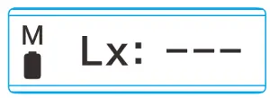
- Top DT71’s touch button to switch to inductance measure mode;
- Clamp tweezer tips in the two poles of inductance;
- The screen will display the inductance value.
Capacitance

- Top DT71’s touch button to switch to capacitance measure mode
- Clamp tweezer tips in the two poles of capacitance
- The screen will display the capacitance value.
Diode

- Tap DT71’s touch button to switch to diode measure mode;
- Clamp tweezer tips in the two poles of diode. The positive electrode (red) of the tweezer tips to the positive of the diode, and the negative electrode (blue) of the tweezer tips to the negative of the diode;
- The screen will show the diode forward voltage drop.
Voltage:

- Tap DT71’s touch button to switch to voltage measure mode;
- The positive electrode (red) of the tweezer tips connects to the high potential, and the negative electrode (blue) to the low potential;
- The screen will display the voltage value.
The screen will display “Negative” if the positive and negative tips of the DT71 are reversed. Please adjust and measure again.
When the measured object is powered on, DO NOT insert or remove DT71 controller.
Automatic Identification Mode
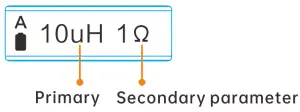
- Long press DT71’s touch button to switch to automatic identification mode (Identify); DT71 con automatically identify inductor ,capacitor, resistor, diode;
- The screen will display the primary parameters and secondary parameters of the measured object
Signal Output
Signal output types:
| Type | SINE | NOISE | USER | PULSE |
| Sine Wove | Noise Wove | User-defined Wove | Pulse Wove | |
| Frequency | For frequency modification options, see configuration file description p13 | |||
Signal Connector

- Long press DT71’s touch button to switch to signal generator mode (Signal Gen);
- Top the touch button to switch sine wove/noise wove/user-defined wove/pulse wove.
User-Defined Wave

- Top DT71’s touch button to switch to “USER“ signal output;
- The output waveform con be defined in the DFU configuration file, please refer to P14,
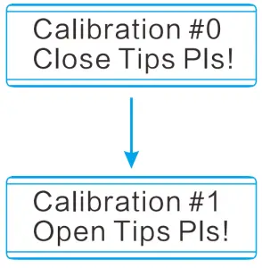
Calibration
Zero Calibration
- Long press DT71’s touch button to switch to calibration mode (Calibration);
- Keep the tweezer tips closed and short circuit until the screen prompts the next step;
- Open the tweezer tips and keep it open until the screen prompts the next step;
- After the open calibration is successful, the screen will prompt whether to save the calibration data, top the touch button to confirm and save.
* If you mistakenly enter calibration mode, long press the touch button to exit.
Accurate Calibration
For accurate calibration, please visit www.miniwore.com.cn and download the DT71 calibration file, and operate according to the instructions
Config File
Insert DT71 controller into the Data Cable’s 5.5mm female socket (no need to connect test arms) , connect the Data Cable to your PC via USB Type-C cable; a 8 character string removable hard disk will appear on your PC. Open the CAL.INI configuration file in the removable disk and set the parameters.
Parameter Setting
| Parameter | Definition | Setting Range |
| SLEEP TIME=60 | Sleep time | 30-999 (Second) |
| DISPLAY DIRECTION=4 | Left/Right hand mode | 0: Right hand mode, 5: Left hand mode 4: Automatic recognition |
| OLED BRIGHTNESS=2 | Display brightness | 0-10 |
| TSC SEN=1 | Touch button sensitivity | 0:Not sensitive, 1:Normal, 2:Sensitive |
| SINE FREQ OPT=0 | Sine wove signal frequency parameters | 0:1OKHz, 1:5KHz, 2:2KHz, 5:1KHz, 4:500Hz, 5:200Hz |
| NOISE FREQ OPT=1 | Noise signal frequency parameter | Currently the noise signal only supports 100KHz |
| USER FREQ OPT=2 | User-defined signal frequency parameters | 0:1OKHz, 1:5KHz, 2:2KHz, 5:1KHz, 4:500Hz, 5:200Hz |
| PULSE FREQ OPT= 3 | Pulse signal frequency selection parameter | 0:100KHz, 1:50KHz, 2:20KHz, 5:10KHz, 4:5KHz, 5:2KHz, 6:1KHz, 7:500Hz, 8:200Hz |
Restore Factory Setting
Open the CAL.INI config file, delete all data, enter “load default” and save it to restore the factory settings.
User-Defined Wave Setting
USER WAVEFORM = {
0x7FF, 0x87F, 0x8FF, 0x97E, 0x9FC, 0xA77, 0xAF0, 0xB66, 0xBD9, 0xC48,
0xCB2, 0xD18, 0xD78, 0xDD3, 0xE29, 0xE77, 0xEC0, 0xF01, 0xF5C, 0xF6F,
0xF9A, 0xFBE, 0xFDA, 0xFEE, 0xFFA, 0xFFE, 0xFFA, 0xFEE, 0xFDA, 0xFBE,
0xF9A, 0xF6F, 0xF3C, 0xF01, 0xEC0, 0xE77, 0xE29, 0xDD3, 0xD78, 0xD18,
0xCB2, 0xC48, 0xBD9, 0xB66, 0xAF0, 0xA77, 0x9FC, 0x97E, 0x8FF, 0x87F,
0x7FE, 0x77E, 0x6FE, 0x67F, 0x601, 0x586, 0x50D, 0x496, 0x424, 0x5B5,
0x54B, 0x2E5, 0x285, 0x22A, 0x1D4, 0x186, 0x13D, 0x0FC, 0x0C1, 0x08E,
0x063, 0x03F, 0x023, 0x00F, 0x005, 0x000, 0x003, 0x00F, 0x023, 0x03F,
0x063, 0x08E, 0x0C1, 0x0FC, 0x13D, 0x186, 0x1D5, 0x22A, 0x285, 0x2E5,
0x54B, 0x3B5, 0x424, 0x497, 0x50D, 0x586, 0x601, 0x67F, 0x6FE, 0x77E,
0x000, 0x000, 0x000, 0x000, 0x000, 0x000, 0x000, 0x000, 0x000, 0x000,
0x000, 0x000, 0x000, 0x000, 0x000, 0x000, 0x000, 0x000, 0x000, 0x000,
0x000, 0x000, 0x000, 0x000, 0x000, 0x000, 0x000, 0x000, )
Note
- Use hexadecimal number 0x000-0xFFF to represent 0-3V signal waveform;
- The output waveform only loads the first 100 points of valid data; red font modification is invalid.
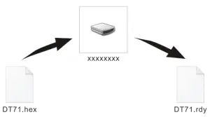
Firmware Upgrade
- Visit www.miniwore.com.cn to download the appropriate DT71 firmware to your PC.
- Insert DT71 controller into the Data Cable’s 3.5mm female socket (no need to connect test arms), connect the Data Cable to your PC; a 8-character string removable hard disk will appear on your PC, entering DFU setting mode.
- Copy the .hex firmware to the root directory of that disk. After the extension of the firmware changes from “.hex” to “.rdy”, restart DT71, thus the firmware is upgraded.
Standard Service
One year of free warranty will be provided, if the damage was not caused by false manipulation by the user. Please contact your seller for warranty details. Tweezer tips ore consumables, once it’s used, no replacement will be provided
Legal Statements
Disposal
![]() Do not dispose this product with domestic waste.
Do not dispose this product with domestic waste.
- This device complies with the WEEE Directive (this additional product label indicates that this electronic product must not be disposed of in household waste).
- Handling and recycle: Disposal of the product shall be manipulated according to lows and regulations in your area.
Statement of fulfilling FCC standard
![]() This device fulfills port 15 of the FCC regulations. Device must fulfill below 2 conditions:
This device fulfills port 15 of the FCC regulations. Device must fulfill below 2 conditions:
- Device must not generate interference;
- Device must be able to resist any interferences on it, including interferences that could cause dangerous manipulation.
Statement of fulfilling CE standard
![]() This product with CE logo on it fulfills related Euro Union laws and regulations.
This product with CE logo on it fulfills related Euro Union laws and regulations.


