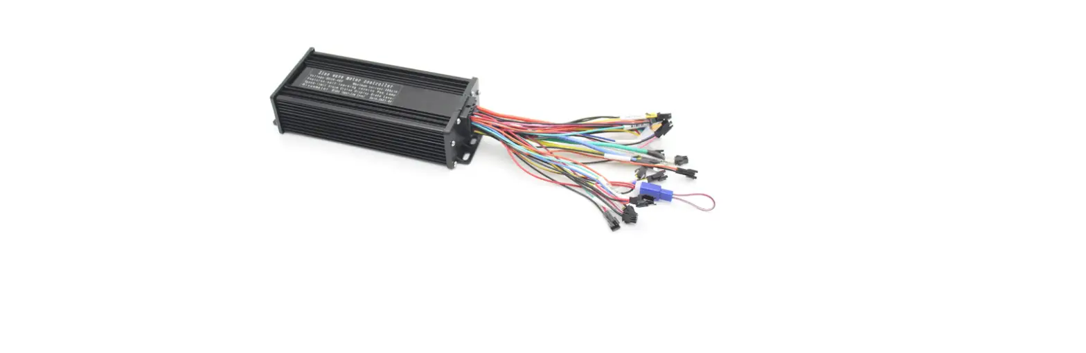
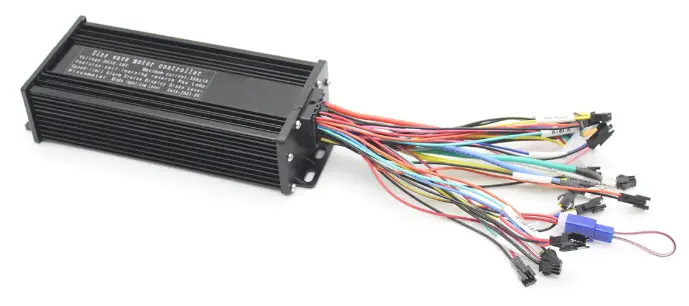
HALLOMOTOR IP65 36V-52V 1000W-1500W Sine Wave ebike Controller
Very Important Notice:
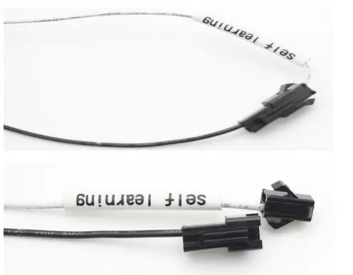
Before you connect controller with your motor wheel, please disconnect self-learning plugs (No.12):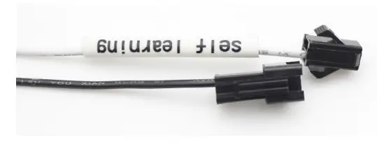
How to match controller and motor for first use:
- Lift your motor wheel off ground (very important)
- Connect Self-learning plug 6-8 seconds
- You will see motor wheel rotate slowly
- Please check whether rotation direction is correct
- If correct direction, then keep 6-8 seconds, then disconnect
- If reverse direction, then disconnect and plug again till get correct rotation direction, then keep 6-8 seconds, then disconnect
- Motor and Controller Pairing finished

Why 3-mode Controller
- Support Hall Sensor Mode (Sine Wave Mode)
- Support Non-Hall Mode (If your motor hall sensor burned or not match, controller will still work in square wave mode)
- Self-learning Function: Even wrong 3-phase combination between motor and controller, doesn’t matter, above self-learning process can correct it!
Connection Diagram
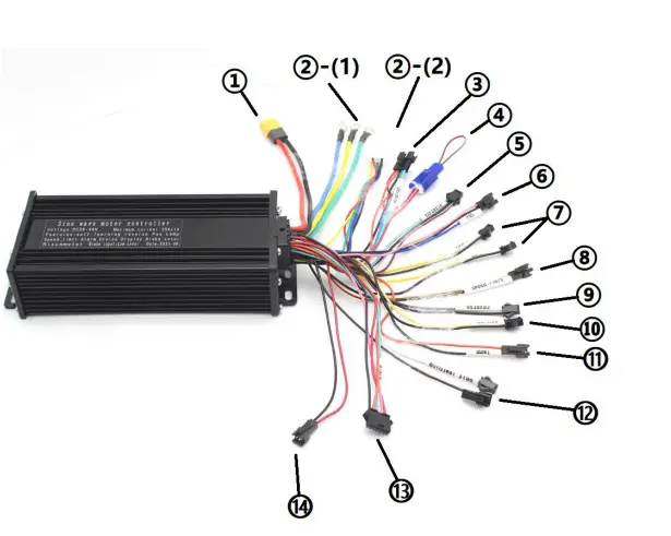
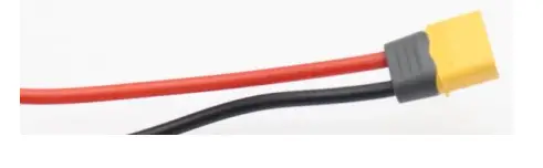
- Power Supply Cable: XT60 Male Plug
Controller Side XT60 Male Red (Positive) Black (Negative)
Definition
Power Input Connector Positive Pole Negative Pole
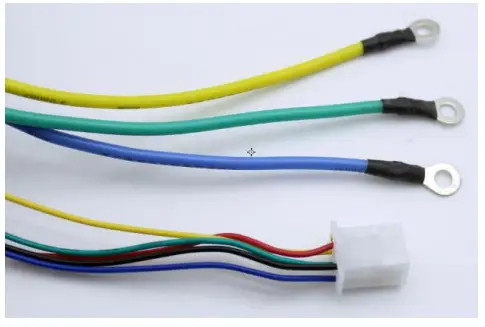
- Motor Cable Connection (3-Phase + hall sensor):
- Motor 3-Phase: “O” rings, use yellow “O” ring connection box
- Controller Side 3-“O” Rings Yellow
- Green
- Blue
- Definition
- Motor 3-Phase Connector
- Motor Phase-A Motor Phase-B
- Motor hall sensor: White DJ7061-2.8-21 Female Plug
- Controller Side DJ7061-2.8-21 Female Red
- Black
- Yellow
- Green
- Blue
- Definition
- Motor Hall Sensor Connector 5V+ Positive
- Negative
- Hall Sensor Signal
- Hall Sensor Signal

- If you want motor rotate as reverse direction with original speed, then just exchange two wires of phase and hall sensor wires:
- 3-Phase Wire: exchange Yellow and Blue
- Hall Sensor Wire: exchange Yellow and Green
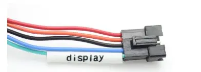
- LCD Display Connection: Black SM-5A Male Plug
- Controller Side SM-5A Male Red
- Pink
- Black
- Blue
- Green
- Definition
- LCD Display Connector Power input positive Electric Lock
- Negative
- TxD

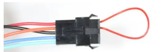
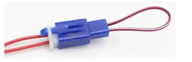
- If you don’t want to use LCD, please just plug the connector as follow photo (connect red and pink):

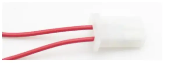
- Electric Lock: White 2.8B-2 Female Plug
- Controller Side 2.8B-2 Female
- Red Red

- Definition
- Electric Lock Connector
- If you use your own throttle and without electric lock, then please just connect jumper plug as follow photo:

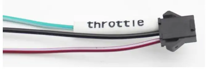
- Throttle Connection: Black SM-3Y Female Plug
- Controller Side SM-3Y Female Dark Red Black
- Green(Signal)
- Definition Throttle Connector Positive
- Negative
- Hall Sensor Signal

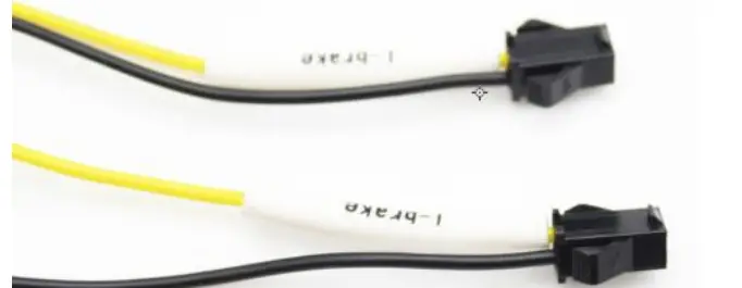
- Brake Levers Connection: 2 x Black SM-2Y Female Plugs
- Controller Side 2x SM-2Y Female Black
- Yellow
- Definition
- Brake Connector Negative
- Signal

- PAS Connection: Black SM-3A Male Plug
- Controller Side SM-3A Male Pink
- Black
- Blue(Signal)
- Definition
- PAS Connector Positive
- Negative
- Hall Sensor Signal

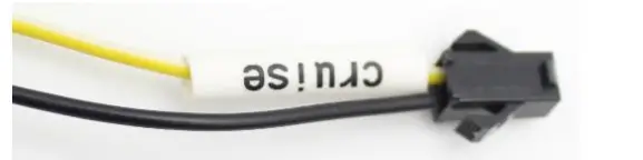
- Cruise Plug Connection: Black SM-2Y Female Plug
- Controller Side Definition
- SM-2Y Female Cruise Connector Black
- Yellow
- Without jumper plug/Switch: Without cruise function

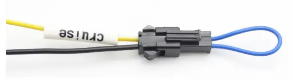
- With jumper plug connected: Cruise function is activated (if you keep throttle at definite fixed speed 6 seconds will activate cruise function)

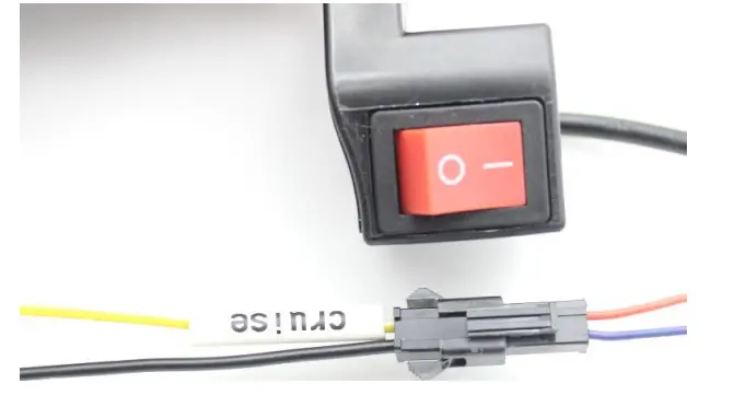
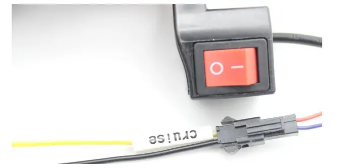
- With switch (Switch on/off):
- Without jumper plug/Switch: Without cruise function
- Switch on: Cruise function is activated (if you keep throttle at definite fixed speed 6 seconds will activate cruise function)

- Switch off: Without cruise function

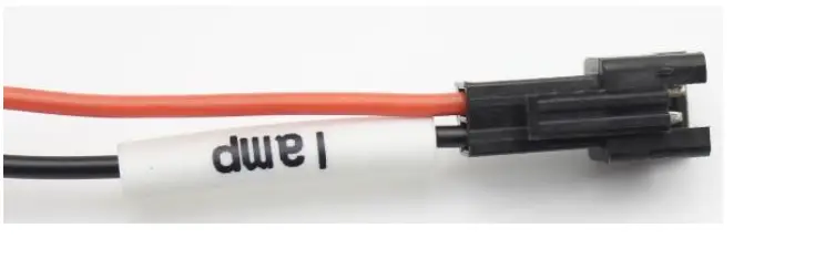
- Head Light Connection: Black SM-2A Male Plugs
- . Black SM-2A Male Plug: head light will be controlled by LCD Display, 36V or 48V output (according to battery you use), max current 150mA, max power 7W. Otherwise will be burned.
- Controller Side SM-2A Male Orange
- Black
- Definition
- Headlight Connector
- Your head light positive wire Your head light negative wire

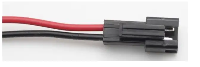
- Black SM-2A Male Plug: head light will be controlled by switch, you can connect switch to control your light, 36V or 48V output (according to battery you use), can take 2A current, 100W light.
- Controller Side SM-2A Male Red
- Black
- Definition
- Power Output Connector
- Your switch/head light positive wire Your head light negative wire

- . Black SM-2A Male Plug: head light will be controlled by LCD Display, 36V or 48V output (according to battery you use), max current 150mA, max power 7W. Otherwise will be burned.
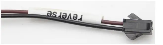
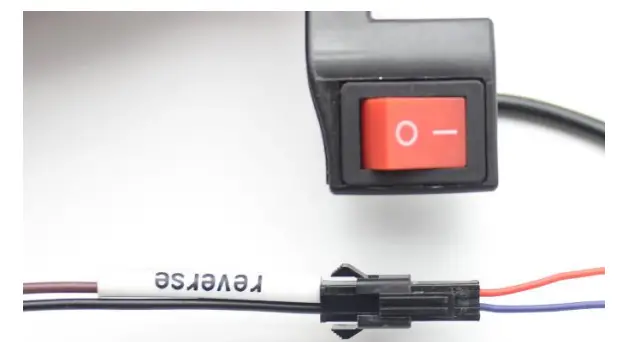
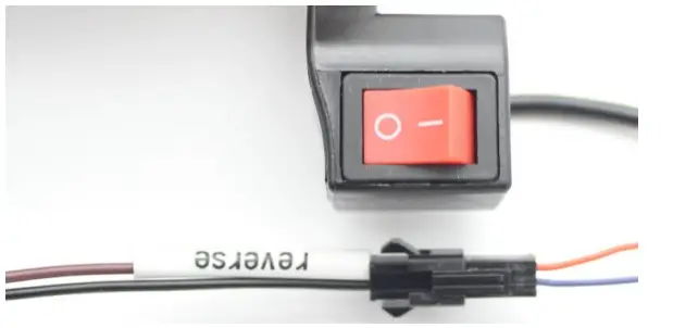
- Reverse Function: Black SM-2Y Female Plug
- Controller Side SM-2Y Female
- Definition
- Reverse Jumper/Switch Connector
- Brown
- Black
- Without jumper plug/Switch: Rotate forward

- With jumper plug connected: Rotate backward

- With Switch (Switch on/off): Switch on: Rotate backward; Switch off: Rotate forward

- Without jumper plug/Switch: Rotate forward
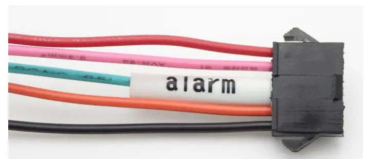
- Alarm Function: Black SM-6Y Female plug
- Controller Side SM-6Y Female Red
- Pink
- Green
- Orange
- Black
- Definition
- Alarm Connector Power Positive (+)
- Wheel Movement Alarm Alarm Signal
- Electric Lock
- Power Negative (-)

- Motor 3-Phase: “O” rings, use yellow “O” ring connection box