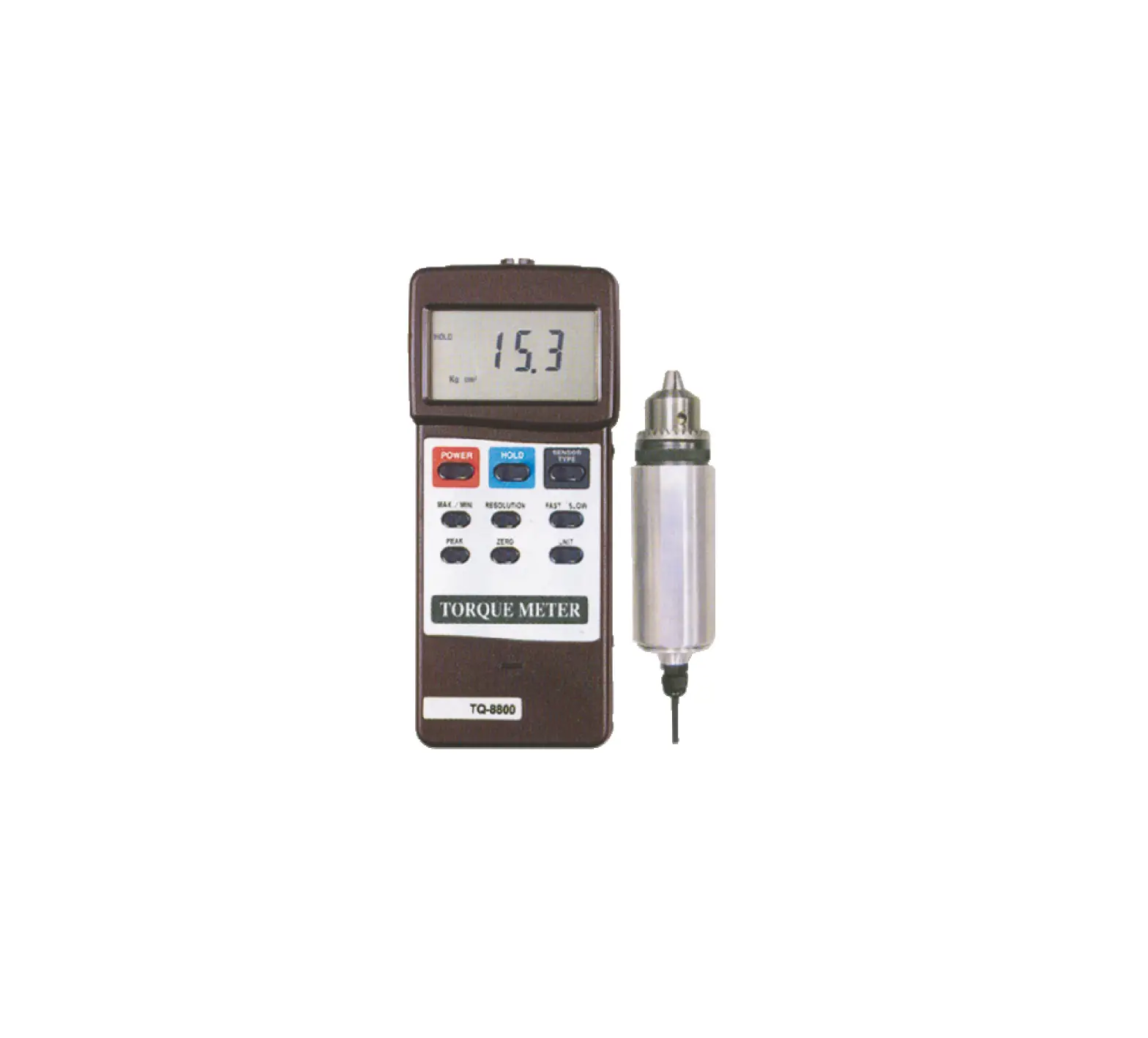
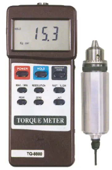
LUTRON TQ-8800 Torque Meter
PLEASE READ THIS MANUAL CAREFULLY BEFORE OPERATION
FEATURES
- Professional torque meter with 15 Kgf-cm torque probe, full set.
- 3 kind display unit select button of Kgf-cm, LBf-inch and Newton-cm on the front panel.
- Data hold button to freeze the desired reading.
- Peak measurement to hold the peak value.
- Selecting the high resolution or low resolution.
- Fast or Slow sampling time selecting by push button.
- Record Maximum and Minimum readings with recall.
- RS 232 computer interface.
- Super large LCD display, easy readout.
- Microcomputer circuit, high performance.
- Separate torque probe, easy operation.
- Auto power off saves battery life.
- Built-in low battery indicator.
- Heavy duty & compact housing case.
- Complete set with the hard carrying case.
SPECIFICATIONS
General Specifications
| Accuracy | ( 1.5 % + 5 d ) | |
| Resolution | High resolution 0.01 Kgf-cm 0.01 LBf-inch 0.1 N-cm * N = Newton | |
| Low resolution 0.1 Kgf-cm 0.1 LBf-inch 1 N-cm * N = Newton | ||
| Sensor | Exclusive torque sensor. | |
| Circuit | Exclusive microcomputer circuit. | |
| Data hold | Freeze the desired reading. | |
| Peak hold | To hold the peak value. | |
| Memory | Maximum & Minimum value. | |
| Overload capacity | 22.5 Kgf-cm max. 19.53 LBf-inch max. 220.1 N-cm max. | |
| Power off | Auto shut off, saves battery life, or manual off by push button. | |
| Sampling time | Fast/Slow select. Fast : Approx. 0.125 second. Slow : Approx. 0.334 second. | |
| Data output | RS 232 serial output. | |
| Operating temperature | 0 to 50 ( 32 to 122 ). | |
| Operating humidity | Less than 80% RH. | |
| Power supply | Alkaline or heavy duty typeDC 9V battery, 006P, MN1604 (PP3) or equivalent. | |
| Power consumption | Approx. DC 12 mA. | |
| Weight | Meter | 225 g ( 0.50 LB ). |
| Probe | 665 g ( 1.46 LB ). | |
Display Unit/Max. range/Resolution
| Unit | Max. range | High resolution |
| Kg-cm | 15 Kgf-cm | 0.01 Kgf-cm |
| LB-inch | 13.02 LBf-inch | 0.01 LBf-inch |
| Newton-cm | 147.1 N-cm | 0.1 N-cm |
| Unit | Max. range | Low resolution |
| Kg-cm | 15.0 Kgf-cm | 0.1 Kg-cm |
| LB-inch | 13.0 LBf-inch | 0.1 LB-inch |
| Newton-cm | 147 N-cm | 1 N-cm |
* N = Newton
FRONT PANEL DESCRIPTION
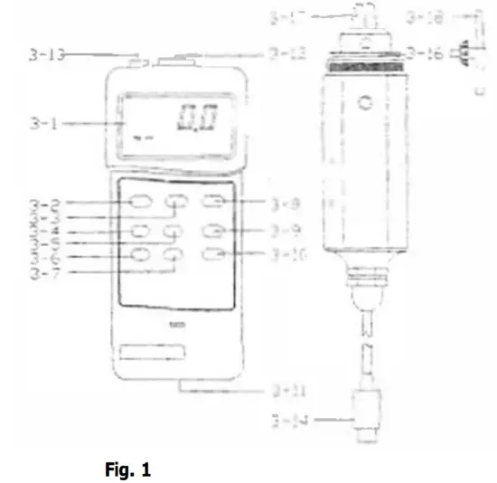
3-1 Display
3-2 Power Button /Cover
3-3 Hold Button sac
3-4 ” Max./Min. ” Button
3-5 Unit Button Terminal
3-6 Peak Button
3-7 Resolution Button
3-8 Sensor Type Button
3-9 Zero Button
3-10 Fast/Slow Button
3-11 Battery Compartment
3-12 Sensor Input Socket
3-13 RS-232 Output
3-14 Sensor Cable Plug
3-15 Torque Sensor Body
3-16 Gear
3-17 Cramp
3-18 Pinion
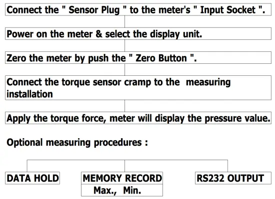
MEASURING PROCEDURE
- Plug in the ” Sensor Cable Plug ” ( 3-14, Fig. 1 ) to meter’s ” Sensor Input Socket ” ( 3-12, Fig. 1 ).
- Power on the meter by push the ” Power Button ” ( 3-2, Fig. 1 )
- Push the ” Sensor Type Button ” ( 3-8, Fig 1 ) to check if the meter’s sensor type is same as the external torque sensor.
Push the ” Sensor Type Button “, the LCD will show ” 15 Kg cm “. - Unit Button
Push the ” Unit Button ” ( 3-5, Fig. 1 ) to select the unit Kgf-cm, LBf-inch or N-cm ( Newton-cm ). - Resolution Button
Push the ” Resolution Button ” ( 3-7, Fig. 1 ) to select the High resolution or Low resolution.
Select high resolutionDisplay unit Resolution Kg cm 0.01 Kgf-cm LB inch 0.01 LBf-inch N cm 0.1 N-cm Select low resolution
Display unit Resolution Kg cm 0.1 Kg-cm LB inch 0.1 LB-inch N cm 1 N-cm - Fast/Slow Button
The ” Fast/Slow Button ” ( 3-10, Fig. 1 ) is used to select the fast sampling time or slow sampling time.
* Fast sampling time, display will show the ” F ” indicator.
* Slow sampling time, display will show the ” S ” indicator. - To connect the ” Cramp ” ( 3-17, Fig. 1 ) to the measured installation and use the ” Opinion ” ( 3-18, Fig. 1 ) to lock the ” Gear ” ( 3-16, Fig. 1 ). Ref. Fig. 2 & Fig. 3.
- Zero Button
Before the measurement, if the meter not show zero value, it can push the ” Zero Button ” ( 3-9, Fig. 1 ) to tare the display value, the LCD will change to zero value. - Apply the torque force, the LCD will show the measured torque value.
- Peak hold
During the measurement, push the ” Peak Button ” ( 3-6, Fig. 1 ), the LCD will show the ” PEAK ” indicator & the display will hold the peak value.
Remark :
Under the peak hold function, the sampling time will define to ” Fast sampling ” & the disiplay will show the ” F ” indicator. - Data Hold
During the measurement, pushing the ” Hold Button ” ( 3-3, Fig. 1 ) will freeze the measured value & display will indicate ” HOLD ” symbol. Push the ” Hold Button ” again to release the data hold function. - Data Record ( Maximum, Minimum reading )
* The DATA RECORD function displays the maximum and minimum readings. To start the DATA RECORD function, press the ” Max./Min. Button ” ( 3-4, Fig. 1 ) once. ” REC ” symbol will appear on the LCD display.
* With the ” REC ” symbol on the display :
(a) Push the ” Max./Min. Button ” ( 3-4, Fig. 1 ) once, the ” Max ” symbol along with the maximum value will appear on the display.
(b) Push the ” Max./Min. Button ” again, the ” Min symbol along with the minimum value will appear on the display.
(c) To exit the memory record function, push the ” Max./Min. ” button continuously at least 2 seconds.
The display will revert to the current reading. - For quick measurement, follow the procedures shown below :
Main procedures :
Power management :

(Not activated during Memory Record Selection)
AUTO POWER DISABLE
The instrument has built-in ” Auto Power Shut-off ” in order to prolong battery life. The meter will switch off automatically if none of the buttons are pressed within approx. 10 min.
To disable this feature, Select the memory record function during measurement, by pressing the ” Max./Min. ” button ( 3-4, Fig. 1 ).
RS232 PC SERIAL INTERFACE
The instrument features an RS232 output via 3.5 mm Terminal ( 3-13, Fig. 1 ).
The connector output is a 16 digit data stream which can be utilized to the user’s specific application.
An RS232 lead with the following connection will be required to link the instrument with the PC serial input.
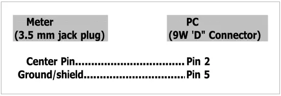
The 16 digit data stream will be displayed in the following format :

Each digit indicate the following status :
| D0 | End Word | ||
| D1 & D8 | Display reading, D1 = LSD, D8 = MSD For example : If the display reading is 1234, then D8 to D1 is : 00001234 | ||
| D9 | Decimal Point(DP), position from right to the left 0 = No DP, 1= 1 DP, 2 = 2 DP, 3 = 3 DP | ||
| D10 | Polarity 0 = Positive 1 = Negative | ||
| D11 & D12 | Annunciator for Display | ||
| Kg cm = 81 | LB inch = 82 | N cm = 83 | |
| D13 | 1 | ||
| D14 | 4 | ||
| D15 | Start Word | ||
RS232 FORMAT : 9600, N, 8, 1
BATTERY REPLACEMENT
- When the left corner of LCD display show ” “,
It is necessary to replace the battery. However, within specification measurement may still be made for several hours after low battery indicator appears before the instrument become inaccurate. - Slide the Battery Cover ( 3-11, Fig. 1 ) away from the instrument and remove the battery.
- Install a 9 V battery ( heavy duty ) and replace the cover.
OTHER OPTIONAL ACCESSORIES
| RS-232 cable, Model : UPCB-01 | RS-232 cable, used for connecting the torque meter & the computer. |
| Application Software ( Window version ) SW-U101-WIN | After setup whole hardware Torque meter + RS-232 cable + Computer + software ( SW-U101-WIN ) whole system can execute as a data logger, data recorder…. record data can be retrieved for EXCELL, ACCESS, LOTUS-123….. |


