DAUDIN iO-GRIDm Relay Output Module User Manual
Relay Output Module List
| Product No. | Description | Remarks |
| GFAR-RM11 | 8-Channel relay module, grounded | |
| GFAR-RM21 | 4-Channel relay module, grounded |
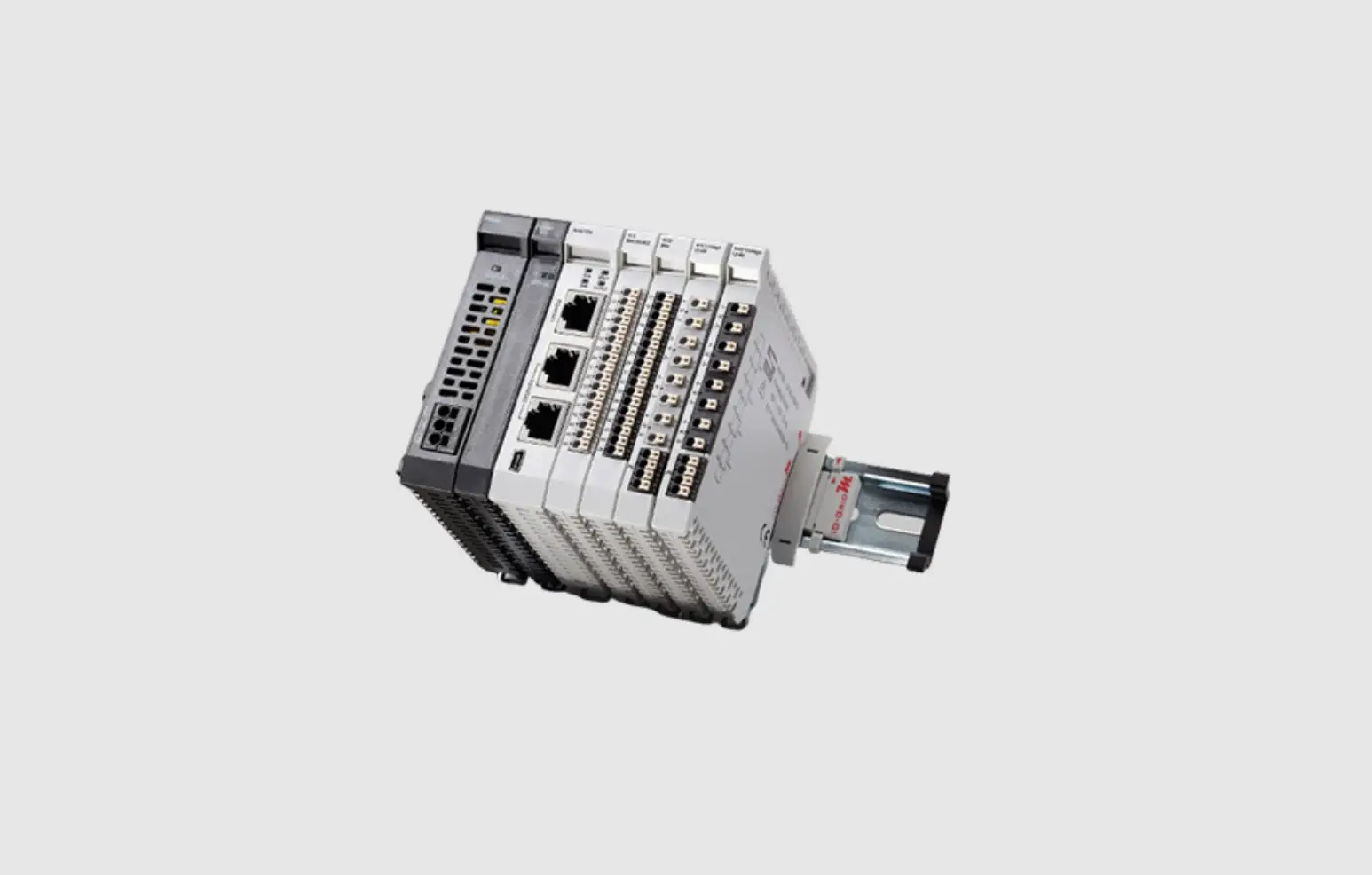
Product Description
The GFAR relay module series is designed specifically for industrial applications. It has a 4-channel and 8-channel model, both can control AC/DC load through communication
![]() Caution (ATTENTION):
Caution (ATTENTION):
- THIS DEVICE IS FOR INDOOR USE ONLY, DON’T PUT OR USE IT IN HIGH TEMPERATURE AND HIGH MOISTURE ENVIRONMENT.
- AVOID FALLING AND BUMPING OTHERWISE THE ELECTRICAL COMPONENTS WILL BE DAMAGED.
- DON’T TRY TO DISASSEMBLE OR OPEN THE COVER UNDER ANY CIRCUMSTANCE IN ORDER TO AVOID DANGER.
- IF THE EQUIPMENT IS USED IN A MANNER NOT SPECIFIED BY THE MANUFACTURER, THE PROTECTION PROVIDED BY THE EQUIPMENT MAY BE IMPAIRED.
- THE INSTALLATION THAT THE SAFETY OF ANY SYSTEM INCORPORATING THE EQUIPMENT IS THE RESPONSIBILITY OF THE ASSEMBLER OF THE SYSTEM.
- USE WITH COPPER CONDUCTORS ONLY. INPUT WIRING: MINIMUM 28 AWG, 85°C, OUTPUT WIRING: MINIMUM 28 AWG, 85°C
- FOR USE IN A CONTROLLED ENVIRONMENT. REFER TO MANUAL FOR ENVIRONMENTAL CONDITIONS.
- DISCONNECT ALL SOURCES OF SUPPLY BEFORE SERVICING.
- PROPER VENTILATION IS REQUIRED TO REDUCE THE RISK OF HAZARDOUS OR EXPLOSIVE GAS BUILDUP DURING INDOOR CHARGING. SEE OWNERS MANUAL.
Relay Output Module Specification
GFAR-RM11
| Technical Specification | |
| Number Of Outputs | 8 |
| Voltage Supply | 24 VDC / 5 VDC |
| Current Consumption | <200 mA at 24 VDC” |
| Max Output Voltage | 250 VAC / 30 VDC |
| Max Output Current | 10 A |
| Actuation Time | 10 ms maximum |
| Reoperate Time | 5 ms maximum |
| Communication Specification | |
| Fieldbus Protocol | Modbus RTU |
| Format | N, 8, 1 |
| Baud Rate Range | 1200-1.5 Mbps |
| General Specification | |
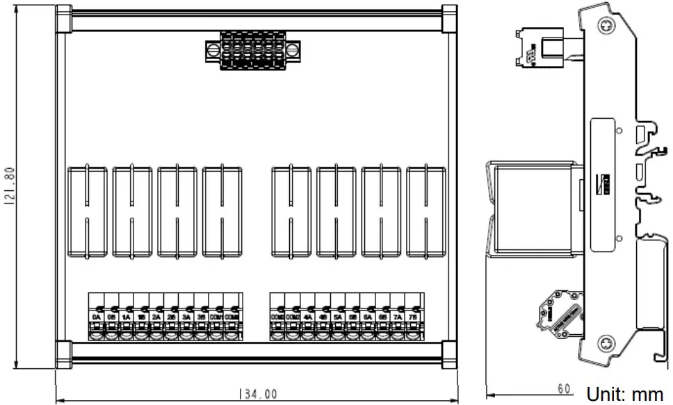
| Dimension (W*D*H) | 134 x 121 x 60.5mm |
| Weight | 358g |
| Ambient temperature (operation) | -10…+60 ˚C |
| Storage Temp. | -25 ˚C…+85 ˚C |
| Permissible Humidity(non-condensing) | RH 95%, non-condensing |
| Altitude Limit | < 2000 m |
| Ingress Protection (IP) | IP 20 |
| Pollution Severity | II |
| Safety Approval | CE |
| Wiring Range (IEC / UL) | 0.2 mm2~2.5 mm2 / AWG 24~12 |
| Wiring Ferrules | DN00508D、DN00708D、DN01008D、DN01510D |
GFAR-RM21
| Technical Specification | |
| Number of Outputs | 4 |
| Voltage Supply | 24 VDC |
| Current Consumption | <109 mA at 24 VDC” |
| Max Output Voltage | 250 VAC / 30 VDC |
| Max Output Current | 10A |
| Actuation Time | 10 ms maximum |
| Reoperate Time | 5 ms maximum |
| Communication Specification | |
| Fieldbus Protocol | Modbus RTU |
| Format | N, 8, 1 |
| Baud Rate Range | 1200-1.5 Mbps |
| General Specification | |
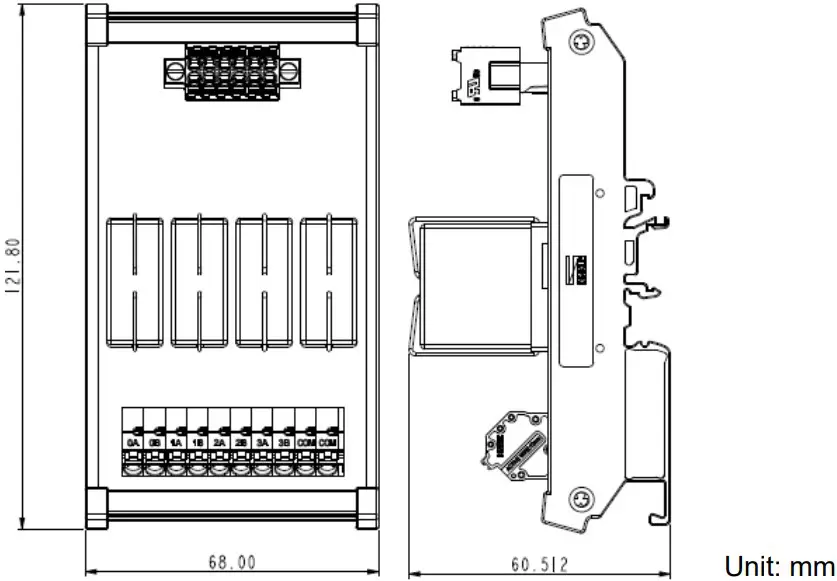
| Dimension (W*D*H) | 68 x 121.8 x 60.5mm |
| Weight | 195g |
| Ambient temperature (operation) | -10…+60 ˚C |
| Storage Temp. | -25 ˚C…+85 ˚C |
| Permissible Humidity(non-condensing) | RH 95%, non-condensing |
| Altitude Limit | < 2000 m |
| Ingress Protection (IP) | IP 20 |
| Pollution Severity | II |
| Safety Approval | CE |
| Wiring Range (IEC / UL) | 0.2 mm2~2.5 mm2 / AWG 24~12 |
| Wiring Ferrules | DN00508D、DN00708D、DN01008D、DN01510D |
Relay Output Module Information
Relay Output Module Dimension
- GFAR-RM11

- GFAR-RM21

Relay Output Module Panel Information
- GFAR-RM11

Terminal block labeling 1 2 3 4 5 7 Port definitions 24V 0V 5V 0V RS485A RS485B Terminal block B port definitions:
Terminal block labeling 0 A 0B 1 A 1B 2 A 2B Port definitions NO 1 NC 1 NO 2 NC 2 NO 3 NC 3 Terminal block labeling 3A 3B COM1 COM1 Port definitions NO 4 NC 4 Commonport Commonport Terminal block C port definitions:
Terminal block labeling COM2 COM2 4A 4B 5A 5B Port definitions Commonport Commonport NO 5 NC 5 NO 6 NC 6 Terminal block labeling 6A 6B 7A 7B Port definitions NO 7 NC 7 NO 8 NC 8 - GFAR-RM21

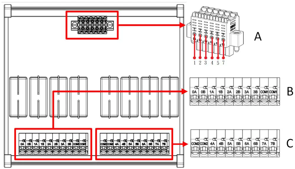
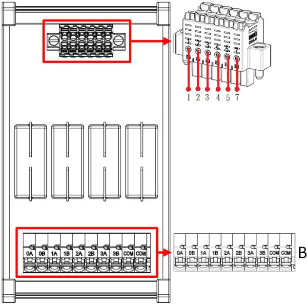
Terminal block A port definitions:
| Terminal block labeling | 1 | 2 | 3 | 4 | 5 | 7 |
| Port definitions | 24V | 0V | 5V | 0V | RS485A | RS485B |
Terminal block B port definitions:
| Terminal block labeling | 0A | 0B | 1A | 1B | 2A | 2B |
| Port definitions | NO 1 | NC 1 | NO 2 | NC 2 | NO 3 | NC 3 |
| Terminal block labeling | 3A | 3B | COM | COM | ||
| Connector definitions | NO 4 | NC 4 | Common port | Common port |
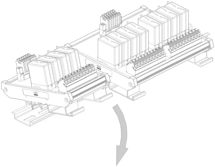
Module Installation/Disassembly
Installation
- With the front of the relay output module facing you, press the module down with the signal input ports against the upper side of the DIN rail.
- Press the module down and the plastic clamp will slide. Continue to push down until the plastic clamp “clicks”.

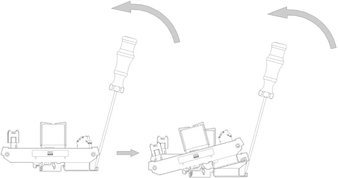
Removal
- Use a screwdriver to pull the plastic clamp sideways and detach the module from the DIN rail.
- Remove the relay output module from the DIN rail in reverse order of installation.

iO-GRID M Series Introduction
iO-GRID M series utilizes the standard Modbus communication protocol and supports Modbus RTU/ASCII and Modbus TCP. Please choose products and factory controllers to figure your system based on your communication protocol.
iO-GRID M Components
DINKLE Bus
Rail 1 to 4 are defined for power supply and rail 5 to 7 are defined for communication.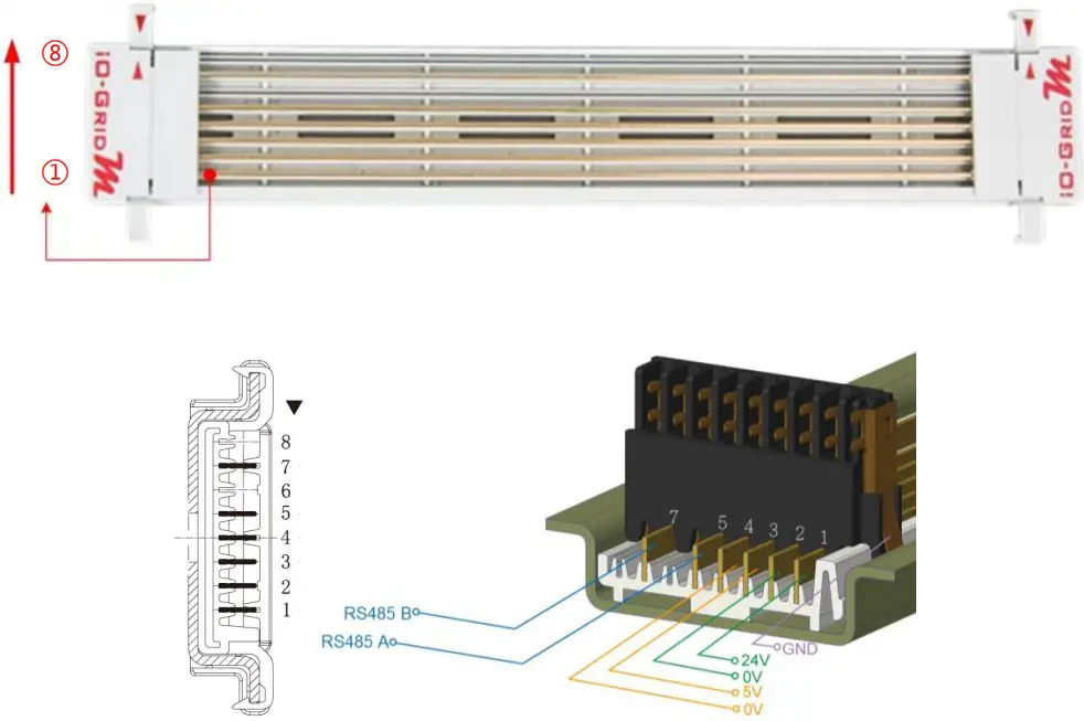
DINKLE Bus Rail Definitions:
| Rail | Definition | Rail | Definition |
| 8 | — | 4 | 0V |
| 7 | RS485B | 3 | 5V |
| 6 | — | 2 | 0V |
| 5 | RS485A | 1 | 24V |
Gateway Module
A gateway module converts between Modbus TCP and Modbus RTU/ASCII. The module provides two sets of external Ethernet ports to connect to the controller and the Internet
There are two types of gateway modules available:
4-channel gateway module: Provides 4 RS485 ports to connect to a control module Single-channel gateway module: No external connectivity for the RS485 ports.The RS485 signals are transmitted via DINKLE Bus and I/O module.
Gateway module products information:
| Product No. | Description |
| GFGW-RM01N | Modbus TCP-to-Modbus RTU/ASCII gateway module. 4 Ports |
| GFGW-RM02N | Modbus TCP-to-Modbus RTU/ASCII gateway module. 1 Port |
Control module
The control module manages I/O modules and sets up the configuration. Provides external RS485 ports to connect to the controller.
There are two types of control modules available:
3-channel control module:
Provides 3 external RS485 ports, suitable stations with 2 or more control modules. Among the RS485 ports, 2 of them will be connected to the controller and the control module of the next station.
Single-channel control module:
Provides one single RS485 port to connect to the controller, suitable for single-module stations.
Control module products information:
| Product No. | Description |
| GFMS-RM01N | RS485 control module, Modbus RTU/ASCII 3 Ports |
| GFMS-RM01S | RS485 control module, Modbus RTU/ASCII 1 Port |
I/O Module
Dinkle offers different types of I/O modules with different functions:
| Product No. | Description |
| GFDI-RM01N | 16-channel digital input module (source/sink) |
| GFDO-RM01N | 16-channel digital output module (sink) |
| GFDO-RM02N | 16-channel digital output module (Source) |
| GFAR-RM11 | 8-Channel relay module, grounded |
| GFAR-RM21 | 4-Channel relay module, grounded |
| GFAI-RM10 | 4-channel analog input module (±10VDC) |
| GFAI-RM11 | 4-channel analog input module (0…10VDC) |
| GFAI-RM20 | 4-channel analog input module (0… 20mA) |
| GFAI-RM21 | 4-channel analog input module (4… 20mA) |
| GFAO-RM10 | 4-channel analog output module (±10VDC) |
| GFAO-RM11 | 4-channel analog output module (0…10VDC) |
| GFAO-RM20 | 4-channel analog output module (0… 20mA) |
| GFAO-RM21 | 4-channel analog output module (4… 20mA) |
I/O Module Parameter Settings and Introduction
I/O Module Settings and Connections
I/O Module System Configuration List
| Name/Product No. | Description |
| GFDO-RM01N | 16-channel digital output module (sink) |
| GFDO-RM02N | 16-channel digital output module (Source) |
| GFTK-RM01 | USB-to-RS232 converter |
| Micro USB cable | Must have data transfer functionality |
| Computer | BSB-compatible |
Module Initial Setting List
| Product No. | Description | StationNo. | Baudrate | Format |
| GFMS-RM01N | RS485 control module, RTU/ASCII | 1 | 115200 | RTU(8,N,1) |
| GFDI-RM01N | 16-channel digital input module (source/sink) | 1 | 115200 | RTU(8,N,1) |
| GFDO-RM01N | 16-channel digital output module (sink) | 1 | 115200 | RTU(8,N,1) |
| GFDO-RM02N | 16-channel digital output module (Source) | 1 | 115200 | RTU(8,N,1) |
| GFAR-RM11 | 8-Channel relay module, grounded | 1 | 115200 | RTU(8,N,1) |
| GFAR-RM21 | 4-Channel relay module, grounded | 1 | 115200 | RTU(8,N,1) |
| GFAI-RM10 | 4-channel analog input module (±10VDC) | 1 | 115200 | RTU(8,N,1) |
| GFAI-RM11 | 4-channel analog input module (0…10VDC) | 1 | 115200 | RTU(8,N,1) |
| GFAI-RM20 | 4-channel analog input module (0… 20mA) | 1 | 115200 | RTU(8,N,1) |
| GFAI-RM21 | 4-channel analog input module (4… 20mA) | 1 | 115200 | RTU(8,N,1) |
| GFAO-RM10 | 4-channel analog output module (±10VDC) | 1 | 115200 | RTU(8,N,1) |
| GFAO-RM11 | 4-channel analog output module (0…10VDC) | 1 | 115200 | RTU(8,N,1) |
| GFAO-RM20 | 4-channel analog output module (0… 20mA) | 1 | 115200 | RTU(8,N,1) |
| GFAO-RM21 | 4-channel analog output module (4… 20mA) | 1 | 115200 | RTU(8,N,1) |
Setup Software Functions:
The setup software shows the I/O module station numbers, baud rates and data formats.
I/O Module Settings and Connections
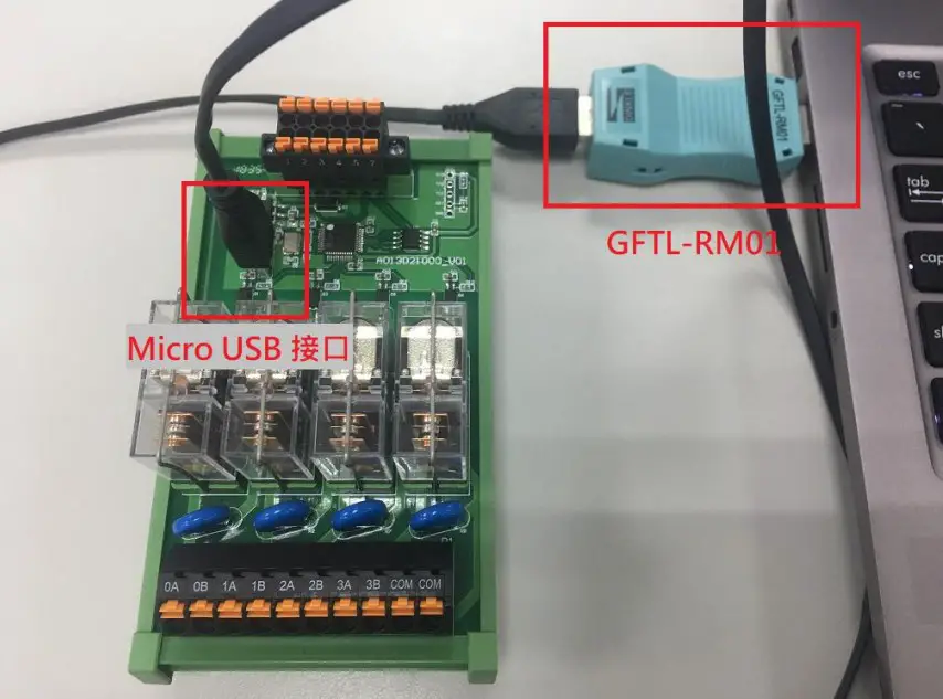
Connect the Micro USB port and GFTL-RM01 (RS232 converter) to your computer and open the iO-Grid M Utility program to set up I/O module parameter
I/O module connection illustration: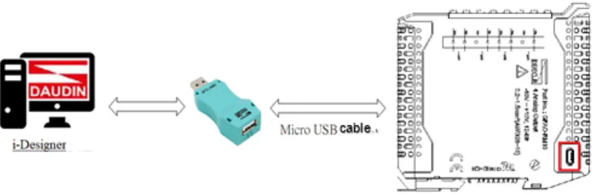
I/O module connection image: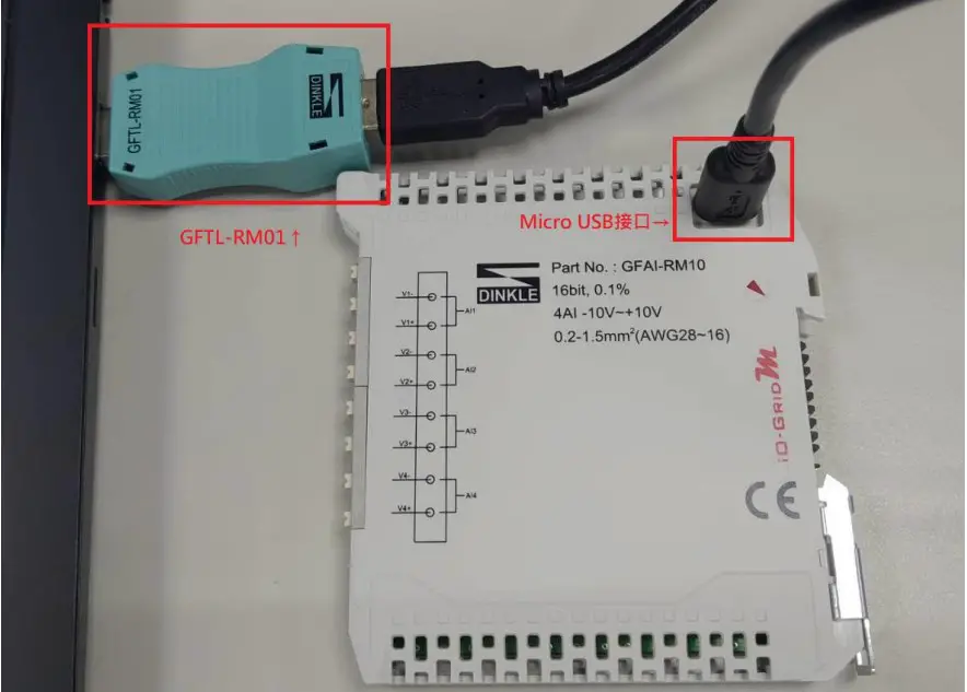
i-Designer Program Tutorial
- Connect to the I/O module using GFTL-RM01 and a Micro USB cable

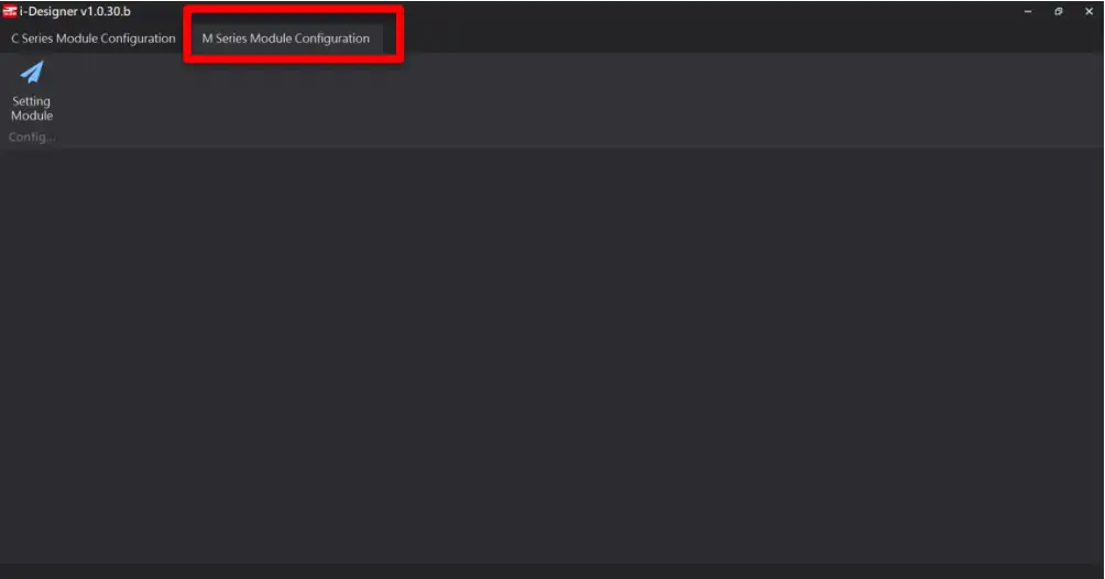
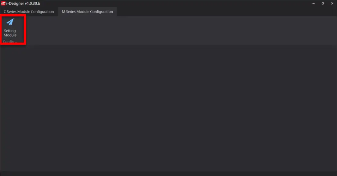
- Click to launch the software

- Select “M Series Module Configuration”

- Click on the “Setting Module” icon

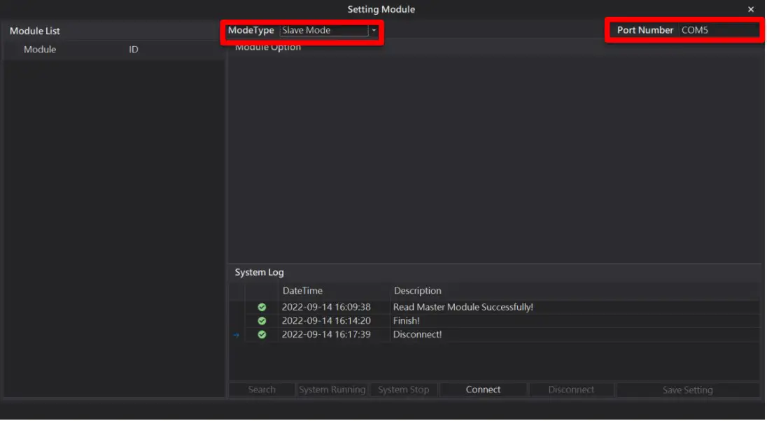
- Enter the “Setting Module” page for M-series

- Select the mode type based on the connected module

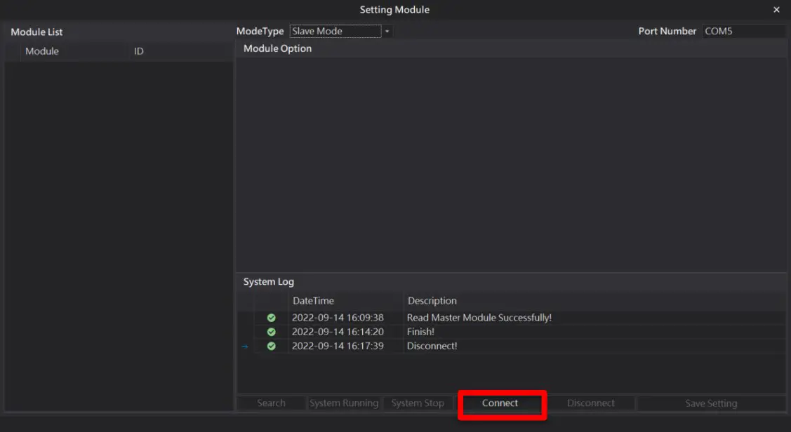
- Click on “Connect”

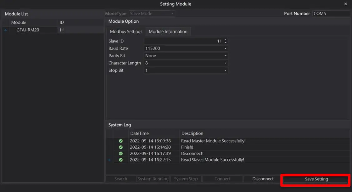
- Set up I/O modules’ station numbers and communication format (must click on “Save” after changing them)


Relay Output Module Control Register Description
Relay Output Module Register Communication Method
Use Modbus RTU/ASCII to write in single-chip relay output module registers The address for the relay output module register to be written is: 0x2000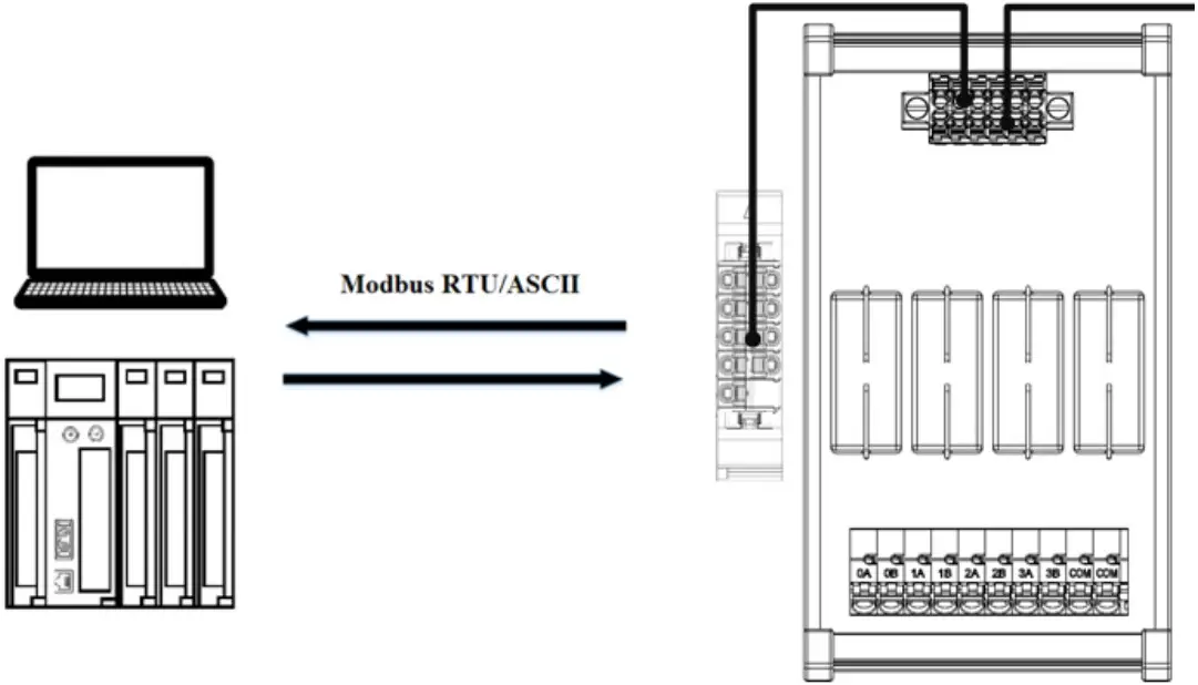
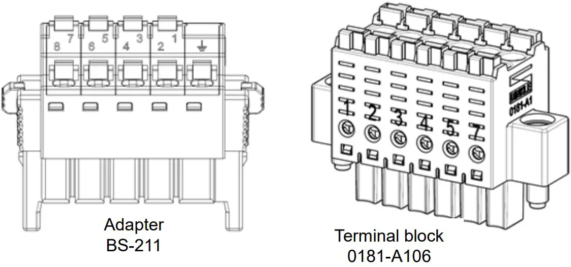
※With no control module, RS485’s physical wire must be connected with an adapter to send the signal to the power and relay output module
| 1 | 2 | 3 | 4 | 5 | 6 | 7 | 8 | |
| Adapter BS-211 | 24V | 0V | 5V | 0V | 485A | ─ | 485B | ─ |
| Terminal block 0181-A106 | 24V | 0V | 5VDC | 0V | 485A | 485B |
Use Modbus RTU/ASCII with control modules to write in relay output registers
Once a relay output module is set up with a control module, it will automatically assign the relay output
modules’ output records registers at the address of 0x2000
Example:
Two relay output module registers will be between 0x2000 and 0x2001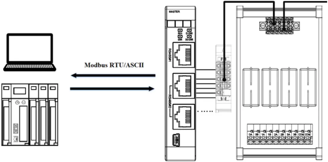
※When using control modules, RS485 can connect to control modules with BS-210 and BS-211
The configuration that uses Modbus RTU/ASCII with a control module to write in relay output modules is listed below:
| Name/Product No. | Description |
| GFMS-RM01S | Master Modbus RTU, 1 Port |
| GFAR-RM11 | 8-Channel relay module, grounded |
| GFAR-RM21 | 4-Channel relay module, grounded |
| 0170-0101 | RS485(2W)-to-RS485(RJ45 interface) |
Relay Output Module Register Format Information (0x2000, rewritable)
GFAR-RM11 Register Format: Channel open-1; channel closed – 0; reserved value – 0.
| Bit15 | Bit14 | Bit13 | Bit12 | Bit11 | Bit10 | Bit9 | Bit8 | Bit7 | Bit6 | Bit5 | Bit4 | Bit3 | Bit2 | Bit1 | Bit0 |
| Reserved | 8A | 7A | 6A | 5A | 4A | 3A | 2A | 1A | |||||||
Example: With channel 1 to 8 open:0000 0000 1111 1111 (0x00 0xFF); with all
channels closed: 0000 0000 0000 0000 (0x00 0x00).
GFAR-RM11 Register Format: Channel open-1; channel closed – 0; reserved value – 0.
| Bit15 | Bit14 | Bit13 | Bit12 | Bit11 | Bit10 | Bit9 | Bit8 | Bit7 | Bit6 | Bit5 | Bit4 | Bit3 | Bit2 | Bit1 | Bit0 |
| Reserved | 4A | 3A | 2A | 1A | |||||||||||
Example: With channel 1 to 4 open:0000 0000 0000 1111 (0x00 0x0F); with all
channels closed: 0000 0000 0000 0000 (0x00 0x00).
GFAR-RM20 Register Format: Channel open-1; channel closed – 0; reserved value – 0.
Modbus function code 0x10 Demonstration
Use Modbus RTU/ASCII to write in single-chip relay output module registers
| Modbus function code | Code sent example(ID:0x01) | Code replied example(ID:0x01) |
| 0x10 | 01 10 20 00 00 01 02 00 FF | 01 01 10 20 00 00 |
※In this example, we are writing in “0x2000” with the I/O module ID of “01” ※When not using control modules for communications, the registers will be at 0x2000
Use Modbus RTU/ASCII with control modules to write in relay output register
| Modbus function code | Code sent sample(ID:0x01) | Code replied sample(ID:0x01) |
| 0x10 | 01 10 20 00 00 01 02 00 FF | 01 01 10 20 00 00 |
※In this example, we are writing in “0x2000” with the control module ID of “01”
※When using control modules for communications, the registers will start at 0x2000


