AiM Kit Solo 2 DL for Vortex X10 ECU
Supported models
This user guide explains how to connect Vortex X10 ECU to AiM Solo 2 DL. Supported models are:
- Vortex X10
Installation note
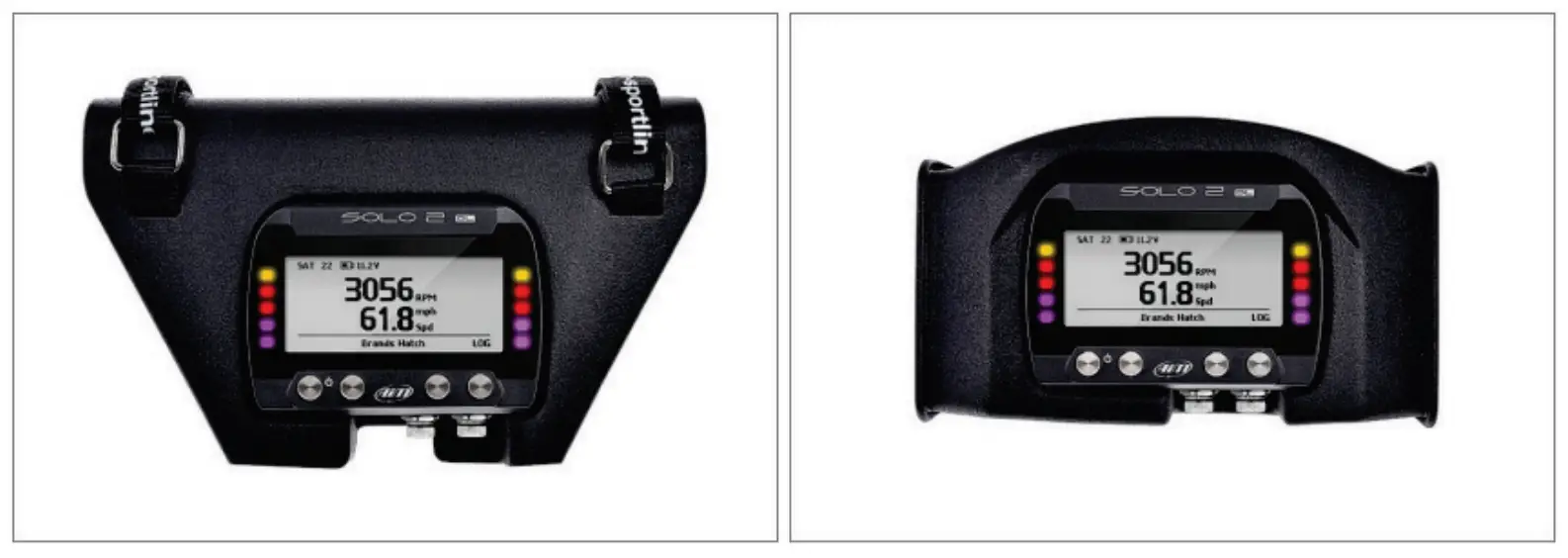
To install Solo 2 DL on your bike you can use a bar pad. AiM provides the two optional bar pads shown below:
- Bar pad for handle bar with cross brace – Part number: X47KPSOLO2T20 image on the left;
- Bar pad for handle bar without cross brace – Part number: X47KPSOLO2T10 image on the right.
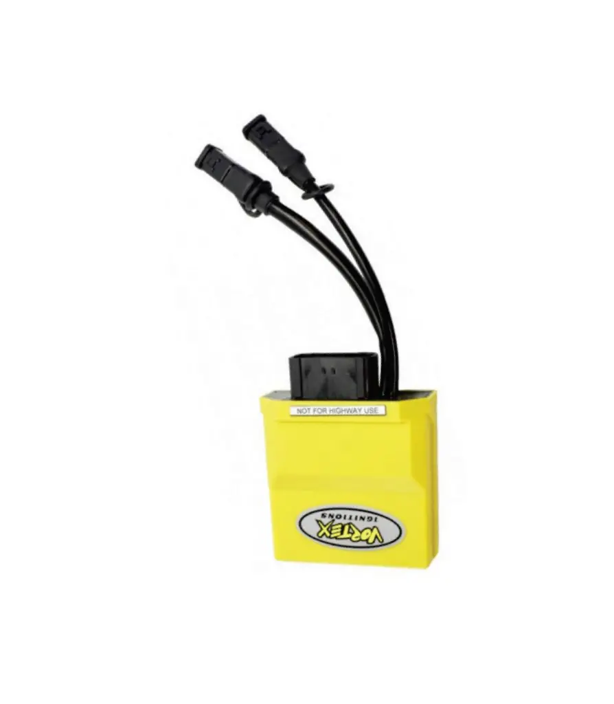
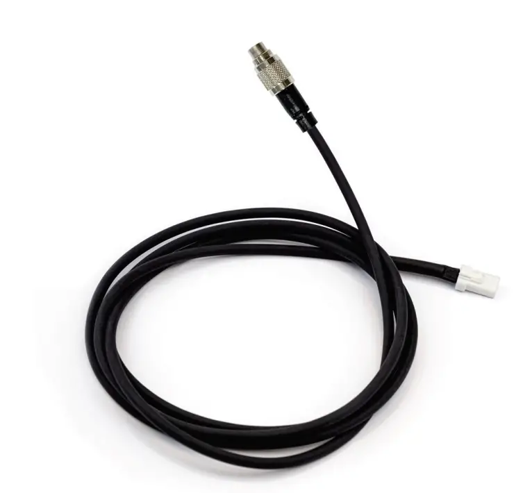
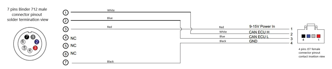
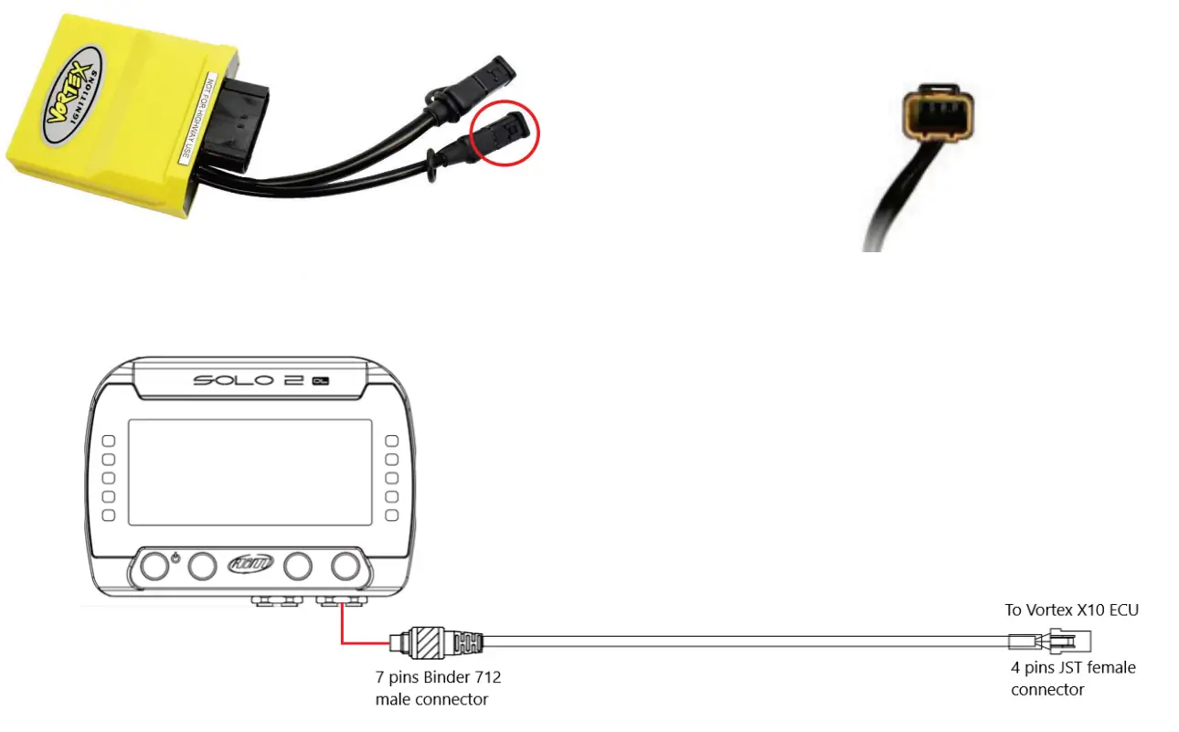
- Vortex X10 ECU can be connected to Solo 2 DL using an interface cable shown here below. Its part number is: V02589150.


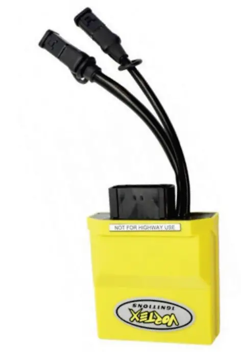
- Vortex X10 has a connector used to communicate and transmit data to an external device, the connector is highlighted below.

Race Studio 3 configuration
Before connecting the Solo 2 DL to the ECU, set all functions using AiM software Race Studio 3. The parameters to set in the device configuration are:
- ECU manufacturer: VORTEX
- ECU Model: X10 ECU
“VORTEX – X10 ECU” protocol
Channels received by Solo 2 DL configured with “VORTEX – X10 ECU” protocol are:
| CHANNEL NAME | FUNCTION |
| RPM | Engine RPM |
| TPS | Throttle position sensor |
| Ign Angle | Ignition angle |
| Inj Time | Injection time |
| Map Sel | Map selection switch |
| Low Fuel Trim SW | Low fuel trim switch |
| Mid Fuel Trim SW | Middle fuel trim switch |
| Mid Fuel Trim SW | High fuel trim switch |
| TPS Rate | Throttle position rate |
| MAP | Manifold air pressure |
| AnalogIn1 | Analog 1 |
| AnalogIn2 | Analog 2 |
| AnalogIn3 | Analog 3 |
| AnalogIn4 | Analog 4 |
| AnalogIn5 | Analog 5 |
| AnalogIn6 | Analog 6 |
| VIgn | Voltage ignition |
| BaroP | Barometric pressure |
| BaroP | Intake air pressure fuel trim |
| Ect Fuel Trim | Engine coolant temperature fuel trim |
| Baro Fuel Trim | Barometric pressure fuel trim |
| Acc Fuel Trim | Acceleration fuel trim |
| IAT | Intake air pressure |
| ECT | Engine coolant temperature |
| Fault | Fault code |
| InjDuty1 | Injection duty cycle |
| DigIn1 | Digital input 1 |
| DigIn2 | Digital input 2 |
| DigIn3 | Digital input 3 |
| DigIn4 | Digital input 4 |
| DigOut1 | Digital output 1 |
| DigOu2 | Digital output 2 |
| DigOu2 01 | Digital output 02 01 |
| DigOu4 | Digital output 04 |
| Inj End Amgle | Injection end angle |
| FirstInj Trim | First injection trim |
| Engine Kill | Engine killing |
| Flood Clear | Flood clearance |
| OutInj | Output injection |
| OutInj Dt | Output injection duty cycle |
| OutInj End Angle | Output injection end angle |
| In OutInj Split | Input/Output injection split |
| TotInj Time | Total injection time |
| Gear | Engaged gear |
| Active Map | Active MAP |
| Free Rev State | Free revolution state |
Technical note: not all data channels outlined in the ECU template are validated for each manufacturer model or variant; some of the outlined channels are model and year specific, andtherefore may not be applicable.