
![]() Operating Instructions
Operating Instructions
LCD View Finder
Model No. AK-HVF100G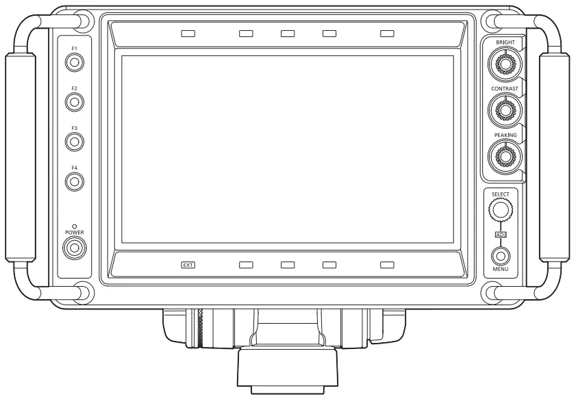
AK-HVF100G 9 Inch LCD Color Viewfinder
Before using this product, be sure to read “Read this first!” (pages 3 to 6).
Before operating this product, please read the instructions carefully and save this manual for future use.
https://pro-av.panasonic.net/manual/en/index.html
Read this first!
—— indicates safety information.
WARNING:
- To reduce the risk of fire, do not expose this equipment to rain or moisture.
- To reduce the risk of fire, keep this equipment away from all liquids. Use and store only in locations which are not exposed to the risk of dripping or splashing liquids, and do not place any liquid containers on top of the equipment.
WARNING:
Always keep accessories (camera number sheet) out of the reach of babies and small children.
CAUTION:
Do not remove panel covers by unscrewing.
No user serviceable parts inside. Refer servicing to qualified service personnel.
CAUTION:
To reduce the risk of fire and annoying interference, use the recommended accessories only.
CAUTION:
In order to maintain adequate ventilation, do not install or place this unit in a bookcase, built-in cabinet or any other confined space. To prevent risk of fire hazard due to overheating, ensure that curtains and any other materials do not obstruct the ventilation.
FCC NOTICE (USA)
This device complies with part 15 of the FCC Rules.
Operation is subject to the following two conditions:
(1) This device may not cause harmful interference, and (2) this device must accept any interference received, including interference that may cause undesired operation.
CAUTION:
This equipment has been tested and found to comply with the limits for a class A digital device, pursuant to Part 15 of the FCC Rules. These limits are designed to provide reasonable protection against harmful interference when the equipment is operated in a commercial environment. This equipment generates, uses, and can radiate radio frequency energy and, if not installed and used in accordance with the instruction manual, may cause harmful interference to radio communications. Operation of this equipment in a residential area is likely to cause harmful interference in which case the user will be required to correct the interference at his own expense.
Warning:
To assure continued FCC emission limit compliance, follow the attached installation instructions and the user must use only shielded interface cables when connecting to host computer or peripheral devices. Also, any unauthorized changes or modifications to this equipment could void the user’s authority to operate this device.
NOTIFICATION (Canada)
CAN ICES-003(A)/NMB-003(A)
IMPORTANT SAFETY INSTRUCTIONS
- Read these instructions.
- Keep these instructions.
- Heed all warnings.
- Follow all instructions.
- Do not use this apparatus near water.
- Clean only with dry cloth.
- Do not block any ventilation openings. Install in accordance with the manufacturer’s instructions.
- Do not install near any heat sources such as radiators, heat registers, stoves, or other apparatus (including amplifiers) that produce heat.
- Do not defeat the safety purpose of the polarized or grounding-type plug. A polarized plug has two blades with one wider than the other. A grounding-type plug has two blades and a third grounding prong. The wide blade or the third prong are provided for your safety. If the provided plug does not fit into your outlet, consult an electrician for replacement of the obsolete outlet.
- Protect the power cord from being walked on or pinched particularly at plugs, convenience receptacles, and the point where they exit from the apparatus.
- Only use attachments/accessories specified by the manufacturer.
 Use only with the cart, stand, tripod, bracket, or table specified by the manufacturer, or sold with the apparatus.
When a cart is used, use caution when moving the cart/apparatus combination to avoid injury from tip-over.- Unplug this apparatus during lightning storms or when unused for long periods of time.
- Refer all servicing to qualified service personnel. Servicing is required when the apparatus has been damaged in any way, such as power-supply cord or plug is damaged, liquid has been spilled or objects have fallen into the apparatus, the apparatus has been exposed to rain or moisture, does not operate normally, or has been dropped.
EMC NOTICE FOR THE PURCHASER/USER OF THE APPARATUS
- Pre-requisite conditions to achieving compliance with the above standards
<1> Peripheral equipment to be connected to the apparatus and special connecting cables
• The purchaser/user is urged to use only equipment which has been recommended by us as peripheral equipment to be connected to the apparatus.
• The purchaser/user is urged to use only the connecting cables described below.
<2> For the connecting cables, use shielded cables which suit the intended purpose of the apparatus.
• Video signal connecting cables
Use double-shielded coaxial cables, which are designed for 75-ohm type high-frequency applications, for SDI (Serial Digital Interface).
Coaxial cables, which are designed for 75-ohm type high-frequency applications, are recommended for analog video signals.
• Audio signal connecting cables
If your apparatus supports AES/EBU serial digital audio signals, use cables designed for AES/EBU.
Use shielded cables, which provide quality performance for high-frequency transmission applications, for analog audio signals.
• Other connecting cables
Use shielded cables, which provide quality performance for high-frequency applications, such as connecting cables for IEEE1394 or USB.
• When connecting to the HDMI signal terminal, use multilayer shielded cables, which provide quality performance for high-frequency applications.
• When connecting to the DVI signal terminal, use a cable with a ferrite core.
• If your apparatus is supplied with ferrite core(s), they must be attached on cable(s) following instructions in this manual. - Performance level
The performance level of the apparatus is equivalent to or better than the performance level required by these standards.
However, the apparatus may be adversely affected by interference if it is being used in an EMC environment, such as an area where strong electromagnetic fields are generated (by the presence of signal transmission towers, cellular phones, etc.). In order to minimize the adverse effects of the interference on the apparatus in cases like this, it is recommended that the following steps be taken with the apparatus being affected and with its operating environment:
1. Place the apparatus at a distance from the source of the interference.
2. Change the direction of the apparatus.
3. Change the connection method used for the apparatus.
4. Connect the apparatus to another power outlet where the power is not shared by any other appliances.
Manufactured by:
Panasonic Connect Co., Ltd.
4-1-62 Minoshima, Hakata-ku, Fukuoka 812-8531, Japan
Importer:
Panasonic Connect Europe GmbH
Authorized Representative in EU:
Panasonic Testing Centre
Winsbergring 15, 22525 Hamburg, Germany![]() Importer for UK:
Importer for UK:
Panasonic Connect UK,
a branch of Panasonic Connect Europe GmbH,
Maxis 2, Western Road, Bracknell, Berkshire, RG12 1RT![]() Disposal of Old Equipment
Disposal of Old Equipment
Only for European Union and countries with recycling systems
This symbol on the products, packaging, and/or accompanying documents means that used electrical and electronic products must not be mixed with general household waste.
For proper treatment, recovery and recycling of old products, please take them to applicable collection points in accordance with your national legislation.
By disposing of them correctly, you will help to save valuable resources and prevent any potential negative effects on human health and the environment.
For more information about collection and recycling, please contact your local municipality, dealer or supplier.
Penalties may be applicable for incorrect disposal of this waste, in accordance with national legislation.
AEEE Complies with Directive of Turkey.
Panasonic Connect Co., Ltd.
Fukuoka, Japan
Japan
Liquid crystal displays
Due to the characteristics of LCD monitors, prolonged display of bright still images or prolonged operation in high-temperature or high-humidity environments may result in residual images, luminance reduction, burn-in, banding, or panel defects and degradation that result in areas of permanently changed brightness.
In particular, avoid prolonged continuous display of the following types of images.
- Bright still images
- Images that include logomarks or graphics in fixed positions
- Windows from a computer and similar bright displays
- Images with aspect ratios different from that of the monitor (e.g., letterboxed images)
In addition, avoid prolonged continuous use in the following types of environments.
- Confined areas with high temperature and humidity
- Near the exhaust vent of air conditioning equipment, etc.
Prolonged use involving the images and environments described above will accelerate deterioration of the LCD panel over time.
To prevent accelerated deterioration and its related phenomena, we recommend the following.
- Do not display bright still images for prolonged periods.
- Lower the brightness.
- Turn off the power when the monitor is not in use.
Residual images will gradually disappear as different images are displayed.
• Various names, company names, product names, etc., described in this document are trademark or registered trademark of the respective companies.
How to read this document
- Illustrations
• The illustration may differ from actual product. - Conventions used in this manual
• The phrase within [ ] indicates the content displayed in the screen.
• Words and phrases in < > brackets indicate design text used on this camera, such as button names. - Reference pages
• Reference pages in this document are indicated by (page 00).
Before using the camera
- LCD
• The LCD monitor is manufactured with high-precision technology and has an effective pixel count of over 99.99%, but there are 0.01% of the pixels either missing or constantly lit (red, blue, green). This is normal and not a cause for concern.
• The LCD protective panel is specially treated. Wiping it or rubbing it vigorously with a hard cloth may scratch or mark its surface.
• The response rate and brightness of the LCD depend on the ambient temperature. - Handling
• Do not drop or apply excessive shock or vibration. Doing so may damage it. - Operating temperature range
• The picture quality may degrade or there may be adverse effect to internal components when used in locations as follows. Avoid using in such locations.
Cold location that is 0 °C (32 °F) or lower.
Hot location that is 45 °C (113 °F) or higher. - Maintenance
• Clean the cabinet and LCD protection panel by gently wiping them with a soft cloth.
To remove stubborn soiling, use a cloth dampened in a weak neutral detergent solution and thoroughly wrung out. Then wipe with a dry cloth.
Any moisture entering the monitor could damage it.
• Never use alcohol, thinner, or benzene to clean this unit.
Doing so may discolor the surface or cause the paint to peel.
• Do not directly expose the monitor to spray detergent. Any moisture entering the monitor could damage it. - Connecting/disconnecting the connector
• Be sure to power down the device before connecting or disconnecting the connector.
Features
This unit is an LCD viewfinder equipped with a 9.0-inch LCD panel.
This can be used as a viewfinder for the Studio Handy Camera (AK‑UC3000G/AK‑UC3000GS, AK‑HC5000G/AK‑HC5000GS, AK‑HC3800G/AK‑HC3800GS, AK‑HC3500AP/AK‑HC3500AE/AK‑HC3500AES).
Input of the external DC power supply is required when this unit is mounted to AK‑HC3800G/AK‑HC3800GS or AK‑HC3500AP/AK‑HC3500AE/AK‑HC3500AES.
The signal for video format is automatically distinguished and displays the video of the camera.
Setting for various markers, focus assist function, waveform display function, etc., can be set regardless of setting the viewfinder setting on this unit.
These functions can be assigned to the <F1>/<F2>/<F3>/<F4> buttons, and can be displayed directly by pressing the button.
Accessories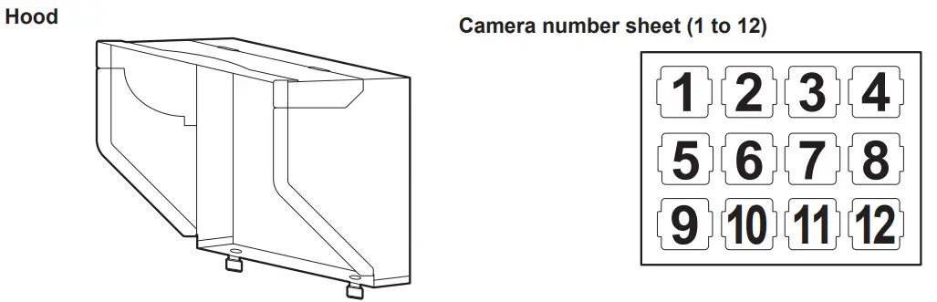 NOTE
NOTE
• After unpacking the product, dispose of the packing material properly.
Description of parts
Front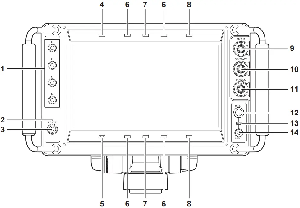
- <F1>/<F2>/<F3>/<F4> buttons
A function can be assigned to each button by [MAIN MENU] → [FUNCTION] → [FUNCTION1] to [FUNCTION4].
The function assigned to each is operated by pressing the button. For details, refer to [FUNCTION] (page 31). - <POWER> lamp
The lamp (green) is illuminated when the power is turned on.
Turns off when set to [MAIN MENU] → [SYSTEM CONFIG] → [POWER LED] → [OFF1]/[OFF2]. - <POWER> switch
This is the switch to turn on/off the power.
The power can be turned off by pressing this switch for two seconds or longer while the power is turned on. - Assignable tally lamp
This is illuminated with the condition set in [MAIN MENU] → [SYSTEM CONFIG] → [TALLY ASSIGN].
The brightness can be switched with [MAIN MENU] → [TALLY BRIGHT] → [FRONT TALLY] → [HIGH]/[MID]/[LOW]. - <EXT> lamp
This is illuminated when the lens extender is used.
The brightness can be switched with [MAIN MENU] → [TALLY BRIGHT] → [FRONT TALLY] → [HIGH]/[MID]/[LOW]. - Red tally lamp
This is illuminated when the red tally signal is input.
The brightness can be switched with [MAIN MENU] → [TALLY BRIGHT] → [FRONT TALLY] → [HIGH]/[MID]/[LOW]. - Green tally lamp
This is illuminated when the green tally signal is input.
The brightness can be switched with [MAIN MENU] → [TALLY BRIGHT] → [FRONT TALLY] → [HIGH]/[MID]/[LOW]. - Yellow tally lamp
This is illuminated when the yellow tally signal is input.
The brightness can be switched with [MAIN MENU] → [TALLY BRIGHT] → [FRONT TALLY] → [HIGH]/[MID]/[LOW]. - <BRIGHT> knob
This adjusts the brightness of the image. - <CONTRAST> knob
This adjusts the contrast of the image. - <PEAKING> knob
This adjusts the contour correction of the image. - <SELECT> dial button
This is a dial button for menu screen operation.
The cursor will move down when the <SELECT> dial button is turned clockwise. The cursor will move up when turned counterclockwise.
To select a menu item, press the <SELECT> dial button.
Sets the function to assigned with [MAIN MENU] → [FUNCTION] → [ASSIGN]. - <ADJ> lamp
The lamp (green) is illuminated during adjustment.
This is illuminated when [FUNCTION] → [ASSIGN] is set to anything other than [UNDEF]. - <MENU> button
This switches on/off of the menu.
![]() NOTE
NOTE
• The brightness for assignable tally lamp/<EXT> lamp/red tally lamp/green tally lamp/yellow tally lamp are switched simultaneously when the setting of [FRONT TALLY] is changed.
Rear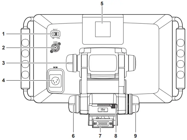
- <INPUT> switch
This switches the input (<CAM>/<SDI>).
Supported signal format for each input is as follows.
• <CAM>: 1080/59.94i, 1080/50i
• <SDI>: 1080/59.94p, 1080/50p, 1080/59.94i, 1080/50i, 720/59.94p, 720/50p- <SDI IN> terminal
This inputs the SDI signal.- Tilt friction knob
This adjusts the operation torque of tilting.
The operation torque is increased when turned more toward the <+> indicated on the knob.- <DC IN> terminal
This is the input terminal for the external DC power supply. This is connected with the external DC power supply. (DC 12 V)
The power is supplied from the I/F connector when AK‑UC3000G/AK‑UC3000GS or AK‑HC5000G/AK‑HC5000GS is connected to the unit. Input of the external DC power supply is not necessary.
The external DC power supply will be used when the external DC power supply is connected.
Input of the external DC power supply is required when this unit is mounted to AK‑HC3800G/AK‑HC3800GS or AK‑HC3500AP/AK‑HC3500AE/ AK‑HC3500AES.- Up tally lamp
This is illuminated with the control signal from the camera.
The brightness can be switched with [MAIN MENU] → [TALLY BRIGHT] → [UP TALLY] → [HIGH]/[LOW]/[OFF].
The camera number sheet (accessory) can be attached.- Lift friction knob
This adjusts the operation torque of lifting.
The operation torque is increased when turned more toward the <+> indicated on the knob.- Camera I/F connector
This is the terminal to connect to the Studio Handy Camera (AK‑UC3000G/AK‑UC3000GS, AK‑HC5000G/AK‑HC5000GS, AK‑HC3800G/ AK‑HC3800GS, AK‑HC3500AP/AK‑HC3500AE/AK‑HC3500AES).
Input of the external DC power supply is required when this unit is mounted to AK‑HC3800G/AK‑HC3800GS or AK‑HC3500AP/AK‑HC3500AE/ AK‑HC3500AES.- Pan lock lever
This will lock/unlock the panning. It is locked when the lever is moved toward <LOCK>, and unlocked by moving in other direction.- Lift lock knob
This will lock/unlock the lifting. It is locked when the knob is turned toward <LOCK>, and unlocked when turned to other direction.
Using the external DC power supply
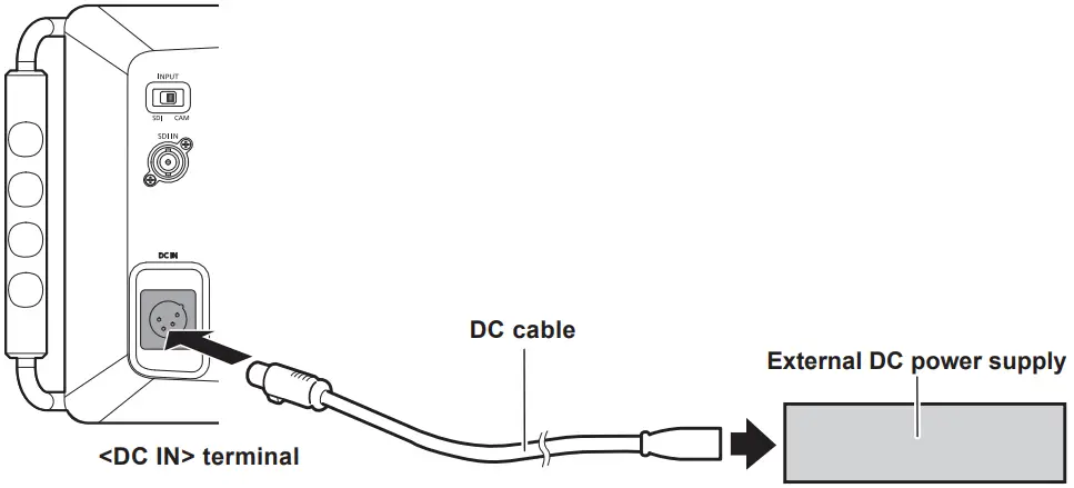
- Connect the <DC IN> terminal of the unit with the external DC power supply.
- Turn on the <POWER> switch on the external DC power supply (when there is a <POWER> switch on the external DC power supply).
- Turn on the power of the unit.
• External DC power supply
Confirm that the output voltage of the external DC power supply is compatible with the rated voltage for this unit before connecting.
Select the output current of the external DC power supply that is above the total current of the connected device with sufficient allowance.
An inrush current is generated when the power of this unit is turned on. Insufficient power supply performance while turning on the power may cause failure. It is
recommended to use the external DC power supply that can secure double or more of the total power consumption of this unit. Use 2-wire shielded cable with
cable core of AWG18 (nominal cross-section area of 0.824 mm2) or higher as the DC cable.
• Confirm the pin assignments of the DC output terminal of the external DC power supply and the <DC IN> terminal of this unit, and connect with correct polarity.
Connecting +12 V power supply to the GND terminal by mistake may cause fire or failure.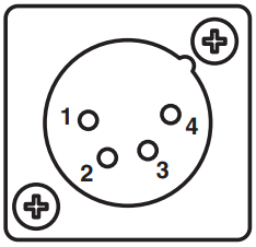
| DC IN | |
| 1 | UNREG GND |
| 2 | Not used |
| 3 | Not used |
| 4 | +12 V |
| HA16RA-4P(77) (Hirose Electric Co.) | |
Preparation
Mounting to the camera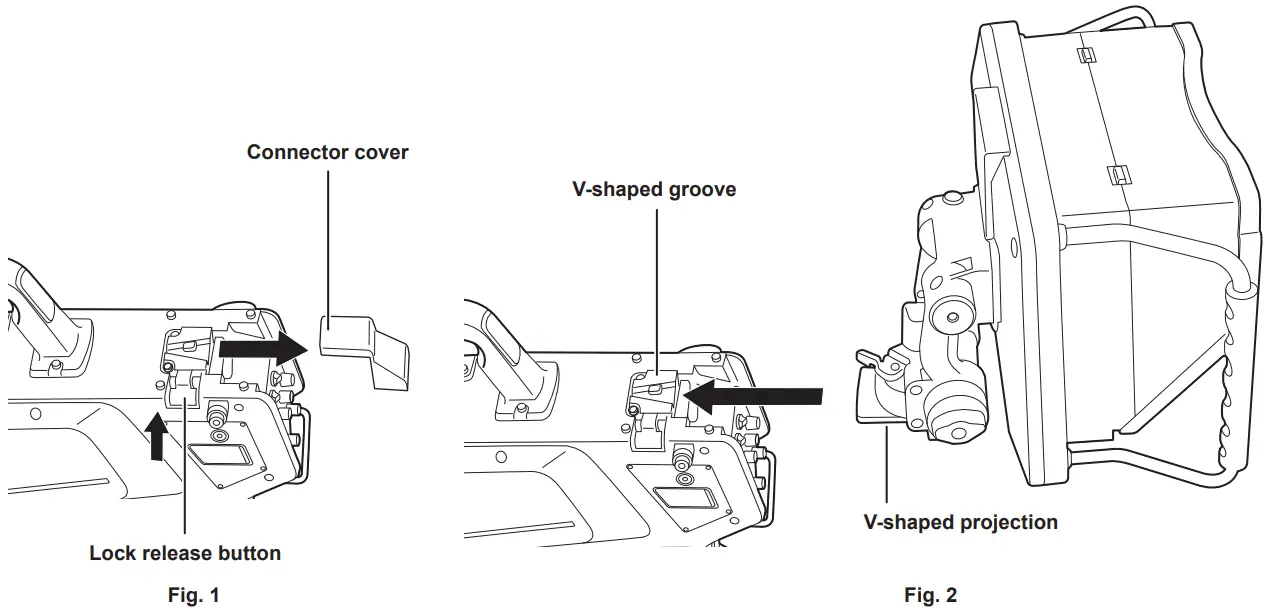
- Turn off the power of the camera and this unit.
- Press the lock release button on the camera and remove the connector cover. (Fig. 1)
- Align the V-shaped projection of this unit to the V-shaped groove on the camera, and slide and push in until it is locked. (Fig. 2)
Mounting and dismounting become easier by locking the pan lock lever and the lift friction knob on this unit.
Once the mounting is completed, confirm that this unit is securely mounted to the camera.
![]() NOTE
NOTE
- Do not hold on the hood of this unit when mounting.
- To dismount
- Turn off the power of the camera and this unit.
- Slide and dismount this unit while pressing the lock release button on the camera.
![]() NOTE
NOTE
- Do not hold on the hood of this unit when mounting.
Attaching the hood
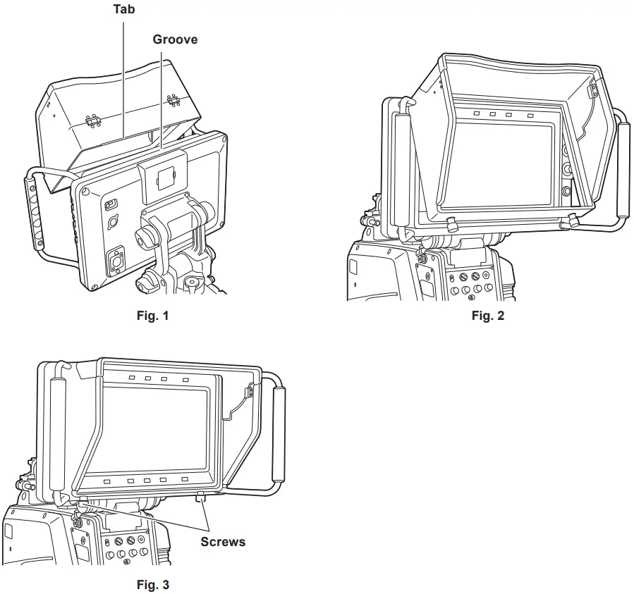
- Hook the tab on the hood to the groove at the top. (Fig. 1, Fig. 2)
- Fix with the two screws at the bottom of the hood. (Fig. 3)
To remove
- Loosen the two screws at the bottom of the hood.
- After pulling the bottom of the hood slightly forward, pull out upward.
Tilting operation
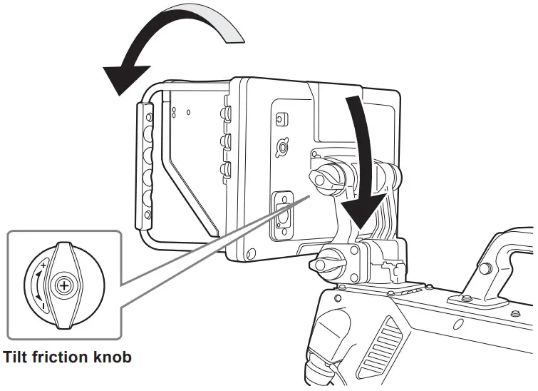
- Turn the tilt friction knob to adjust to appropriate torque.
The operation torque will become larger when turned toward <+> direction. - Adjust the tilting.
NOTE
- Do not hold onto the hood of the unit when adjusting the tilting.
Panning operation
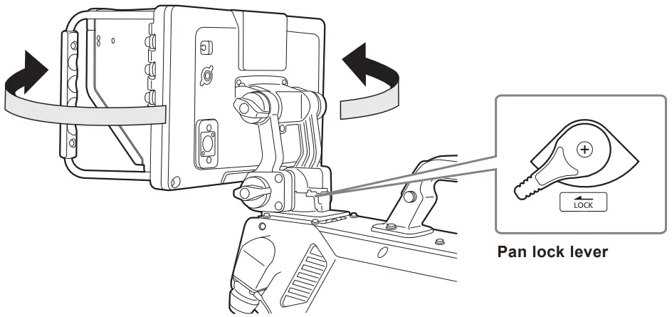
- Move the pan lock lever to the opposite direction from <LOCK>.
Panning operation is possible when moved to the opposite direction from <LOCK>. - Adjust the angle.
To fix in an arbitrary position, move the pan lock lever toward the <LOCK> direction.
NOTE
- Do not hold onto the hood of the unit when adjusting the panning.
Lifting operation
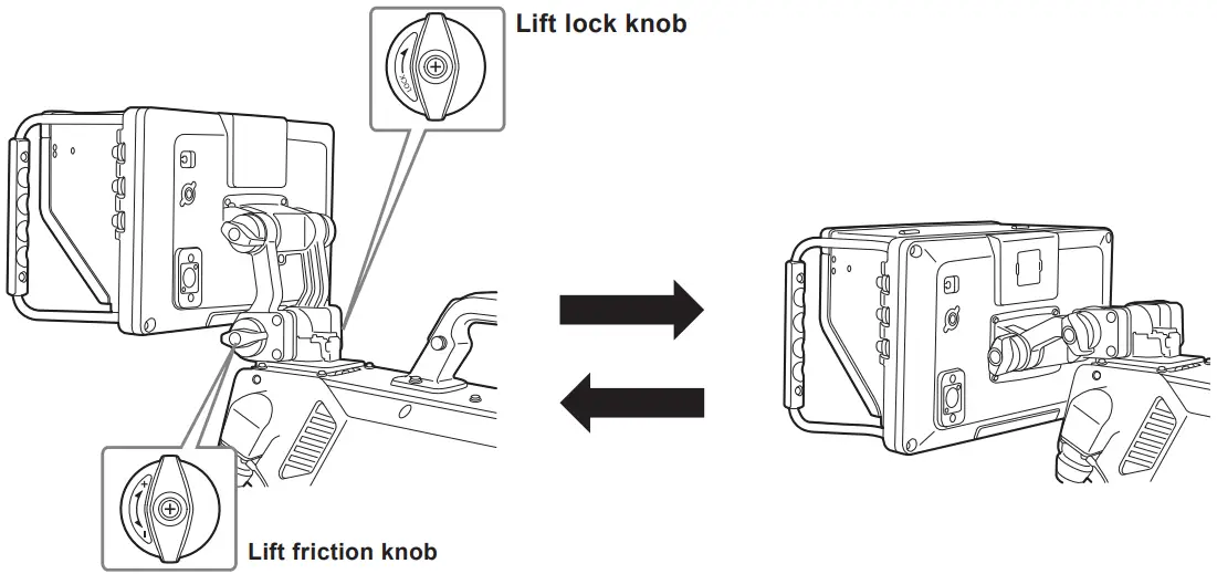
- Turn the lift lock knob to the opposite direction from <LOCK>.
Lifting operation is possible when turned to the opposite direction from <LOCK>. To fix in an arbitrary position, turn the lift lock knob toward the <LOCK> direction. - Turn the lift friction knob to adjust to appropriate torque.
The operation torque will become larger when turned toward <+> direction. - Adjust the position holding on the grip.
NOTE
- Do not hold onto the hood of the unit when adjusting the lifting.
On-screen display
Information of the operation status, function, image adjustment condition, and menu is displayed in the screen.
Operation status display
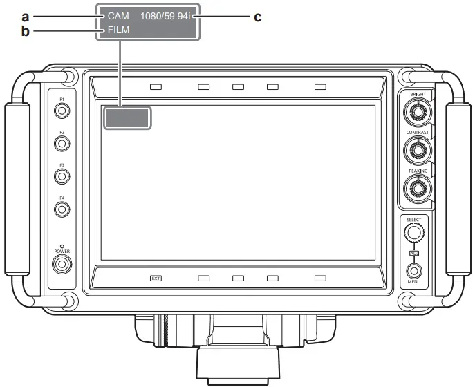
a: Input display
Displays the selected input line ([SDI] or [CAM]). (page 20)
Sets the display condition with [MAIN MENU] → [SYSTEM CONFIG] → [STATUS DISPLAY].
b: Film mode display
This is displayed when [MAIN MENU] → [VIDEO CONFIG] → [GAMMA SELECT] → [FILM] is selected.
c: Signal format display
Displays the input signal.
[UNSUPPORT SIGNAL]: A signal that is not supported is input.
[NO SIGNAL]: Signal is not input.
NOTE
- Condition of status display can be set in [MAIN MENU] → [SYSTEM CONFIG] → [STATUS DISPLAY].
The status display disappears after three seconds in the factory setting. - The displays for [UNSUPPORT SIGNAL] and [NO SIGNAL] may not display correctly.
Image adjustment knob condition display
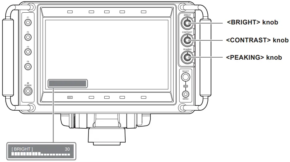
Turn the <BRIGHT>/<CONTRAST>/<PEAKING> knob.
The name and its adjustment value for the operating knob are displayed.
- This display disappears after two seconds of inaction.
- The adjustment value displayed in green is factory setting.
Function display
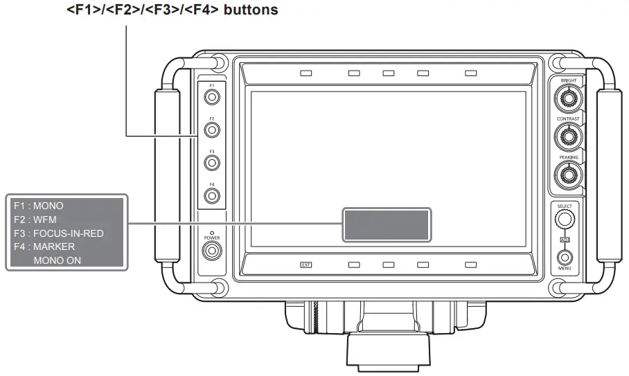
Press the <F1>/<F2>/<F3>/<F4> button.
Function assigned to each button and the condition of that function is displayed.
- This display disappears after two seconds of inaction.
- Display condition can be changed with [MAIN MENU] → [FUNCTION] → [FUNCTION DISPLAY].
- The function assigned to each button will memorize the condition before turning off the power even if the power of the unit is turned off. However, [FOCUS‑IN‑RED] and [CAM MENU] will return to disabled.
Mode check display
Current setting condition can be displayed.
Perform while the menu is not displayed.
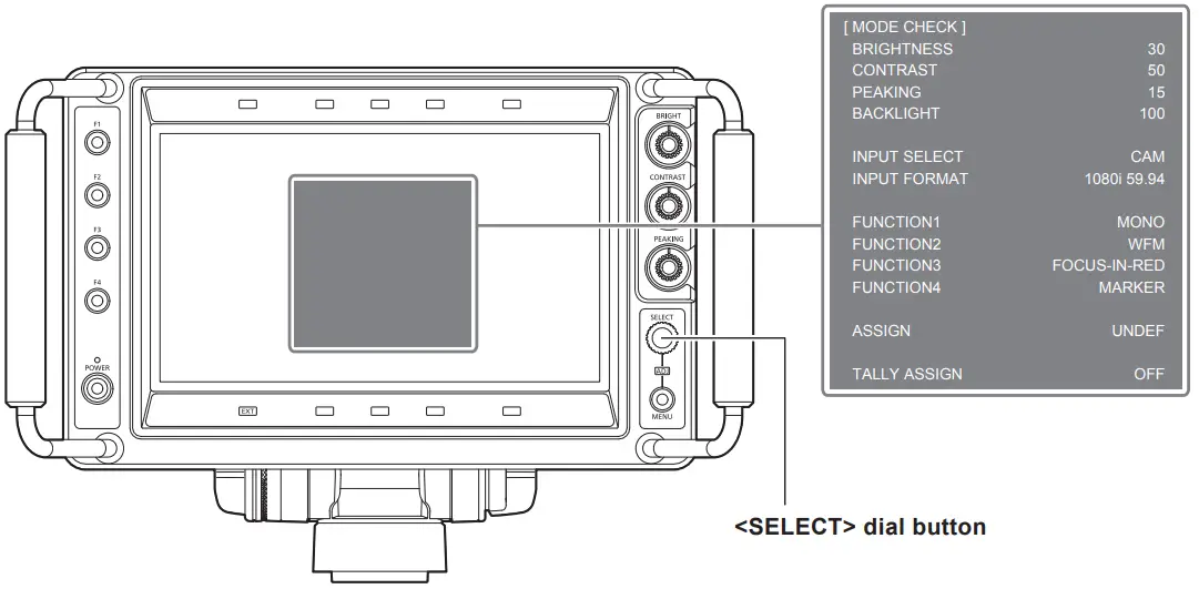
Press the <SELECT> dial button.
The setting condition is displayed.
Display disappears when there is approximately two minutes of inaction.
- [BRIGHTNESS]: The value adjusted with the <BRIGHT> knob.
- [CONTRAST]: The value adjusted with the <CONTRAST> knob.
- [PEAKING]: The value adjusted with the <PEAKING> knob.
- [BACK LIGHT]: The value set with [MAIN MENU] → [VIDEO CONFIG] → [BACK LIGHT].
- [INPUT SELECT]: Input selected with the <INPUT> switch.
- [INPUT FORMAT]: Format of the video signal currently input.
- [FUNCTION1]: Function assigned to the <F1> button.
- [FUNCTION2]: Function assigned to the <F2> button.
- [FUNCTION3]: Function assigned to the <F3> button.
- [FUNCTION4]: Function assigned to the <F4> button.
- [ASSIGN]: Function assigned to the <SELECT> dial button.
- [TALLY ASSIGN]: The illumination condition set with [MAIN MENU] → [SYSTEM CONFIG] → [TALLY ASSIGN].
The menu of the camera (only AK‑UC3000G/AK‑UC3000GS and AK‑HC5000G/AK‑HC5000GS) can be operated from this unit.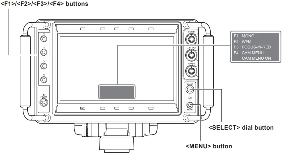
- Set [CAM MENU] to one of the <F1>/<F2>/<F3>/<F4> buttons with [MAIN MENU] → [FUNCTION] → [FUNCTION1]/[FUNCTION2]/ [FUNCTION3]/[FUNCTION4].
- Press one of the <F1>/<F2>/<F3>/<F4> buttons that [CAM MENU] is set.
- Press the <MENU> button.
The menu screen of the camera is displayed. - Turn the <SELECT> dial button and select the item.
- Press the <SELECT> dial button.
For the operating method of the menu, refer to the Operating Instruction of the camera.
NOTE
- The setting for [CAM MENU] is cleared when the power is turned off.
Menu operations
The menu operation method, structure of the setting menu, and details of the setting menu are described.
Basic operations
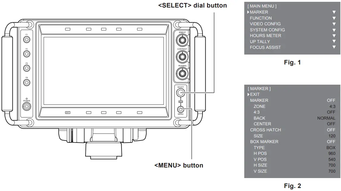
- Press the <MENU> button.
[MAIN MENU] is displayed. (Fig. 1)
Previous menu is displayed by pressing the <MENU> button when [MAIN MENU] → [SYSTEM CONFIG] → [MENU RESUME] → [ON] is set.
[MAIN MENU] is displayed when the power is turned off once and then turned on again. - Turn the <SELECT> dial button and select the menu item.
- Press the <SELECT> dial button.
The selected item is opened. (Fig. 2) - Turn the <SELECT> dial button and select the item to set.
- Press the <SELECT> dial button.
The setting value changes to green. - Turn the <SELECT> dial button and change the setting.
To cancel, press the <MENU> button. - Press the <SELECT> dial button.
The setting is confirmed.
![]() NOTE
NOTE
- This display disappears after two minutes of inaction. The value displayed at that time will be confirmed as the setting value when the display disappears.
[ASSIGN] setting ([ASSIGN] condition display)
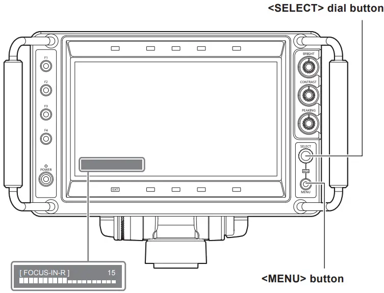
- Select the function to be assigned to the <SELECT> dial button with [MAIN MENU] → [FUNCTION] → [ASSIGN].
- Press the <SELECT> dial button.
- Press the <MENU> button to close the menu.
- Turn the <SELECT> dial button to change the setting.
The function that is being operated and its adjustment value are displayed.
This display disappears after two seconds of inaction.
Key lock setting
Operation of the <F1>/<F2>/<F3>/<F4> button, <SELECT> dial button, and <MENU> button can be disabled.
The <POWER> button, <BRIGHT> knob, <CONTRAST> knob, and <PEAKING> knob cannot be disabled.
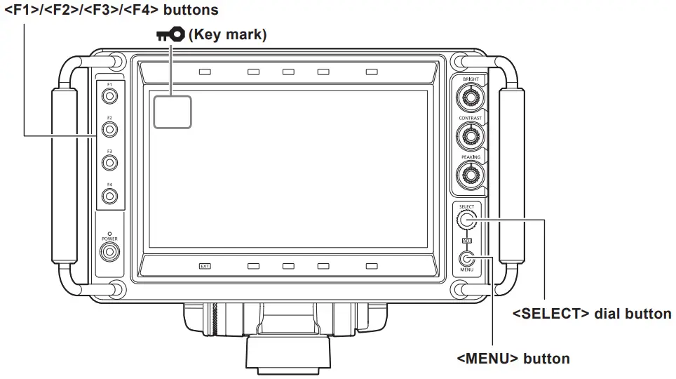
- Press the <SELECT> dial button while operating to display the mode check display, and then press and hold the <MENU> button for three seconds or longer.
A key mark is constantly displayed at the top left of the screen while in key lock.
• The setting is cleared when the power is turned off.
• To clear the key lock, press and hold the <MENU> button for three seconds or longer.
| [MARKER] | Performs the setting regarding the marker. |
| [FUNCTION] | Performs the setting regarding the operation of the <F1>I<F2>1<F3>b<F4> buttons. |
| [VIDEO CONFIG] | Performs the setting regarding the screen. |
| [SYSTEM CONFIG] | Performs the setting regarding the system. |
| [HOUR METER] | Displays the elapsed time and illuminated time of the backlight. |
| [TALLY BRIGHT] | Sets the brightness of the up tally lamp and front tally lamp. |
Item | Setting content | |
| [EXIT] | Returns to the upper level. | |
| [MARKER] | — | Sets if the marker is displayed in the screen or not. [ON], [OFF] Factory setting: [OFF] [BOX MARKER] is set to [OFF] when [BOX MARKER] is [ON1]/[ON2] and [MARKER] is set to [ON]. |
| [ZONE] | Selects the type of marker. [OFF]: Marker is not displayed. [4:3]: Marker of 4:3 size. [13:9]: Marker of 13:9 size. [14:9]: Marker of 14:9 size. [CNSCO2.39]: Marker of 2.39:1 size. [CNSCO2.35]: Marker of 2.35:1 size. [2:1]: Marker of 2:1 size. [VISTA]: Marker of 1.85:1 size. [95%]: Marker of 95% area. [93%]: Marker of 93% area. [90%]: Marker of 90% area. [88%]: Marker of 88% area. [80%]: Marker of 80% area. [USER85%]: Variable area marker between the range of 80% to 100% (in 1% steps) (can be set by pressing the <SELECT> dial button and the setting value changes to light blue) (factory setting is [85%]) f Factory setting: [4:3] | |
| [4:3] | Selects the type of marker displayed when the image aspect ratio is 4:3. [OFF]: Marker is not displayed. [95%]: Marker of 95% area. [93%]: Marker of 93% area. [90%]: Marker of 90% area. [88%]: Marker of 88% area. [80%]: Marker of 80% area. [USER85%]: Variable area marker between the range of 80% to 100% (in 1% steps) (can be set by pressing the <SELECT> dial button and the setting value changes to light blue) (factory setting is [85%]) f Factory setting: [OFF] | |
| [BACK] | Sets the background brightness outside the marker set with [ZONE]. [NORMAL]: Normal background. [HALF]: Background brightness is set to 50%. [BLACK]: Background brightness is set to 0% (black). f Factory setting: [NORMAL] | |
| [CENTER] | Sets if the center marker is displayed or not. [ON], [OFF] f Factory setting: [OFF] | |
| [CROSS HATCH] | — | Sets the display and density of the cross hatch. [OFF]: Does not display. [LOW]: Dim cross hatch is displayed. [HIGH]: Bright cross hatch is displayed. f Factory setting: [OFF] |
| [SIZE] | Selects the cross hatch size. [60]: 60 dots and 60 lines [120]: 120 dots and 120 lines Factory setting: [120] | |
| [BOX MARKER] | — | Sets if the box marker is displayed in the screen or not. Two patterns of [ON1] and [ON2] can be recorded. [ON1], [ON2], [OFF] Factory setting: [OFF] [MARKER] is set to [OFF] when [MARKER] is [ON] and [BOX MARKER] is set to [ON1]/[ON2]. |
| [TYPE] | Sets the display type of the box marker. [BOX]: Box type display. [CROSS]: Cross type display. f Factory setting: [BOX] | |
| [H POS] | Sets the horizontal position to display the box marker. [10]…[1910] (in 10 dots step) Factory setting: [960] | |
| [V POS] | Sets the vertical position to display the box marker. [10]…[1070] (in 10 lines step) Factory setting: [540] | |
| [H SIZE] | Sets the horizontal size of the box marker. [10]…[1910] (in 10 dots step) Factory setting: [700] | |
| [V SIZE] | Sets the vertical size of the box marker. [10]…[1070] (in 10 lines step) Factory setting: [700] | |
FUNCTION
Item | Setting content |
| [EXIT] | Returns to the upper level. |
| [FUNCTION1] | Selects the function assigned to the <F1> button. [SCAN]: Switches between the underscan and normal display. [WFM]: Displays the waveform display screen. [MARKER]: Displays the marker. [FOCUS-IN-RED]: Switches the enable/disable of the function to enhance the focused part of the image (disabled when [WFM] is displayed, disabled when there is no input signal, setting is cleared when the power is turned off, and the detection sensitivity can be changed with the <SELECT> dial button during the operation when [FOCUS-IN-RED] is assigned with [MAIN MENU] ® [FUNCTION] ® [ASSIGN]). [CROSS HATCH]: Switches the cross hatch display. [MONO]: Switches between the color and monochrome display. [UP TALLY]: Switches the on/off of the up tally lamp. [FRONT TALLY]: Switches the brightness of the front tally lamp. [CAM MENU]: Switches the enable/disable of the camera menu operation function (setting is canceled when the power is turned off). [FOCUS ASSIST]: Switches the enable/disable of the focus assist function on the camera. [ZOOM LINK]: Switches the enable/disable of the detail function on the viewfinder linked with the zoom. [UNDEF]: Function is not assigned. f Factory setting: [MONO] [CAM MENU], [FOCUS ASSIST], and [ZOOM LINK] can be operated only when the camera (AK-UC3000G/AK-UC3000GS, AK-HC5000G/AK-HC5000GS) is connected. |
| [FUNCTION2] | Selects the function assigned to the <F2> button. [SCAN]: Switches between the underscan and normal display. [WFM]: Displays the waveform display screen. [MARKER]: Displays the marker. [FOCUS-IN-RED]: Switches the enable/disable of the function to enhance the focused part of the image (disabled when [WFM] is displayed, disabled when there is no input signal, setting is cleared when the power is turned off, and the detection sensitivity can be changed with the <SELECT> dial button during the operation when [FOCUS-IN-RED] is assigned with [MAIN MENU] ® [FUNCTION] ® [ASSIGN]). [CROSS HATCH]: Switches the cross hatch display. [MONO]: Switches between the color and monochrome display. [UP TALLY]: Switches the on/off of the up tally lamp. [FRONT TALLY]: Switches the brightness of the front tally lamp. [CAM MENU]: Switches the enable/disable of the camera menu operation function (setting is canceled when the power is turned off). [FOCUS ASSIST]: Switches the enable/disable of the focus assist function on the camera. [ZOOM LINK]: Switches the enable/disable of the detail function on the viewfinder linked with the zoom. [UNDEF]: Function is not assigned. Factory setting: [WFM] [CAM MENU], [FOCUS ASSIST], and [ZOOM LINK] can be operated only when the camera (AK-UC3000G/AK-UC3000GS, AK-HC5000G/AK-HC5000GS) is connected. |
| [FUNCTION3] | Selects the function assigned to the <F3> button. [SCAN]: Switches between the underscan and normal display. [WFM]: Displays the waveform display screen. [MARKER]: Displays the marker. [FOCUS-IN-RED]: Switches the enable/disable of the function to enhance the focused part of the image (disabled when [WFM] is displayed, disabled when there is no input signal, setting is cleared when the power is turned off, and the detection sensitivity can be changed with the <SELECT> dial button during the operation when [FOCUS-IN-RED] is assigned with [MAIN MENU] ® [FUNCTION] ® [ASSIGN]). [CROSS HATCH]: Switches the cross hatch display. [MONO]: Switches between the color and monochrome display. [UP TALLY]: Switches the on/off of the up tally lamp. [FRONT TALLY]: Switches the brightness of the front tally lamp. [CAM MENU]: Switches the enable/disable of the camera menu operation function (setting is canceled when the power is turned off). [FOCUS ASSIST]: Switches the enable/disable of the focus assist function on the camera. [ZOOM LINK]: Switches the enable/disable of the detail function on the viewfinder linked with the zoom. [UNDEF]: Function is not assigned. f Factory setting: [FOCUS-IN-RED] [CAM MENU], [FOCUS ASSIST], and [ZOOM LINK] can be operated only when the camera (AK-UC3000G/AK-UC3000GS, AK-HC5000G/AK-HC5000GS) is connected. |
[VIDEO CONFIG]
Item | Setting content | |
| [EXIT] | Returns to the upper level. | |
| [GAMMA SELECT] | — | Selects the gamma curve. [STANDARD]: Standard mode. [FILM]: Film mode (displays [FILM] at the top left of the screen). Factory setting: [STANDARD] |
| [FILM GAMMA] | Selects the type of the film gamma mode in accordance with the gamma setting on the camera. [FILM REC]: When [FILM REC] is selected. [OTHER]: When anything other than [FILM REC] is selected. Conceptual diagram of gamma curve 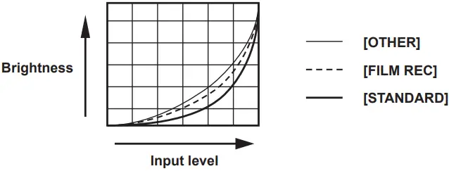 Factory setting: [FILM REC] | |
| [COLOR TEMP.] | Selects the color temperature. [USER 0]…[USER 63]: Variable settings 0 to 63 (equivalent to color temperature of 3000 K to 9300 K) (can be set when the <SELECT> dial button is pressed and the setting value changes to light blue). [D93]: Equivalent to color temperature of 9300 K [D65]: Equivalent to color temperature of 6500 K [D56]: Equivalent to color temperature of 5600 K Factory setting: [D65] | |
[FOCUS ASSIST
Item | Setting content | |
| [EXIT] | Returns to the upper level. | |
| [FOCUS-IN-RED] | — | Sets the enable/disable of the function to enhance the part that is focused in the image on this unit. Disabled while [WFM] is displayed. Disabled when there is no input signal. (setting is canceled when the power is turned off) [OFF], [ON] Factory setting: [OFF] |
| [IN-RED-COLOR] | Sets the display color of the function to enhance the part that is focused in the image on this unit. [RED], [GREEN], [BLUE], [WHITE] Factory setting: [RED] | |
| [ZOOM LINK] | — | Sets the enable/disable of the detail function on the viewfinder linked with the zoom. [OFF], [ON] Factory setting: [OFF] This item can be operated only when the camera (AK-UC3000G/AK-UC3000GS, AK-HC5000G/ AK-HC5000GS) is connected. |
| [LINK LEVEL] | Sets the detail level of the viewfinder linked with the zoom. [LOW], [MID], [HIGH] Factory setting: [LOW] | |
| [FOCUS ASSIST] | Sets the enable/disable of the focus assist function on the camera. [OFF], [ON] Factory setting: [OFF] This item can be operated only when the camera (AK-UC3000G/AK-UC3000GS, AK-HC5000G/ AK-HC5000GS) is connected. | |
Maintenance and Inspection
Maintenance and inspection are performed with periodic and appropriate maintenance to maintain the function of the unit in constantly good condition so the customers can use the unit safely.
Make sure to execute the maintenance and inspection for the function of the unit to last long in good condition.
Periodic maintenance service
The LCD panel is equipped with a backlight. The backlight is a consumable component that deteriorates and eventually breaks down.
Therefore, it is important to perform a periodic maintenance service on top of the conventional service performed at the time of failure. The performance of the device is maintained in good condition, and unexpected failure due to consumable parts can be avoided by the maintenance service.
Specification
Dimensions
General
Power
DC![]() 12 V (supplied from camera or XLR)
12 V (supplied from camera or XLR)
Power consumption
18 W
indicates safety information.
| Ambient operating temperature | 0 °C – 45 °C (32 °F – 113 °F) |
| Storage temperature | -20 °C – 60 °C (-4 °F – 140 °F) |
| Ambient operating humidity | 10% – 85% (no condensation) |
| Weight | Approx. 2.6 kg (5.73 lbs.) (not including hood) Approx. 3.0 kg (6.61 lbs.) (including hood) |
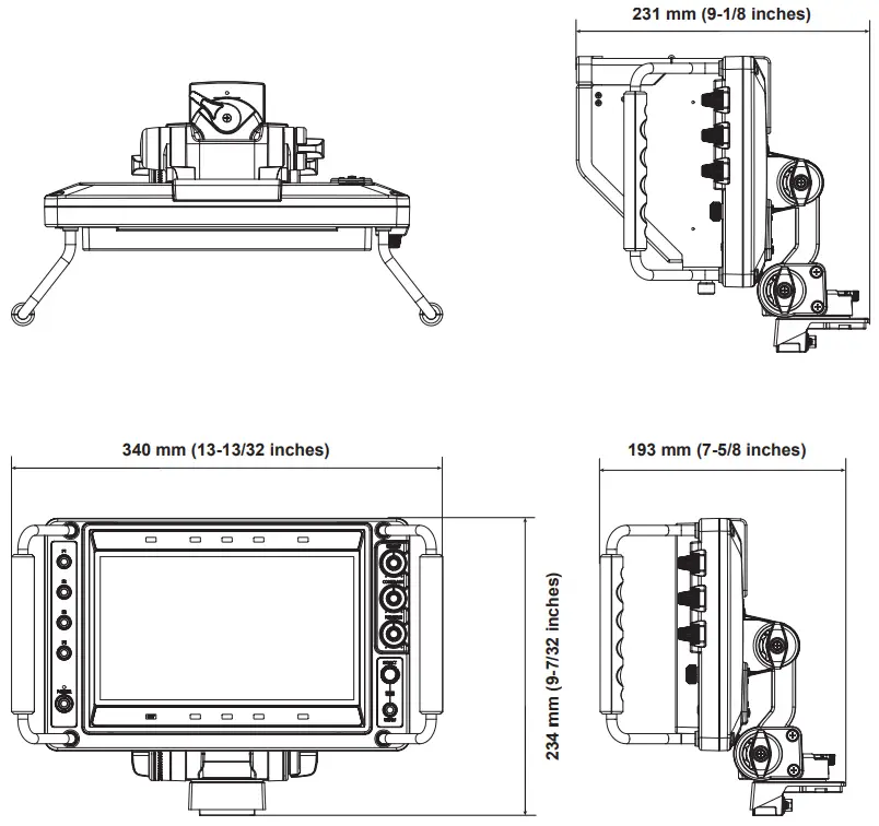
| Dimensions (WxHxD) | 340 mmx234 mmx193 mm (13-13/32 inchesx9-7/32 inchesx7-5/8 inches) (not including hood) 340 mmx234 mmx231 mm (13-13/32 inchesx9-7/32 inchesx9-118 inches) (including hood) |
Display panel
| Dimensions | 9.0 inches |
| Number of pixels | 1920×1080 (FHD) |
| Display color | Approx. 16.77 million colors |
Switch function/connector
| Operation | <POWER> switch <MENU> button <SELECT> dial button <F1>/<F2>/<F3>/<F4> buttons <BRIGHT> knob <CONTRAST> knob <PEAKING> knob <INPUT> switch |
| Connector | Camera I/F connector (D‑sub 29 pins × 1) SDI IN connector (BNC × 1) DC IN connector (XLR 4 pins × 1) |
Supported signal format
| CAM | 1080/59.94i, 1080/50i |
| SDI | 1080/59.94p, 1080/50p, 1080/59.94i, 1080/50i 720/59.94p, 720/50p |
Connector pin assignment table
Camera I/F connector (D‑sub 29 pins)
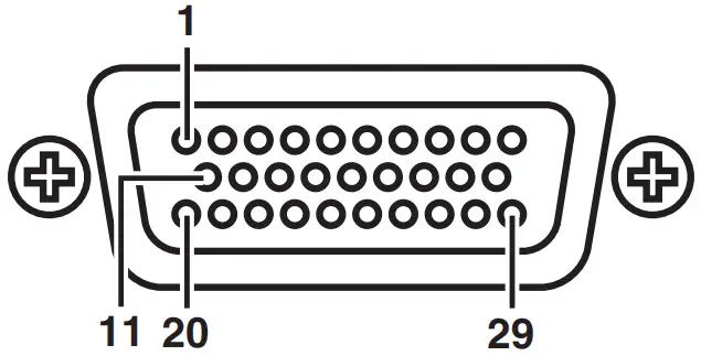
| 1 | Y | 11 | Y GND | 21 | Not used |
| 2 | Pa | 12 | Ps GND | 22 | Not used |
| 3 | PR | 13 | PR GND | 23 | Not used |
| 4 | CAM DET | 14 | Not used | 24 | l2C CLK |
| 5 | l2C DATA | 15 | DGND | 25 | G TALLY |
| 6 | R TALLY | 16 | Not used | 26 | P REQ |
| 7 | UP TALLY | 17 | UNREG-GND | 27 | Not used |
| 8 | VF12 V | 18 | Not used | 28 | Not used |
| 9 | VF12 V | 19 | FGND | 29 | Not used |
| 10 | VF12 V | 20 | (LCD ACT) |
D02-29PF-N-F0 (Japan Aviation Electronics Industry)


