![]()
SIM-03
DIGITAL QUAD PIR AND
MICROWAVE/ANTIMASKING
DETECTOR
INSTALLATION INSTRUCTIONS
P/N 7106777 Rev A
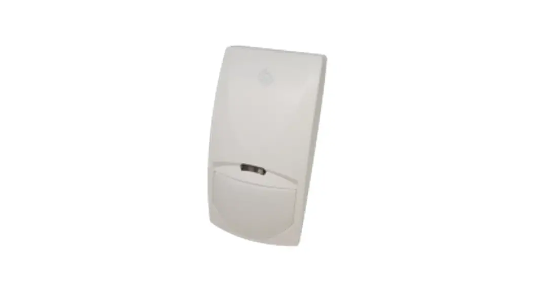
SIM-03 Digital Quad Pir and Microwave Antimasking Detector
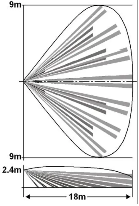
Wide Angle Lens
AVOID THE FOLLOWING LOCATIONS:
- Facing direct sunlight.
- Facing areas that may change temperature rapidly.
- Areas where there are air ducts or substantial airflows.
- Avoid screens, and curtains that may block the detection area.
- Do not install outdoors.
SPECIFICATION
| Detection Method Power Input Current Draw Temperature Compensation Alarm Period Alarm Output with protection Tamper Switch with protectionWarm Up Period LED Indicator | PIR element & microwave pulse Doppler 8.2 to 16 Vdc Active : 25.5 mA Standby: 16.5 mA YES 2 +/- 1 sec N.C 28Vdc 0.1 A 10 Ohm series resistors N.C 28Vdc 0.1A 10 Ohm series resistor – open when cover is removed 1 min Yellow during warm-up and self-testing Red during alarm Green: PIR CHANNEL Yellow: MW CHANNEL |
INSTALLING THE DETECTOR
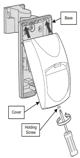 | 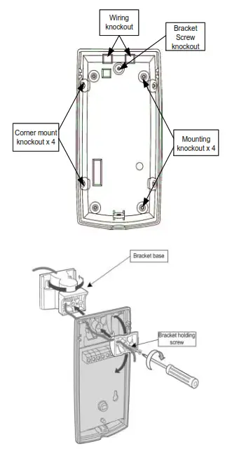 |
WIRE REQUIREMENTS
Use #22 AWG (0.5mm) or wires with a larger diameter. Use the following table to determine the required wire gauge (diameter) and length of wire between the detector and the control panel.
| (Wire Length | m | 200 | 300 | 400 | 800 |
| Wire Diameter | mm | .75 | 1.0 | 1.5 | |
| Wire Length | ft | 800 | 1200 | 2000 | 3400 |
| Wire Gauge | # | 22 | 20 | 18 | 16 |
PCB LAYOUT
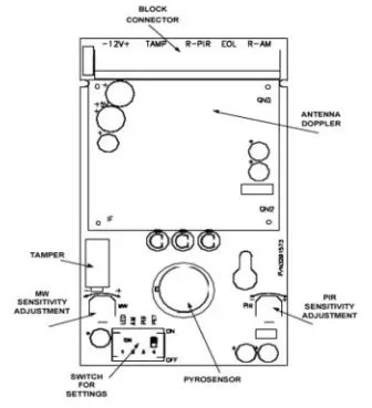
WIRE CONNECTIONS
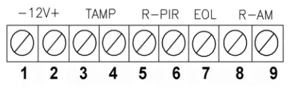
Terminal 1 – Marked “ – ” (GND)
Connect to the negative Voltage or ground of the control panel.
Terminal 2 – Marked “ + ” (+12V)
Connect to a positive Voltage of 8.2 -16Vdc source.
Terminals 3 & 4 – Marked “ TAMP ”
If a Tamper function is required connect these terminals to a 24-hour normally closed protective zone in the control unit.
Terminals 5 & 6 – Marked “ R-PIR ”
These are the output relay PIR contacts of the detector. Connect to a normally closed zone in the control panel.
Terminal 7 – Marked “EOL”
End of the line option.
Terminals 8 & 9 – Marked “ R-AM ”
These are the output relay Anti Mask contacts of the detector. Connect to a normally closed zone in the control panel.
DETECTOR SETTINGS
Switch 1: LED Control
Position Up – ON – LED ENABLE
Position Down – OFF – LED DISABLE
The LEDs are disabled (except “Anti Mask” mode).
Note: when an object is too close to the detector (depending on Switch 2 position), all three LEDs will blink together until the SIM-03 exits the Anti Mask.
LED INDICATORS:
YELLOW LED – MW detection
GREEN LED – PIR detection
RED LED – Alarm
Switch 2: Anti Mask function
Position Up – ON – protection against masking the detector from 0.4m and closer.
Position Down – OFF – protection against masking the detector from 0.8m and closer.
Switch 3: PULSE count function for PIR sensitivity. Position Down – OFF – High sensitivity For stable environments.
Position Up – ON – Low sensitivity To harsh environments.
Switch 4: PET Immune function.
Position Up – ON – Immunity up to 15 kg
Position Down – OFF – Immunity up to 25 kg
YOU MUST RESET THE DETECTOR BY DISCONNECTING THE POWER SUPPLY AND RECONNECTING IT AFTER A FEW SECONDS.
RANGE ADJUSTMENT
PIR SENSITIVITY
Use the Potentiometer marked “PIR” to adjust the detection sensitivity between 15% and 100%, according to to walk test in the protected area.
The factory setting is 57%.
MW SENSITIVITY
The “MW” potentiometer adjusts the detection sensitivity of Doppler between 40% and 100% (factory set to 65%).
Rotate the potentiometer clockwise to increase sensitivity.
Rotate the potentiometer counter-clockwise to decrease sensitivity.
TESTING THE DETECTOR
Apply 12 Vdc power to the detector, and wait 2 minutes to finish the detector warm-up time. Conduct testing with the protected area cleared of all people.
Walk test
- Remove the front cover.
- Make sure that the PULSE switch is in position 1.
- Make sure that the LED switch is ON.
- Replace the front cover.
- Start walking slowly across the detection zone.
- Observe the detector’s LED lights whenever motion is detected.
- Allow 5 sec. between each test.
- After the walk test is completed, the LED and PULSE jumpers may be changed.
NOTE: Walk tests should be conducted, at least once a year, to confirm proper operation and coverage of the detector.

![]()


