HAVIT HV1608T-BLK-12V Maxi 900 Bollard Light
Product Specifications
Model No. | HV1608T-BLK-12V | HV1608T-SS316-12V | HV1618T-BLK-12V | HV1618T-SS316-12V |
| Name | Maxi 900 | |||
| Material | 316 Stainless Steel | |||
Colour | Black | Stainless Steel | Black | Stainless Steel |
| IP Rating | IP54 | |||
| Input Voltage | 12v DC | |||
| Lamp Base | MR16 | |||
| Lamp Wattage | 1x 5w | |||
| Colour Temp | TRI Colour – 3000k, 4000k, 5500k | |||
| Lumens | 270lm, 285lm, 300lm | |||
| CRI | > 80 | |||
| Wiring | Parallel | |||
| Dimmable | No | |||
| Warranty | 2 Years Replacement* | |||
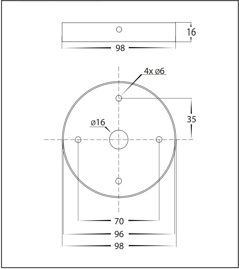
Mounting Base
Important Safety Issues
- This product must be installed by a qualified electrician according to AS/NZS 3000.
- Ensure all electrical mains are disconnected before any installation.
- Do not exceed maximum wattage restrictions for globes: 240V GU10 = 35w / 12V MR16 = 20w
- Modification of this product will void any warranty.
- Havit Lighting does not take responsibility for wrong installation, incorrect use, or use of installation material that does not belong to the system.
- When installing low voltage fittings, Voltage to fitting must be within +or- 5% of voltage required and cannot be installed more than 25m from LED Driver, if not within this allowance warranty will be voided.
- Aluminium and 304SS fittings must not be installed within 2km of any salt water environments.
- When installing copper fittings, gloves must be worn to avoid any oils transferring to fitting.
- All 316 stainless steel fittings must have regular cleaning maintenance to avoid any tea staining from forming on fitting. (Warranty does not cover Tea Staining)
- When installing surface mounted bollards, base plate must be installed on concrete or concrete pad, Fitting should not be installed under ground level, all holes including cable entry must be silliconed to prevent any water pentration into fitting, silicon must also be appiled around fitting at ground level. Failure to do this will void warranty
- All o-rings and seals must be in place correctly to maintain warranty.
- These instructions may be updated at any time due to product improvements, Please visit website for most current installation instructions.
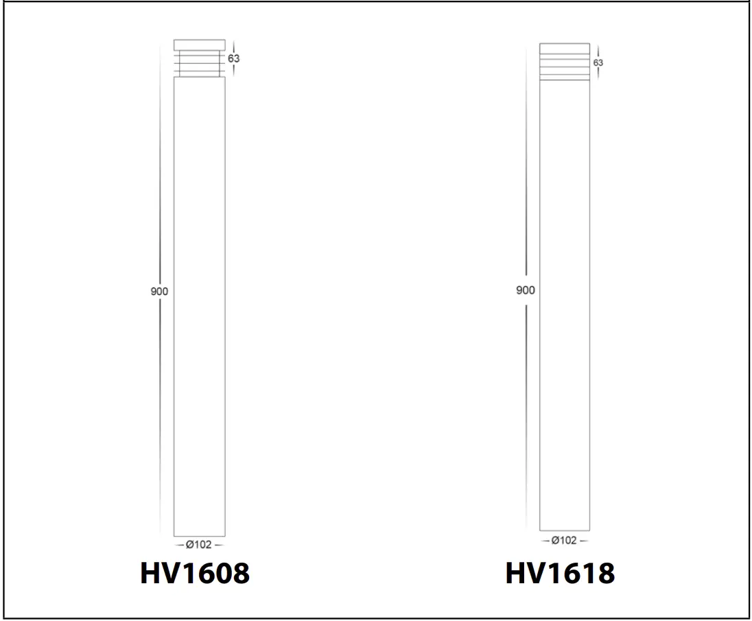
Dimensions
Steps for Installation
- Make sure that the electrical circuit is free of voltage (master switch off ).
- Remove 4x allen screws from side of fitting and put aside
- Install baseplate in desired location using apropriate screws for application. The screws supplied are mild steel which must be replaced with higher grade if there is any chance of them being affected by water. The location of baseplate must be installed on either concrete or concrete base and cannot be installed under ground level.
- Locate IP rated junction box within fitting. Undo screws from junction box and remove cover.
- Insert cable through cable gland on junction box. If your cable is not circular you must fix entry of your cable to maintain IP rating. Failure to do so will void warranty.
- Using an appropriate 12V DC LED driver – DO NOT CONNECT FITTING DIRECTLY TO 240V
- Connect live and neutral wires. If more than one fitting is installed, wiring must be done in parallel.
- Reattach cover to IP rated junction box making sure screws are tight and seals are still in place.
- Silicon all cable entry holes and fixing points on baseplate to avoid moisture penetration into fitting.
- Place bollard onto base plate and reattach 4x allen screws set aside earlier
- Colour temperature is set to 3000K. To change, remove cover from fitting by twisting anti clockwise. for HV1608 models, remove the 2x nuts and washers and put aside Remove globe by also twisting anti clockwise and select desired colour temperature by moving switch on side of globe and then reinsert globe.
- Reattach cover by turning clockwise or for HV1608 Models, reattach the 2x nuts first, making sure the seals are still in place and cover is tight to avoid any water penetration.
- All connections must be carried out carefully, inspect all contacts before switching back on the electric circuit.
Steps for Changing Globe
- Remove cover from fitting by twisting anti clockwise. for HV1608 models, remove the 2x nuts and washers and put aside Remove globe by also twisting anti clockwise.
- Re-insert the appropriate globe by twisting clockwise into the lamp holder (Make sure not to exceed max wattage, see product label for correct info)
- Reattach cover by turning clockwise or for HV1608 Models, reattach the 2x nuts first, making sure the seals are still in place and cover is tight to avoid any water penetration.
Product Specifications | ||||
| Model No. | HV1608T-BLK-240V | HV1608T-SS316-240V | HV1618T-BLK-240V | HV1615T-SS316-240V |
| Name | Maxi 900 | |||
| Material | 316 Stainless Steel | |||
| Colour | Black | Stainless Steel | Black | Stainless Steel |
| IP Rating | IP54 | |||
| Input Voltage | 240v AC | |||
| Lamp Base | E27 | |||
| Lamp Wattage | 1x 9w | |||
| Colour Temp | TRI Colour – 3000k, 4000k, 5500k | |||
| Lumens | 700lm, 720lm, 740lm | |||
| CRI | > 80 | |||
| Wiring | Parallel | |||
| Dimmable | No | |||
| Warranty | 2 Years Replacement* | |||
Mounting Base
Important Safety Issues
- This product must be installed by a qualified electrician according to AS/NZS 3000.
- Ensure all electrical mains are disconnected before any installation.
- Modification of this product will void any warranty.
- Havit Lighting does not take responsibility for wrong installation, incorrect use, or use of installation material that does not belong to the system.
- When installing low voltage fittings, Voltage to fitting must be within +or- 5% of voltage required, if not within this allowance warranty will be voided.
- Aluminium and 304SS fittings must not be installed within 2km of any salt water environments.
- When installing copper fittings, gloves must be worn to avoid any oils transferring to fitting.
- All 316 & 304 stainless steel fittings must have regular cleaning maintenance to avoid any tea staining from forming on fitting.
(Warranty does not cover Tea Staining) - All o-rings and seals must be in place correctly to maintain warranty
- When installing surface mounted bollards, base plate must be installed on concrete or concrete pad, Fitting should not be installed under ground level, all holes including cable entry must be silliconed to prevent any water pentration into fitting, silicon must also be appiled around fitting at ground level. Failure to do this will void warranty
- This form may be updated at any time due to product improvements, please check online installation form for most current version.
Dimensions
Steps for Installation
- Make sure that the electrical circuit is free of voltage (master switch off ).
- Remove 4x allen screws from side of fitting and put aside
- Install baseplate in desired location using apropriate screws for application. The screws supplied are mild steel which must be replaced with higher grade if there is any chance of them being affected by water. The location of baseplate must be installed on either concrete or concrete base and cannot be installed under ground level.
- Locate IP rated junction box within fitting. Undo screws from junction box and remove cover.
- Insert cable through cable gland on junction box. If your cable is not circular you must fix entry of your cable to maintain IP rating. Failure to do so will void warranty.
- Connect the cable using wire with earth. Connect earth first, then live and neutral wires.
- Reattach cover to IP rated junction box making sure screws are tight and seals are still in place.
- Silicon all cable entry holes and fixing points on baseplate to avoid moisture penetration into fitting.
- Place bollard onto base plate and reattach 4x allen screws set aside earlier
- Colour temperature is set to 3000K. To change, remove cover from fitting by twisting anti clockwise. Remove globe by also twisting anti clockwise and select desired colour temperature by moving switch on side of globe and then reinsert globe.
- Reattach cover by turning clockwise making sure the seals are still in place and cover is tight to avoid any water penetration.
- All connections must be carried out carefully, inspect all contacts before switching back on the electric circuit.
Steps for Changing Globe
- Open the cover by twisting anti-clockwise and remove lamp by twisting anti clockwise
- Re-insert the appropriate globe by twisting clockwise into the lamp holder (Make sure not to exceed max wattage, see product label for correct info)
- Attach covers by turning clockwise making sure the seals are still in place and caps are tight to avoid any water penetration.
Must be installed by a licensed electrician
Contact Details | |
| 143 Beauchamp Road Matraville NSW 2036 Australia | Tel: 02 9381 8300 Fax: 02 9666 8881 Email: [email protected] Web: www.havit.com.au |
Warranty Terms & Conditions* |
 |
Additional Information | |||
|  HV1608T-SS316-240V HV1608T-SS316-240V |  HV1618T-BLK-240V HV1618T-BLK-240V |
|