HAVACO ECH-NI PTX Electric Duct Heaters User Manual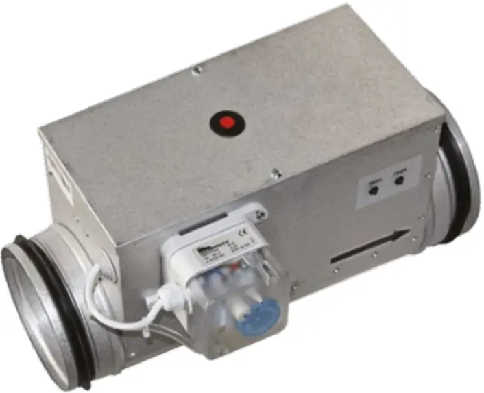
DESCRIPTION
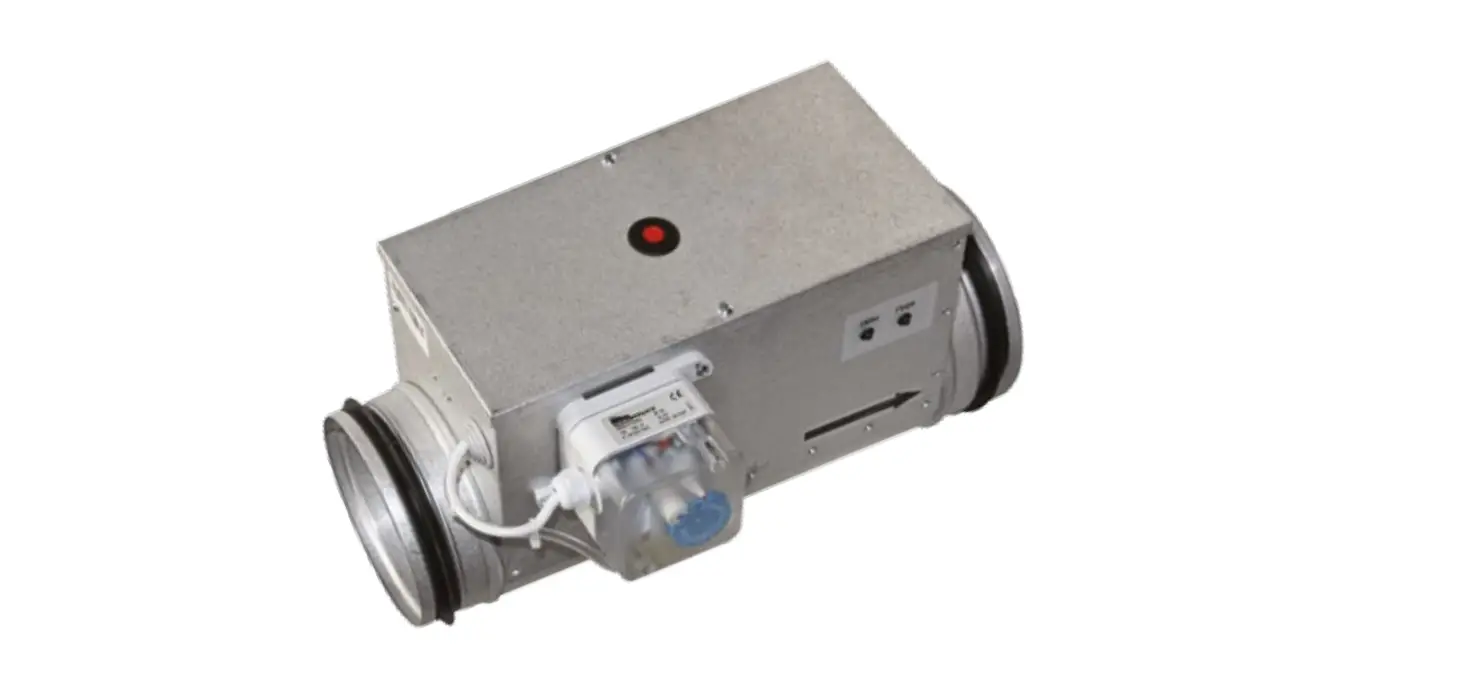
- Electric heaters are designed to heat clean air in ventilation systems.
- Casing is made from aluzinc coated steel which is high temperature proof.
- Heating elements tube is made from stainless steel ASI 304.
- In heaters are installed 2 protection thermostats, screw terminals for easy connection, microprocessial electrical heating controller, pressure switch, air flow sensor.
- Casing is with rubber seals for duct connection.
Maximum output air temperature 50°C.
Marking
- ECH NI PTX/PSX – aaa / b / xf
- aaa – Duct diameter [mm]
- b – Power [kw]
- x – Phases (1~230V, 2~400V, 3~400V)
TECHNICAL DATA
- All heaters are with 2 protection thermostats:
- Automatic reset – switch off temperature 50°C.
- Manual reset – cut off temperature 100°C
- Supply air temperature setpoint -10…50°C.
- Heaters have controller installed inside casing.
- Protection class IP 44.
[mm] [m3 /h] [V/50Hz] [kW] [A] 125 70 1~230 0,3/0,6/0,9/1,2 1,4/2,8/4,1/5,5 160 110 1~230
1~2300,3/0,6/0,9/1,2 1,4/2,8/4,1/5,5
2,8/4,1/5,5/9,1
13,2250 270 2~400
1~2300,6/0,9/1,2/2,0
54,5/5,5/9,1/13,5
13,2
8,7315 415 2~400
3~400
1~2301,0/1,2/2,0/3,0
5
6
1,0/1,2/2,04,5/5,5/9,1
13,2400 690 2~400
3~4005
6,0/9,0/12,08,7/13,0/17,3
TRANSPORTING
- All products are packed by producer for normal transporting conditions.
- For unloading and storing use proper lifter to prevent product damage.
- Do not lift product by power supply cable, automation components.
- Avoid impacts and impact loads.
- Until installation store products in dry place: Humidity 70% (20°C), temperature 5-40°C.
- Avoid long term storing. It is not recommended to store products more than 1 year
INSTALLATION
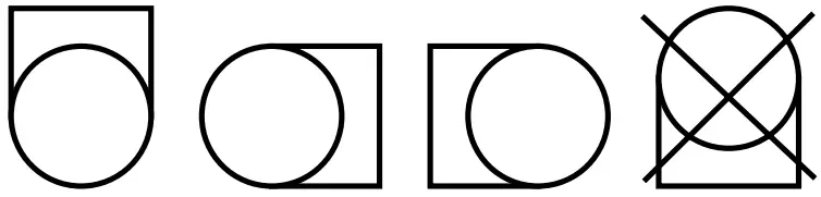
- • Heater can be installed in any position (see picture) except electrical connection box downward.
- If heater is installed in such way that can be accidental contact with heating elements, protective grill must be installed.
- Air flow through heater must be not less than 1,5 m/s.
- Heaters can’t be installed in explosive and aggressive atmosphere
- Heaters can be used only for clean air heating. It is recommended to install air filter (F) before heater.
- Heaters intended for inside installation.
- Casing and air duct before heater should be insulated with rock wool 10cm (R~2,4m²K/W).
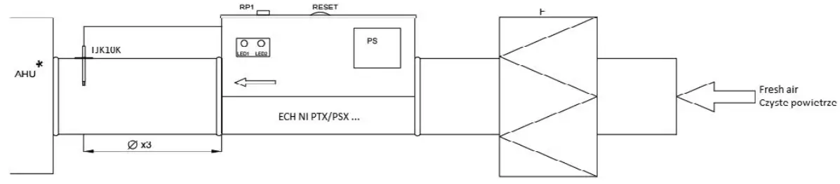
- Example of ECH NI PTX/PSX … heater installation


- F – filter for suplly air
- AHU with heat recovery
ELECTRICAL CONNECTION
- Electrical connection can be made only by qualified electrician, according to international and national installation standards.
- Power supply source must conform with data on heater label.
- Power supply cable must be selected corresponding to heater electrical data.
- Automatic circuit breaker must be selected corresponding to technical data table.
- Heater must be grounded.
- For heaters install duct temperature sensor and connect as in wiring diagram
SERVICE
- No special service is required for electrical heaters, only to check electrical connection, check if heating elements and PTX air flow sensor are clean not less than 1 time per year.
TROUBLESHOOTING
- No heating from heater
- Manual reset thermostat is cut off. Eliminate overheating cause, press „RESET“ button on heaters cover.
- No power supply to heater – check all external electrical connection components.
- Temperature sensor fault
- Check sensor resistance, it must be 10 kΩ at 25°C.
- Pressure switch fault
- Check if pressure in system is set correctly (check the pressure when air flow is not less than 1,5m/s).
- PCB fault
- Change PCB
- Heater gives full output, not by setpoint
- Temperature sensor fault. Check sensor resistance, it must be 10 kΩ at 25°C
- Air flow sensor fault. Check sensor resistance. It must be 22 Ω between X15..X16 and 10 Ω between X15..X18. Sensor must be clear
- Triac fault. Check triac conductance
- PCB fault. Change PCB
- Automatic circuit breaker switching off Protection thermostat cut off
- Check circuit breakers data, it must correspond to heaters electrical
data.- Check isolation of connection cables, wires, check is heater grounded.
- Check power supply source data, it must correspond to heaters electrical data
- Protection thermostat cut off
- Low air flow speed through heater. Check filters, fans, ducts of system.
- Pressure switch fault. Check if pressure in system is set correctly (check the pressure when air flow is not less than 1,5m/s)
INDICATION
LED1
Flashing 1 time per 3 seconds – EKR KN warming up (~30s). Flashing 1 time within second – EKR KN ready. Lit – Air flow sensor faul.
LED2
Lit – load is on (heating).
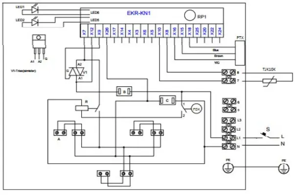
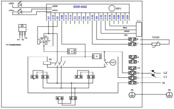
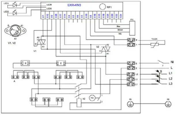
WIRING DIAGRAM
ELECTRICAL WIRING DIAGRAM MARKING
- Heating element
- Automatic reset overheating thermostat
- Manual reset overheating thermostat
- Switch
- K2 – Relay
- Relay
- Automatic circuit breaker
- Thermostat
- V1, V2 – Triac (simistor)
- EKR-KN – PCB
- RP1 – Supply air temperature setpoint
- TJK10K – Duct temperature sensor
- PSX – Pressure switch
- PTX – Air flow senso
- 1~230 Electrical connection

- 2~400 Electrical connection

- 3~400 Electrical connection

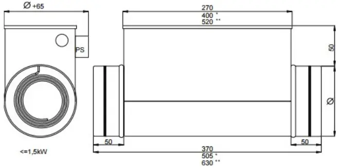
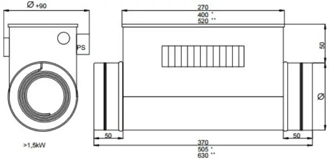
DIMENSIONS [mm]
- Dimensions for 12 kW heaters

- Dimensions for 15 kW heaters

CUSTOMER SUPPORT
Ventia Sp. z o.o.
ul. Słowikowskiego 81
05-090 Raszyn
tel.: (+48 22) 841 11 65
fax: (+48 22) 841 10 98
e-mail: [email protected]