SUNNY SF-B122049 Tryden Connected Magnetic Cycle Bike User Manual
IMPORTANT! Please retain owner’s manual for maintenance and adjustment instructions. Yoursatisfaction is very important to us, PLEASE DO NOT RETURN UNTIL YOU HAVE CONTACTED US: [email protected] or 1- 877 – 90SUNNY (877-907-8669).
IMPORTANT SAFETY INFORMATION
We thank you for choosing our product. To ensure your safety and health, please use thisequipment correctly. It is important to read this entire manual before assembling and usingtheequipment. Safe and effective use can only be achieved if the equipment isassembled,maintained, and used properly. It is your responsibility to ensure that all users of theequipmentare informed of all warnings and precaution
- Before starting any exercise program, you should consult your physician to determineif youhave any medical or physical conditions that could put your health and safety at riskor preventyou from using the equipment properly. Your physician’s advice is essential if youaretakingmedication that affects your heart rate, blood pressure, or cholesterol level.
- Be aware of your body’s signals. Incorrect or excessive exercise can damageyour health.Stop exercising if you experience any of the following symptoms: pain, tightness inyour chest,irregular heartbeat, shortness of breath, lightheadedness, dizziness, or feelingsof nausea.Ifyou do experience any of these conditions, you should consult your physicianbeforecontinuing with your exercise program.
- Keep children and pets away from the equipment. The equipment is designedfor adult useonly.
- Use the equipment on a solid, flat level surface with a protective cover for your floor or carpet.To ensure safety, the equipment should have at least 2 feet (60 CM) of free spaceall aroundit.
- Ensure that all nuts and bolts are securely tightened before using the equipment. Thesafetyofthe equipment can only be maintained if it is regularly examined for damage and/or wearandtear.
- Always use the equipment as indicated. If you find any defective components while assembling or checking the equipment, or if you hear any unusual noises comingfromtheequipment during exercise, discontinue use of the equipment immediately anddonot useuntilthe problem has been rectified.
- Wear suitable clothing while using the equipment. Avoid wearing loose clothing that maybecome entangled in the equipment.
- Do not place fingers or objects into the moving parts of the equipment.
- The maximum weight capacity of this unit is 245 pounds (110 KG).
- The equipment is not suitable for therapeutic use.
- To avoid bodily injury and/or damage to the product or property, proper lifting andmovingarerequired.
- Your product is intended for use in cool and dry conditions. You should avoid storageinextreme cold, hot or damp areas as this may lead to corrosion and other relatedproblems.
- This equipment is designed for indoor and home use only; it is not intendedfor commercialuse.
PRE-ASSEMBLING
Before you start to assemble, please make sure all parts are included.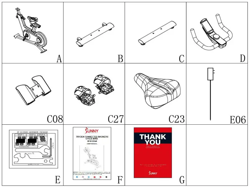
| No. | Description | Spec. | Qty. | No. | Description | Spec. | Qty. | |
| A | Main Frame | 1 | C23 | Seat | 1 | |||
| B | Front Stabilizer | 1 | E06 | Power Adapter | 1 | |||
| C | Rear Stabilizer | 1 | E | Hardware Package | 1 | |||
| D | Handlebar | 1 | F | Manual | 1 | |||
| C08 | Bottle Holder | 1 | G | Thank You Card | 1 | |||
| C27L/R | Pedal Set L/R | 2 |
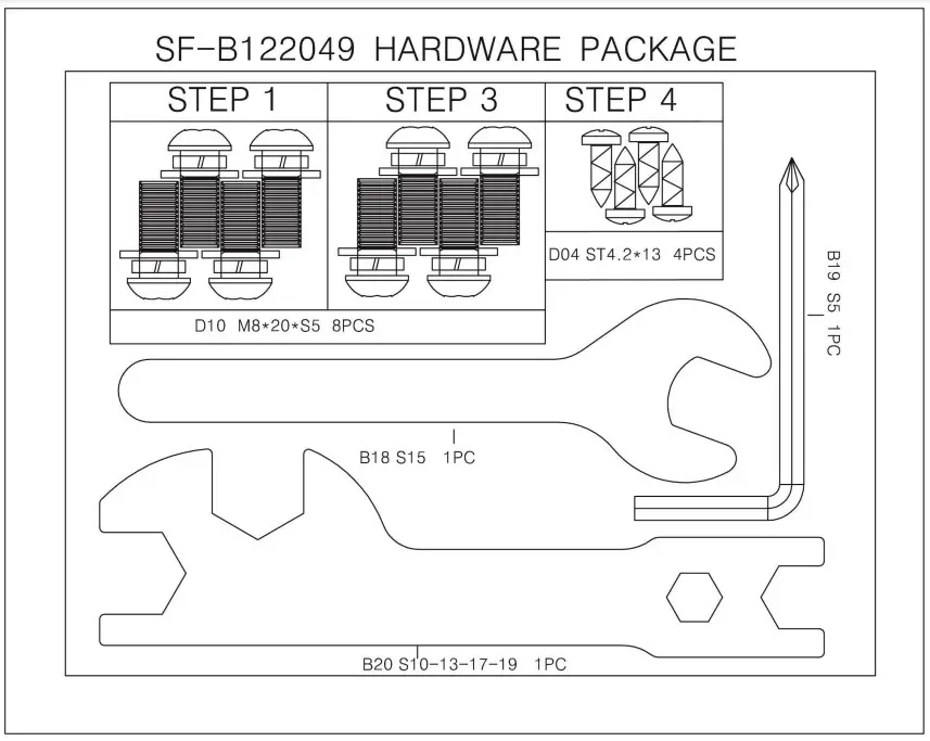
HARDWARE PACKAGE
Ordering Replacement Parts (U.S. and Canadian Customers only)
Please provide the following information in order for us to accurately identify the part(s) needed:
- The model number (found on cover of manual)
- The product name (found on cover of manual)
- The part number found on the “EXPLODED DIAGRAM” and “PARTS LIST” (foundneartheend of the manual)
Please contact us at [email protected] or 1- 877 – 90SUNNY(877-907-8669).
ASSEMBLY INSTRUCTIONS
We value your experience using Sunny Health and Fitness products. For assistance with partsor troubleshooting, please contact us at [email protected] 1-877-90SUNNY(877- 907-8669)
STEP 1: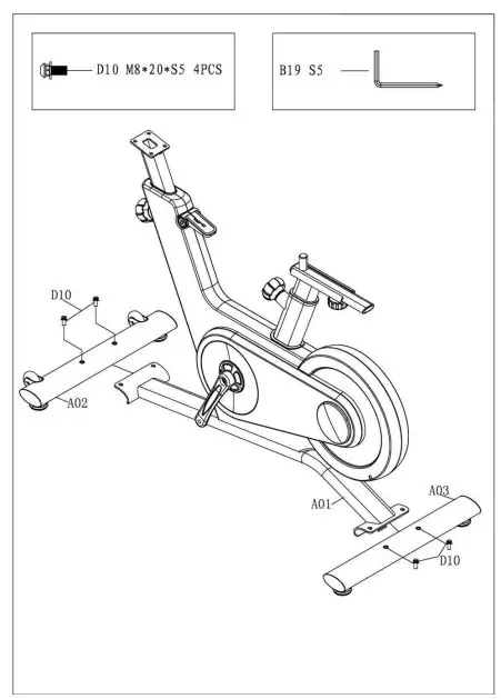
Attach the Front & Rear Stabilizers(No. A02&No.A03) to the Main Frame (No. A01) byusing4Bolts(No. D10). Tighten and secure withAllenWrench(No. B19)
STEP 2: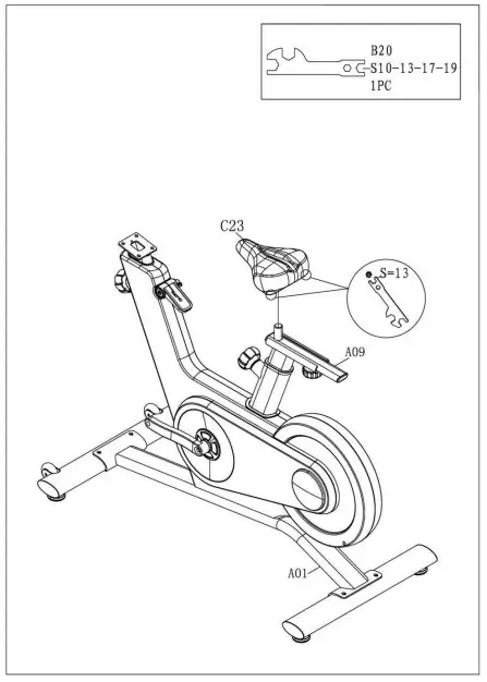
Secure Seat (No. C23) to Seat Slider Tube(No.A09)with Spanner (No. B20).
We value your experience using Sunny Health and Fitness products. For assistance with partsor troubleshooting, please contact us at [email protected] 1-877-90SUNNY(877- 907-8669)
STEP 3: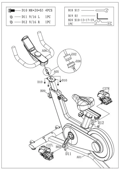
WARNING! Read instructions carefullyasimproperassembly may cause permanent damage toyourbike
Loosen and pull the Circular Knob(No. B09)outward. Raise the Upright Tube (No. A05) andpayattention to the protection of MiddleSingleWire(No. E08) to avoid falling into the tube. ConnecttheTop Single Wire (No. E02) with theMiddleSingleWire (No. E08).
Attach Handlebar (No. A06) onto theUprightTube(No. A05) by using 4 Bolts (No. D10). Tightenandsecure with Allen Wrench (No. B19).
Remove the Nylon Nut L&R(No. D11&D12)located on the Pedal Set L/R(No. C27L/R). TheNylon Nut L (No. D11) is blue on theinside. TheNylon Nut R (No. D12) is white ontheinside. ThePedal Set L/R (No. C27L/R) are labeledLandR.
Align the Left Pedal Set L (No. C27L) withtheLeftCrank Arm (No. B02) at 90°. ScrewtheLeftPedalSet L (No. C27L) counter-clockwiseintoLeft CrankArm (No. B02).Once screwed in place, usetheSpanner (No. B18) to tighten securely. Then screwNylon Nut L (No. D11) clockwise intothethreadendof the Left Pedal Set L (No. C27L). SecurewithSpanner (No. B18 & B20)
Align the Right Pedal Set R(No. C27R) withtheRight Crank Arm (No. B03) at 90°. Screw theRightPedal Set R (No. C27R) clockwise intoRightCrankArm (No. B03). Once screwed in place, usetheSpanner (No. B18) to tighten securely. ThenscrewNylon Nut R (No. D12) counter-clockwiseintothethread end of the Right Pedal Set R(No. C27R).Secure with Spanner (No. B18 &B
We value your experience using Sunny Health and Fitness products. For assistance with partsor troubleshooting, please contact us at [email protected] 1-877-90SUNNY(877- 907-8669)
STEP 4: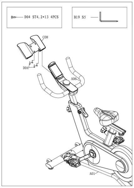
Attach the Bottle Holder (No. C08) totheHandlebar (No. A06) by using the 4S crews (No.D04). Tighten and secure with AllenWrench(No.B19)
STEP 5: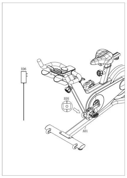
Insert the Power Adapter (No. E06) intothePower Wire (No. E05) .
The assembly is complete!
ADJUSTMENTS & USAGEGUIDE
ADJUSTING THE BALANCE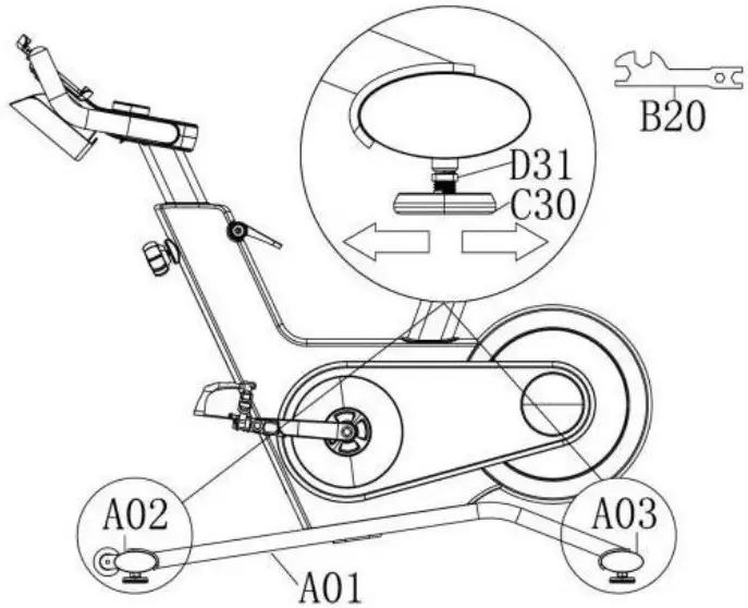
In order to achieve a smooth and comfortableride, youmustensure that the stability of the bike is secured. If younoticethatthebike is unbalanced during use, you should adjust the4FootPads(No. C30) located beneath the Front & Rear Stabilizers(No.A02& No. A03) of the bike. To do so, use Spanner (No. B20) toloosenNut (No. D31) by turning it clockwise. With the nut loosened,rotatethe Foot Pads (No. C30) until it sits level with thesurfacethatthebike is on. When you have finished adjusting the Foot Pads(No.C30), use Spanner (No. B20) to re-tighten theNut (No. D31)byturning it counter-clockwise.
ADJUSTING THE SEAT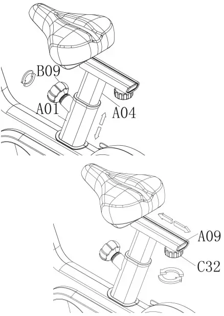
The seat of this bike is fully adjustable as it movesUp, Down,Fore(forward), After (backward).
To adjust the height of the Seat Post (No. A04), loosenandpullthe Circular Knob (No. B09) outward, then raiseor lowertheseatto the desired height. Once adjusted, re-insert andtightentheCircular Knob (No. B09) to secure the seat in place.
To adjust the seat back and forth, loosen the Seat Knob(No.C32)outward, then slide the Seat Slider Tube (No. A09) tothedesiredposition. Once positioned, re-tighten the Seat Knob(No. C32)tosecure the seat slider tube in place
ADJUSTING THE HANDLEBAR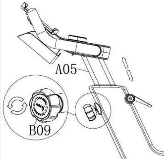
It is important that the handlebar and seat arebothset tothecorrect height to your body. To adjust the handlebar height, loosenand pull the Circular Knob (No. B09) outward, thenslidetheUpright Tube (No. A05) up or down to the desiredheight.Onceadjusted, re-insert and tighten the Circular Knob(No. B09)tosecure the handlebar in place
PEDAL STRAP ADJUSTMENT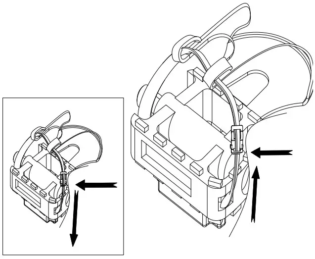
Your feet should be secured in the toe clips duringexercise. Placeyour feet as far forward into the toe clips as you can. Withyourfeetin place, turn the crank to bring one foot to withinarm’sreach,grasp the pedal strap and pull it upward to tightenthetoe clipc age.Then insert the strap back into the hoop of the toeclip. Repeatthisprocess to secure your other foot.
EMERGENCY BRAKE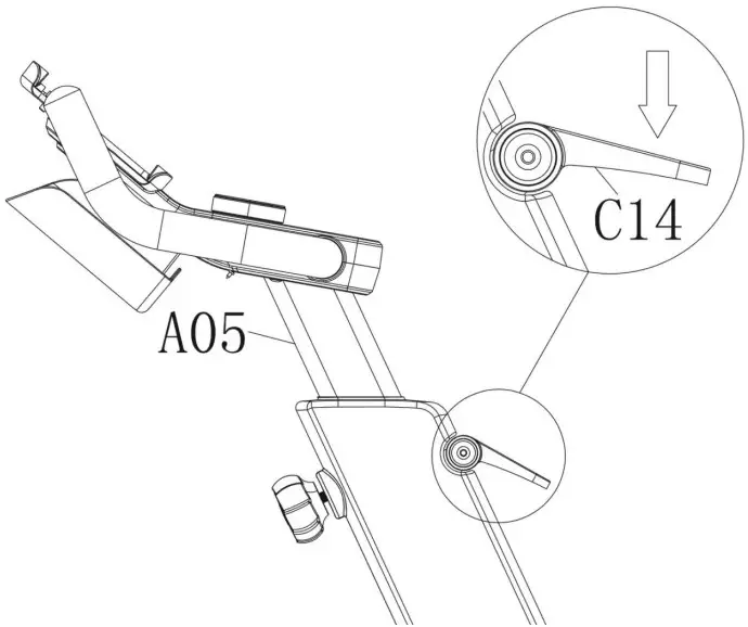
During use, users can stop the bike completely by pushingdownon the Brake Handle (No. C14). Pushing down ontheBrakeHandle (No. C14) will enforce the brake and bring thebiketoanimmediate stop
Child Safety Lock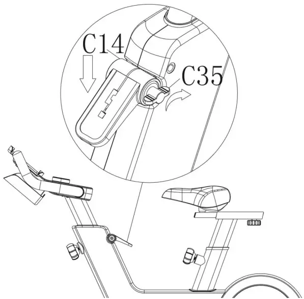
When you finish exercising, users can use the ChildSafetyLock(No. C35) to stop the bike from moving. PressingdowntheBrakeHandle (No. C14) and then tighten the Child SafetyLock(No.C35) clockwise
TRANSPORTING THE BIKE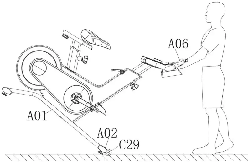
To move the bike, stand at the front of the bikesothat you’redirectly in front of the handle bar. Firmly grasp andholdeachsideofthe handlebar, place one foot on the Front Stabilizer(No.A02)and tilt the bike towards you until the 2 TransportationWheels(No. C29) touch the ground. With the TransportationWheels(No.C29) on the ground, you can transport the biketothedesiredlocation with ease.
NOTE: When moving the bike, always use cautionasunexpectedimpact, such as dropping the bike, may cause injuryandaffectthebike’s operation.
DISMOUNTING WARNING:
For your safety, it is recommended that you never attempt to dismount or removeyour feet fromthepedals until both the flywheel and pedals/cranks have come to a complete stop. Failuretofollowthis recommendation may lead to loss of control and/or serious injury.
Here are a few examples of how to safely dismount the bike
- Reduce the pedal speed until the pedals/crank come to a complete stop.
- Increase the resistance until the pedals/crank come to a complete stop.
- Push and hold the Brake Handle (No. C14) down until the pedals/crank come to acomplete stop
IMPORTANT ELECTRICAL INFORMATION
WARNING: This bike requires a power source of 1 amp (100-240V) in order to properly operate. For your safety, as well as the safety of others, please verify that the power sourceiscorrect before plugging in the equipment. Any power source above or below this level couldcause significant damage to the equipment and or user
EXERCISE CONSOLE
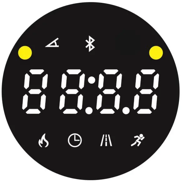
FUNCTION BUTTONS:
Display Switch Button:
Short press the Console (No. E01) to change the display mode;
Long press the Console (No. E01) for 3 seconds to reset all value to zero.
Adjust the resistance:
Turn the Console (No. E01) clockwise, increase the resistance value from1 to 16. Turn the Console (No. E01) counter-clockwise: reduce the resistance value from16to1. When adjusting the resistance, console will display resistance value.
When staying on the resistance value, short press the Console (No. E01) to show other display
FUNCTIONS
Display: Cycles through all Functions: Calories-Time-Distance-Speed Resistance.
 Display current resistance “1,2,3,…,16”.
 Display the calories has consumed. Accumulate total calories from 0.0 to 999.9.
 Display the time has run. Accumulates total time from 00:00 to 99:59.
 Display the distance has run. Accumulates total distance from 0.0 to 99.9 Miles.
 Display current speed from 0.0 to 72.0 MPH.
 When connected with Bluetooth, Display Bluetooth connected
APP CONNECTION
- Scan the QR code below to download the SunnyFit app onto your mobile device.

- If this is your first time using the SunnyFit app, follow the in-app instructions to registerforyour free SunnyFit account and log in.
- Ensure that the Bluetooth
 function is turned on fromyour mobiledevice.
 - To connect the equipment to the SunnyFit app
- a) From the “Workout” tab, press on the “Search” button to search for your equipment.
- b) Once your equipment appears on the list, tap the “Select” button to confirm.
- c) Note: If your equipment does not appear on the “Searching for Equipment” list, checkthe CONSOLE on your equipment to ensure that it is not in sleep modeandyourphone’s Bluetooth function is on, then tap “Retry” to search again.
- d) Once your equipment shows up on the “Workout” tab as “Currently Selected”, yourequipment is now ready to display, track, and record your equipment’s workout statson the app!
- If you are unable to replicate these steps, or have any other issues with the Sunny Fit app,please contact SunnyFit support at [email protected], or use the in-app“Contact Us”form to request support (“Me” tab -> “Contact Us”)

MAINTENANCE INSTRUCTIONS
This is general information for daily, weekly and monthly maintenance to be performed on your bike
DAILY MAINTENANCE
After each exercise session, wipe down all the equipment: seat, frame, and handlebars. Pay special attention to the seat post, handlebar post, and belt/chain guard. Sweat is very corrosive and may cause problems that require parts replacement later.
- Get on the bike and engage the drive train.
- Pay attention to any vibrations felt through the pedals. If you feel any vibrations, you may need to tighten the pedals, bottom bracket, or adjust the drive belt/chain tension.
- Use a wrench to tighten the pedals until they are secure
WEEKLY MAINTENANCE
- Inspect moving parts and tighten the hardware.
- Inspect pull pin frame fittings to make sure the fittings are secured. Loose frame fittings may strip out threads over time and cause extensive damage.
- Clean and lubricate pop pin assemblies. Pull on the pin and spray a small amount of lubricant onto the shaft.
- Tighten the seat hardware to make sure the seat is level and centered.
- Brush and treat the resistance pads. Remove any foreign material that may have collected on the pads. Spray the pads with silicone lubricant. This helps to reduce noise from friction between the pads and the flywheel.
- Visually inspect the bottom bracket, toe clips and toe straps. If any of them are loose or disconnected, attach and tighten.
MONTHLY MAINTENANCE
- Check if all hardware is secure, suchas:waterbottle holder, flywheel nuts, belt/chainguardbolts, brake caliper lock nuts andbrakecalipertension rod nuts.
- Inspect the brake tension rodfor signsofwearsuch as missing threads. Clean and lubricatethe brake tension rod.
- Clean and lubricate the seat post, handlebarpost and seat slider. Remove any build up offoreign material.
LEATHER BRAKE PADCARE(IFApplicable)
- Perform this maintenance whenthebrakepadis first installed and for thelifeof the brakepad. Following these simpleguidelinescanincrease the life of your brakepads.
- Some brake pad assembliesarepre-lubricated. Squeeze thebrakepad.Iflubricant is released, then thepadhasbeenpre-lubricated.
- If the brake pad is dry, then coat thebrakepadwith 3-n-1 oil. Brush the leather withaclean,wire bristle brush, and thenapplytheoil.Theoil should be allowed to soakintothepad.Repeat 4-5 times until the padissaturated,butnot dripping with oil. When thepadissaturated, it will no longer absorboil.
- Inspect the brake pad weeklyandlubricateifneeded. The pad should not have aglazedappearance. If the pad appearsglazed,thenbrush it with wire brush and applylubricantasneeded. If any of the spongepaddingisshowing through the leather pad, thebrakepad should be replaced.
NOTE: If you are unable to resolve an issue using the troubleshooting guideabove, pleasecontact Customer Service at [email protected]
EXPLODED DIAGRAM
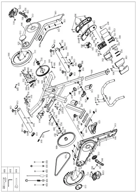
PARTS LIST
| No. | Description | Spec. | Qty. | No. | Description | Spec. | Qty. | |
| A01 | Main Frame | 1 | C10 | Right Chain Cover | 1 | |||
| A02 | Front Stabilizer | 1 | C11 | Big Flywheel Cover | 2 | |||
| A03 | Rear Stabilizer | 1 | C12 | Small Flywheel Cover | 2 | |||
| A04 | Seat Post | 1 | C13 | Crank Cover | 2 | |||
| A05 | Upright Tube | 1 | C14 | Brake Handle | 1 | |||
| A06 | Handlebar | 1 | C15 | Brake Handle Cover | 1 | |||
| A07 | Brake Plate | 1 | C16 | Upright Sleeve | 1 | |||
| A08 | Magnetic Plate | 1 | C17 | Seat Sleeve | 1 | |||
| A09 | Seat Slider Tube | 1 | C18 | Wolly Felt Bracket | 1 | |||
| A10 | Spring Plate | 1 | C19 | Oval Plug | 4 | |||
| A11 | Belt Pulley | 1 | C20 | Seat Bushing | 1 | |||
| A12 | Adjusted Plate | 1 | C21 | Rubber Ring | 1 | |||
| B01 | Magnet | 8 | C22 | Magnet Bracket | 1 | |||
| B02 | Left Crank Arm | 1 | C23 | Seat | 1 | |||
| B03 | Right Crank Arm | 1 | C24 | Brake Cable | 1 | |||
| B04 | D-Shape Fixed Axis | 1 | C25 | Belt | 1 | |||
| B05 | Flywheel Spindle | 1 | C26 | Plastic Button | 7 | |||
| B06 | Flywheel | 1 | C27L/R | Pedal Set L/R | 2 | |||
| B07 | Ball Plug | 2 | C28 | Oval Pad | 2 | |||
| B08 | Bearing Sleeve | 1 | C29 | Transportation Wheel | 2 | |||
| B09 | Circular Knob | 2 | C30 | Foot Pad | 4 | |||
| B10 | Knob Nut | 2 | C31 | Motor Cable | 1 | |||
| B11 | Knob Plate | 2 | C32 | Seat Knob | 1 | |||
| B12 | Bearing | 6203-ZZ | 2 | C33 | Wolly Felt | 1 | ||
| B13 | Bearing | 6001-2RS | 2 | C34 | Rubber Plate | 2 | ||
| B14 | Tighten Bolt | 2 | C35 | Child Safety Lock | 1 | |||
| B15 | Tension Spring | 4 | C36 | Crank Cover | 2 | |||
| B16 | Brake Spring | 2 | D01 | Screw | ST2.2*6.5 | 10 | ||
| B17 | Seat Slider Plate | 1 | D02 | Screw | ST2.9*7 | 12 | ||
| B18 | Spanner | S15 | 1 | D03 | Screw | ST3.5*10 | 5 | |
| B19 | Allen Wrench | S5 | 1 | D04 | Screw | ST4.2*13 | 26 | |
| B20 | Spanner | S10-13-17-19 | 1 | D05 | Screw | ST4.2*12 | 4 | |
| C01 | Device Holder Upper Plate | 1 | D06 | Big Flat Washer | Φ8*Φ20*1.5 | 3 | ||
| C02 | Device Holder Lower Plate | 1 | D07 | Big Flat Washer | Φ5*Φ10*1.5 | 2 | ||
| C03 | Device Holder | 1 | D08 | Bolt | M5*15 | 1 | ||
| C04 | Plastic Support Plate | 2 | D09 | Nut | M5 | 1 | ||
| C05 | Console Top Cover | 1 | D10 | Bolt | M8*20*S5 | 8 | ||
| C06 | Console Bottom Cover | 1 | D11 | Nylon Nut L | 9/16 L | 1 | ||
| C07 | Silicone Pad | 1 | D12 | Nylon Nut R | 9/16 R | 1 | ||
| C08 | Bottle Holder | 1 | D13 | Bolt | M6*12 | 1 | ||
| C09 | Left Chain Cover | 1 | D14 | Bolt | M5*10 | 10 | ||
| D15 | Spring Washer | Φ17 | 2 | D31 | Nut | M10 | 4 | |
| D16 | Spring Washer | Φ12 | 2 | D32 | Screw | ST4.2*12 | 3 | |
| D17 | Nut | M10*1 | 2 | D33 | Bolt | M6*25 | 1 | |
| D18 | Nut | M8*H7 | 1 | D34 | Flat Washer | Φ4*Φ8*1.5 | 1 | |
| D19 | Nut | M6 | 1 | D35 | Wave spring washer | Φ21xΦ17.5×0.3t | 1 | |
| D20 | Nut | M6 | 3 | D36 | Big Flat Washer | Φ8*Φ20*1.5 | 1 | |
| D21 | Bolt | M6*32*S5 | 2 | E01 | Console | 1 | ||
| D22 | Bolt | M10*1.25 | 2 | E02 | Top Signal Wire | L=150mm | 1 | |
| D23 | Bolt | M6*45 | 1 | E03 | Bottom Signal Wire | L=260mm | 1 | |
| D24 | Pin | 1.2*20 | 1 | E04 | Sensor | 1 | ||
| D25 | Bolt | M8*30*S6 | 1 | E05 | Power Wire | L=150mm | 1 | |
| D26 | Flat Washer | Φ6*Φ18*1.5 | 1 | E06 | Power Adapter | L=1900mm | 1 | |
| D27 | Nut | M6 | 7 | E07 | Motor | 1 | ||
| D28 | Nut | M8 | 2 | E08 | Middle Signal Wire | L=800mm | 1 | |
| D29 | Bolt | M6*45 | 1 | E09 | Bluetooth Wire | L=150mm | 1 | |
| D30 | Bolt | M8*16*S6 | 2 | |||||
CONNECT WITH US
FOR FITNESS ARTICLES, VIDEOS & WORKOUTS
![]() @SUNNYHEALTHANDFITNESS
@SUNNYHEALTHANDFITNESS![]() @SUNNYHEALTHANDFITNESS
@SUNNYHEALTHANDFITNESS![]() @SUNNYHEALTHFITNES5
@SUNNYHEALTHFITNES5![]() @SUNNYHEALTHFIT
@SUNNYHEALTHFIT![]() @SUNNYHEALTHFITNESS ISUNNYHEALTHANDFITNESS
@SUNNYHEALTHFITNESS ISUNNYHEALTHANDFITNESS![]() @SUNNYHEALTHFITNESS
@SUNNYHEALTHFITNESS