![]() IT Controller (used 4G/ 3G/ GSM Communication)
IT Controller (used 4G/ 3G/ GSM Communication)
JRN-430K
User Manual
Doc# : LE-209529
Ver.1.01
Date: Jan. 25, 2021
@Copyright
JRC Mobility Inc.
Locator Products Groupe
Product Development Department
History
| Date | Number | The contents of the change |
| Dec. 07, 2020 | 1.00 | |
| Jan. 25, 2021 | 1.01 | 1.1 Overview 4.4 4G/3G/GSM module Specification addition The following bands of LTE are not used in the United States: Bd1, Bd7. |
Introduction
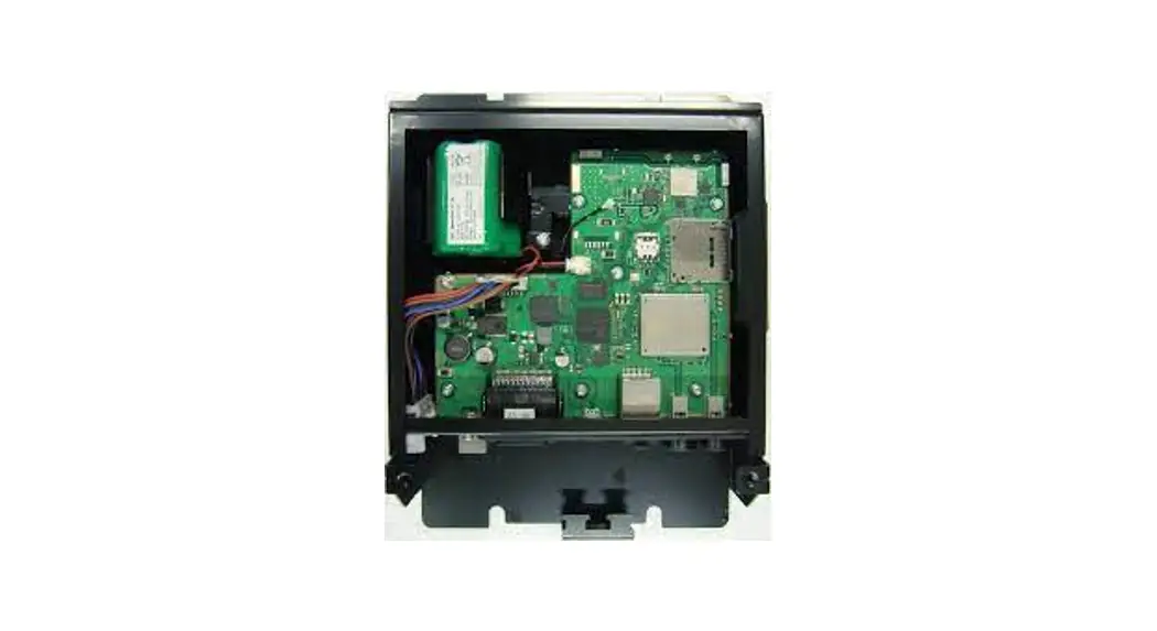
IT Controller (used 4G/3G/GSM Communication) JRN-430K is a vehicle small terminal to has the GPS measurement function and 4G/3G/GSM communication function and uses it for management and positional information track/theft pursuit etc. of the vehicle. (JRN-430K is a device dedicated to specific customers and will not be sold to the general public.) As a communications protocol, TCP/IP are mounted. The terminal made by the Gemalto product’s PLS62-W is installed.
Overview
The main specification is presented as follows.
| No. | Items | Specification | Remarks |
| 1 | Communication module | 4G/3G/GSM Communication module (PLS62-W Gemalto Product) LTE: Twelve band, 700 (Bd12 <MFBI Bd17>, Bd28) 800 (Bd18, Bd19, Bd20) 850 (Bd5) / 900 (Bd8) / AWS (Bd4) / 1800 (Bd3) / 1900 (Bd2) / 2100 (Bd1) / 2600 (Bd7) UMTS/HSPA+: Seven band, 800 (Bd19) / 850 (Bd5) / 900 (Bd8) / AWS (Bd4) / 1800 (Bd9) / 1900 (Bd2) / 2100MHz (Bd1) GSM/GPRS/EDGE: Quad band, 850/900/1800/1900 MHz | The following bands of LTE are not used in the United States: Bd1, Bd7. |
| 2 | Data transfer rate | GPRS: Multislot Class 12 EGPRS: Multislot Class 12 | |
| 3 | Communication Antenna | 7ABLE0009 (FAKRA) (Nippon Antenna) | |
| 4 | GPS Antenna | NAY-3930G | |
| 5 | Internal Battery | NBB-1300 (1300mAh/6.0V) | |
| 6 | Current and Voltage | DC+20V to +32V 400mA max or less /24V Waiting mode: 17mA or less /24V |
Composition
| NO. | Equipment | Model | Quantity |
| 1 | IT Controller | JRN-430K | 1 |
| 1-1 | Communication Module | PLS62-W Gemalto Product | 1 |
| 1-2 | Battery pack | NBB-1300 | 1 |
| 2 | GPS Antenna | NAY-3930G | 1 |
| 3 | 4G/3G/GSM Communication antenna | 7ABLE0009(FAKRA) (Nippon Antenna) | 1 |
(Note#1)
Please prepare the IF cable by the visitor side.
(Note#2)
A connection I/F cable requires a fuse because of over-current protection.
Please insert the fuse in three places a battery, GND, and ACC.
(Note#3)
Please do not take a power supply from the DC cigar socket.
It becomes the cause that operation is poor, according to a bad connection.
Function
- Operation in ACC OFF executes the following.
-1. Send data at regular intervals.
-2. Respond to calls from the server.
-3. Acquisition of information on the actual location by GPS, and Generation of warning outside area. - Storage of operation data
- Timer Even if the main source of power is cut, the date and time are maintained.
- Backup The re-charge battery is installed. Even if it disconnects a power supply, the operational mode and network transmission setting of IT controller is held.
- Serial communication ports Connection I/F (CAN), 115200bps(monitor)
- GPS function Present location is acquired. (WGS84)
- 4G/3G/GSM communication
- Software rewriting function A software rewriting is done by using the Ethernet.
- Serial communications with the external equipment are done by serial commands.
1) Key ON
2) Engine ON
3) Key OFF
4) Alarm
5) Fuel residual quantity
6) Engine amount of water
7) Engine oil level
8) Hydraulic oil level
9) Engine oil pressure
10) Engine water temperature
11) Air cleaner
12) Charge
13) DS (compulsive key OFF)
14) RT (the present state inquiry)
15) HS (foxtail millet meter change)
16) CO (command)
17) Automatic key-off judging processing - Communication protocol It transmits to the mail server by e-mail.
- Time Zone Setting UTC+α and operating.
- WiFi communication Enables communication at 2.4 / 5GHz by IEEE802.11g / n. WiFi supports AP mode. The maximum number of devices that can connect to WiFi at the same time is two. Connect a network camera or smartphone to WiFi for use.
- Bluetooth communication Communication by Bluetooth 4.2 is possible. Only one device can be connected to Bluetooth at the same time. HFP is installed as a voice profile and GATT is installed as a data communication profile. Connect a smartphone (BLE compatible) and a microphone to Bluetooth for use.
- Ethernet communication (100Base-T) Enables full-duplex communication using CAT5e Ethernet cable.
- SD card interface Allow SDHC cards (class 10) of 4GB or more to be used. The SDHC card stores network camera images, microphone audio, CAN communication LOG, etc.
- USB interface It supports USB2.0 and supports USB Host and Device functions. USB is used by connecting to a webcam, USB microphone, USB memory, and PC (serial communication). It supports OTG. No USB authentication is required.
- Camera connection It is possible to connect to a network camera using the Ethernet port and WiFi. It is possible to connect to a webcam using the USB port.
Product specification
Common Specification
| NO. | Items | Specification performance |
| 1 | Power supply voltage | DC+20V to +32V |
| 2 | Battery pack | NiMH rechargeable battery NBB-1300 (1300mAh/6.0V) |
| 3 | SIM Interface | 1.8V / 3.0V |
| 4 | Current | Communication state : max current Less than 400mA / 24V (+25°C) Standby state: max current Less than 17mA (+25°C) (When not charging the battery) |
| 5 | Circumference environment | Operation: -30°C to +70°C Preservation: -40°C to +80°C Humidity of operation: 0% to 90% (don’t dew) At use in battery,+ Operation: -20°C to +70°C 0°C to +70°C of the charge operates. |
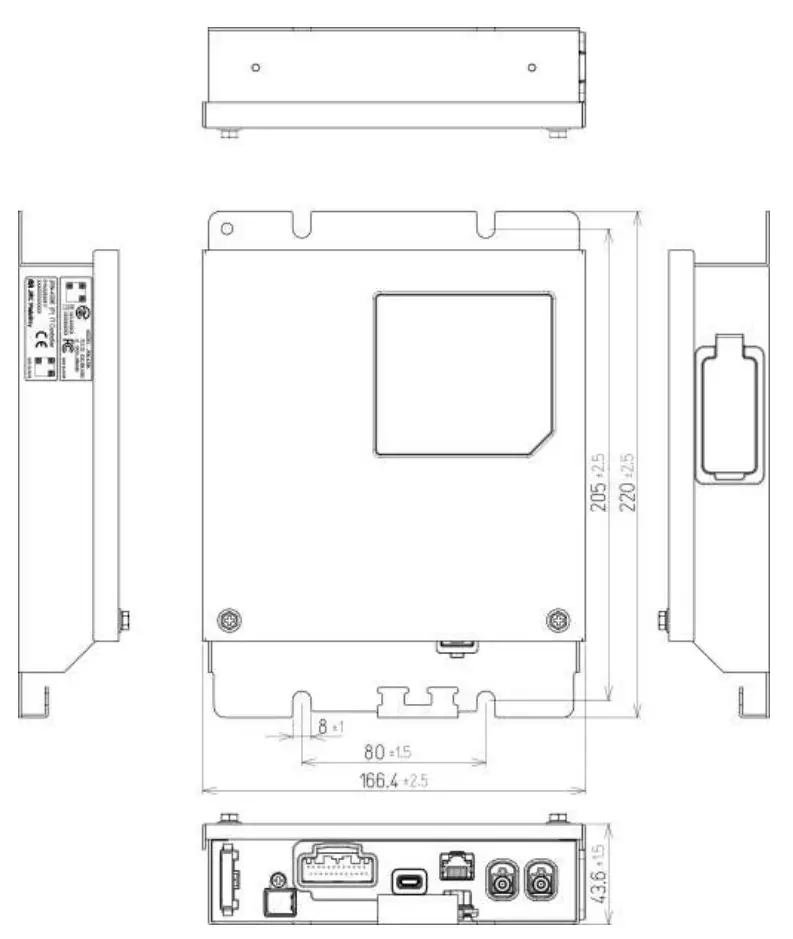
| 6 | Dimension | W 166.4mm x L 220.0mm x H 43.6mm |
| 7 | Weight | 1,500g or less |
| 8 | Case material | SPCC |
Serial Interface Specification
A. DTE CAN (Standard)
| NO. | Items | Specification performance |
| 1 | Data transmission | SAE J1939 |
| 2 | Speed | 125 / 250 / 500 kbps For excavators: Depends on terminal settings. For cranes: Depends on software settings. |
| 3 | Communication format | Extension 29 bit |
| 4 | Switch to the RS-232C | By the chip jumper change |
B. DTE RS-232C (Standard)
| NO. | Items | Specification performance |
| 1 | Data transmission | Half-duplex start-stop synchronization |
| 2 | Signal level | RS-232C |
| 3 | Speed | 4800 bps |
| 4 | Frame length | Variable-length |
| 5 | Data length | 8 bit |
| 6 | Start bit | 1 bit |
| 7 | Parity bit | None |
| 8 | Stop bit | 1 bit |
| 9 | Character code | EUC |
C. DTE CAN (2nd system)
| NO. | Items | Specification performance |
| 1 | Data transmission | SAE J1939 |
| 2 | Speed | 125 / 250 / 500 kbps For excavators: Depends on terminal settings. For cranes: Depends on software settings. |
| 3 | Communication format | Extension 29 bit |
| NO. | Items | Specification performance |
| 1 | Data transmission | Half-duplex start-stop synchronization |
| 2 | Signal level | RS-232C |
| 3 | Speed | 4800 bps |
| 4 | Frame length | Variable-length |
| 5 | Data length | 8 bit |
| 6 | Start bit | 1 bit |
| 7 | Parity bit | None |
| 8 | Stop bit | 1 bit |
| 9 | Character code | EUC |
Console(Debug)
| NO. | Items | Specification performance |
| 1 | Data transmission | Half-duplex start-stop synchronization |
| 2 | Signal level | RS-232C |
| 3 | Speed | 115200 bps |
| 4 | Frame length | Variable-length |
| 5 | Data length | 8 bit |
| 6 | Start bit | 1 bit |
| 7 | Parity bit | None |
| 8 | Stop bit | 1 bit |
| 9 | Character | EUC |
GPS Receiver Specification
| NO. | Items | Specification performance |
| 1 | Model | 7DLTS0104 (GPS10) (JRC product) |
| 2 | Receiving system | Max 23hannel (high-speed search channel) |
| 3 | Received frequency | 1575.42MHz (L1), C/A code |
| 4 | Land survey system | WGS-84 (Default) |
| 5 | Time system | UTC |
| 6 | Positioning accuracy Position Speed Direction | 5.3m 2DRMS 0.04m/sec. RMS Less than 0.14° RMS (Speed 60km/h) |
| 7 | Speed | 1 sec typ. |
| 8 | T.T.F.F (Without signal discontinuation) Open skies | Hot start: 3s typ. / 15s max. Warm start: 33s typ./ 55s max. Cold start: 35s typ./ 60s max. |
4G/3G/GSM module Specification
| NO. | Items | Specification performance |
| 1 | Model | Cinterion PLS62-W (Gemalto product) |
| 2 | Frequency Band | GSM/GPRS/EDGE: Quad-band, 850/900/1800/1900 MHz UMTS/HSPA+: Seven band, 800 (BdXIX) / 850 (BdV) / 900 (BdVIII) / AWS (BdIV) / 1800 (BdIX) / 1900 (Bdll) / 2100MHz (BdI) LTE (*): Twelve band, 700 (Bd12 <MFBI Bd17>, Bd28) 800 (Bd18, Bd19,Bd20) 850 (Bd5) / 900 (Bd8) / AWS (Bd4) / 1800 (Bd3) / 1900 (Bd2) / 2100 (Bd1) / 2600 (Bd7) (*) The following bands of LTE are not used in the United States: Bd1, Bd7. |
| 3 | GSM Class | Small MS |
| 4 | Output power (according to Release 99) | Class 4 (+33dBm ±2dB) for EGSM850 Class 4 (+33dBm ±2dB) for EGSM900 Class 1 (+30dBm ±2dB) for GSM1800 Class 1 (+30dBm ±2dB) for GSM1900 Class E2 (+27dBm ± 3dB) for GSM 850 8-PSK Class E2 (+27dBm ± 3dB) for GSM 900 8-PSK Class E2 (+26dBm +3 /-4dB) for GSM 1800 8-PSK Class E2 (+26dBm +3 /-4dB) for GSM 1900 8-PSK Class 3 (+24dBm +1/-3dB) for UMTS 800, WCDMA FDD BdXIX Class 3 (+24dBm +1/-3dB) for UMTS 850, WCDMA FDD BdV Class 3 (+24dBm +1/-3dB) for UMTS 900, WCDMA FDD BdVIII Class 3 (+24dBm +1/-3dB) for UMTS AWS, WCDMA FDD BdIV Class 3 (+24dBm +1/-3dB) for UMTS 1800, WCDMA FDD BdIX Class 3 (+24dBm +1/-3dB) for UMTS 1900, WCDMA FDD Bdll Class 3 (+24dBm +1/-3dB) for UMTS 2100, WCDMA FDD BdI |
| 5 | Output power (according to Release 8) | Class 3 (+23dBm ±2dB) for LTE 700, LTE FDD Bd12 <MFBI Bd17> Class 3 (+23dBm ±2dB) for LTE 700, LTE FDD Bd28 Class 3 (+23dBm ±2dB) for LTE 800, LTE FDD Bd18 Class 3 (+23dBm ±2dB) for LTE 800, LTE FDD Bd19 Class 3 (+23dBm ±2dB) for LTE 800, LTE FDD Bd20 Class 3 (+23dBm ±2dB) for LTE 850, LTE FDD Bd5 Class 3 (+23dBm ±2dB) for LTE 900, LTE FDD Bd8 Class 3 (+23dBm ±2dB) for LTE AWS, LTE FDD Bd4 Class 3 (+23dBm ±2dB) for LTE 1800, LTE FDD Bd3 Class 3 (+23dBm ±2dB) for LTE 1900, LTE FDD Bd2 Class 3 (+23dBm ±2dB) for LTE 2100, LTE FDD Bd1 Class 3 (+23dBm ±2dB) for LTE 2600, LTE FDD Bd7 The following bands of LTE are not used in the United States : Bd1, Bd7. |
| 6 | Power supply | 3.0V < VBArr+ < 4.5V |
| 7 | Operating temperature (board temperature) | Normal operation: -30°C to +85°C Extended operation: -40°C to +90°C |
| 8 | Physical | Dimensions: 33mm x 29mm x 3.06mm Weight: approximately. 5g |
| 9 | RoHS | All hardware components fully compliant with EU RoHS Directive |
| 10 | LTE features | 3GPP Release 9 UE CAT 1 supported DL 10.2Mbps, UL 5.2Mbps |
| 11 | HSPA features | 3GPP Release 8 DDL 7.2Mbps, UL 5.7Mbps HSDPA Cat.8 / HSUPA Cat.6 data rates Compressed mode (CM) supported according to 3GPP TS25.212 |
| 12 | UMTS features | 3GPP Release 4 PS data rate – 384 kbps DL / 384 kbps UL CS data rate – 64 kbps DL / 64 kbps UL |
| 13 | GSM / GPRS / EGPRS features | GPS: Multislot Class 12 Full PBCCH support Mobile Station Class B Coding Scheme 1 – 4 GPRS: Multislot Class 12 EDGE E2 power class for 8 PSK Downlink coding schemes – CS 1-4, MCS 1-9 Uplink coding schemes – CS 1-4, MCS 1-9 SRB loopback and test mode B 8-bit, 11-bit RACH PBCCH support 1 phase/2 phase access procedures Link adaptation and IR NACC, extended UL TBF Mobile Station Class B |
| 14 | SMS | Point-to-point MT and MO Cell broadcast Text and PDU mode |
By PLS62-W 4G/3G/GSM communication module specification.
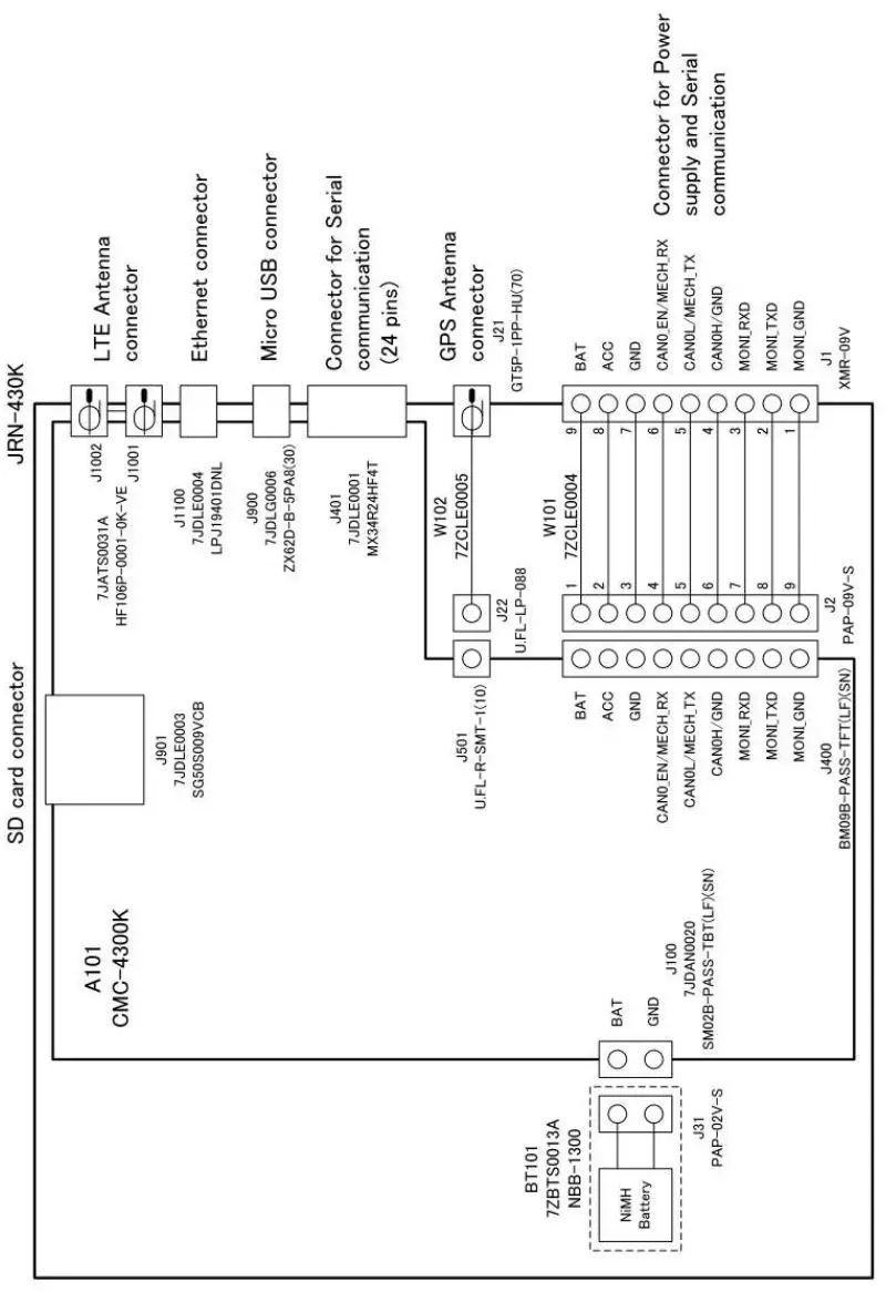
External connector specification
| NO. | Items | Specification performance |
| 1 | Power/Serial connector | MXR connector (JST product) Model: MXR-09V _Cable side connector model: XMP-09V(JST product)_ |
| 2 | Interface connector | (JAE product) Model: MX34R24HF4T |
| 3 | GPS antenna connector | GT5 connector (HIROSE product) Model: GT5P-1 PP-HU(70) |
| 4 | Communication antenna connector | FAKRA connector (Yamaichi Denki product) Model: HF106P-0001 |
| 5 | USB connector | (HIROSE product) Model: ZX62D-B-5PA8(30) |
| 6 | Ethernet connector | (LINK-PP product) Model: LPJ19401DNL |
| 7 | SD Card connector | (JAE product) Model: SG50S009VCB |
Software
JRN-430K application software external I/F specifications is prescribed about the command list and block the structure about software.
Implement the software that customers have created.
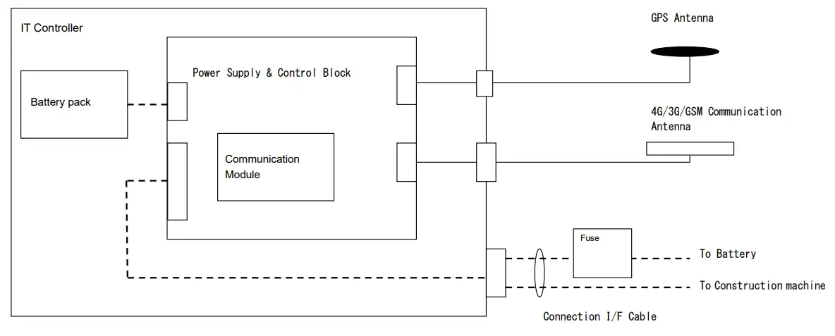
Block Diagram
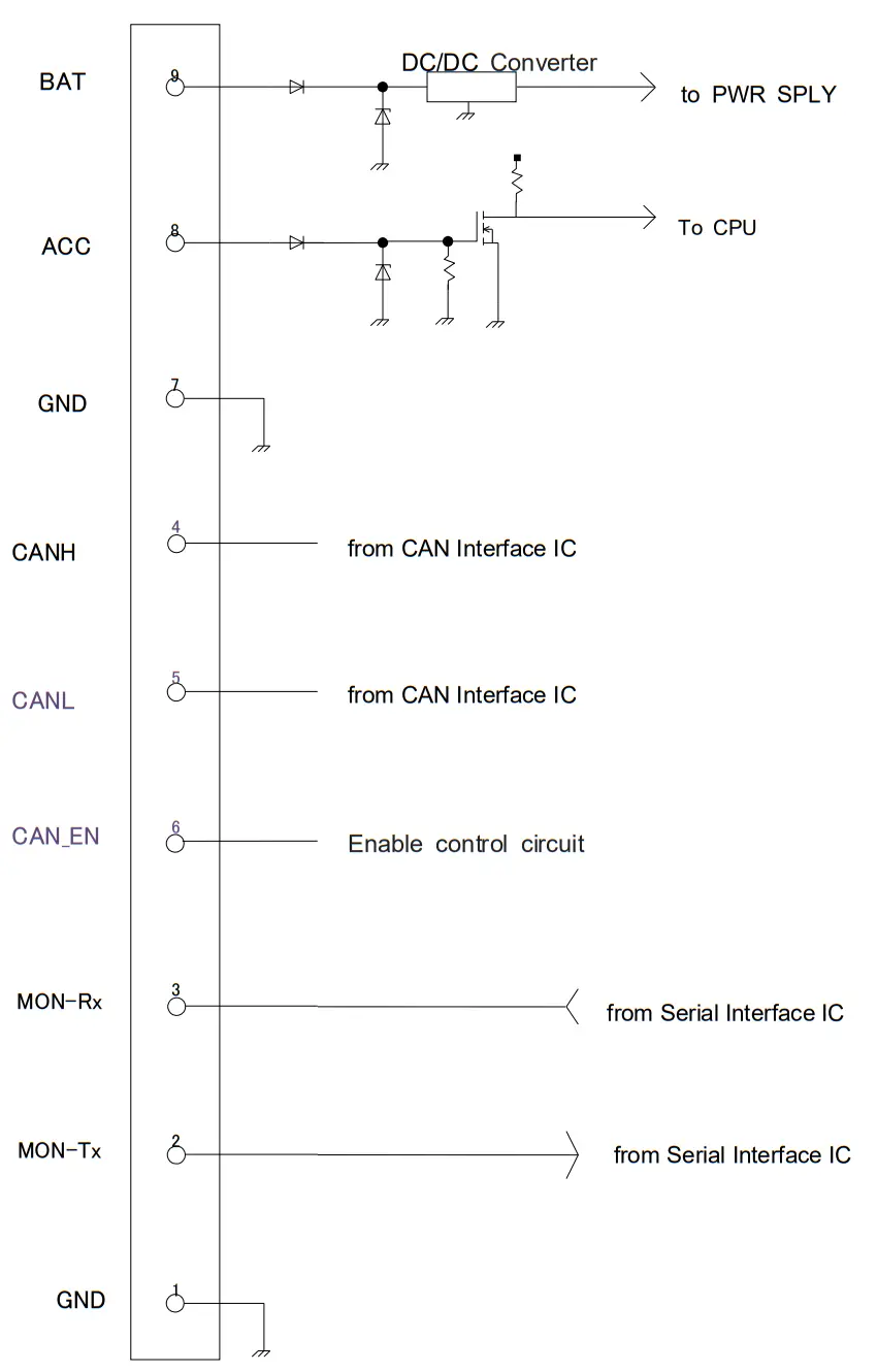
External Interface
External Interface Specification
Pin Assign 
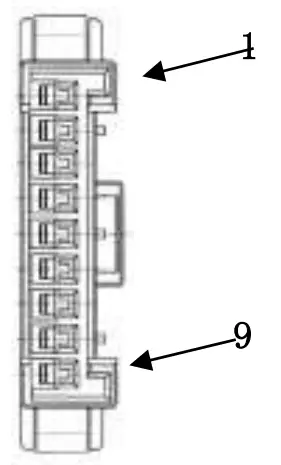
| NO | Terminal name | Remarks |
| 1 | GND | GND |
| 2 | Moni-Tx | Monitor → IT controller |
| 3 | Moni-Rx | IT controller → Monitor |
| 4 | CAN H | CAN Low-Level Voltage I/O |
| 5 | CAN L | CAN High-Level Voltage I/O |
| 6 | CAN_EN | CAN Enable |
| 7 | GND | GND |
| 8 | ACCESS | ACC signal |
| 9 | BAT | Main battery |
Interface Connector
Pin Assign
| NO. | Terminal name | Remarks |
| 1 | CAN1 EN | CAN1 enable signal |
| 2 | CAN1 _H | CAN1 High-Level input/output |
| 3 | CAN1 L | CAN1 Low-Level input/output |
| 4 | CAN1 GND | GND |
| 5 | SOFT RX(0) | Serial output for Linux Kernel |
| 6 | SOFT TX(I) | Serial input for Linux Kernel |
| 7 | SOFT GND | GND |
| 8 | GPIO | GPIO |
| 9 | GPIO GND | GND |
| 10 | GPI1 | GPI1 |
| 11 | GPI1 GND | GND |
| 12 | GPI2 | GPI2 |
| 13 | GPI2 GND | GND |
| 14 | GPO() | GPO() |
| 15 | GOO GND | GND |
| 16 | GP01 | GP01 |
| 17 | GP01 GND | GND |
| 18 | GPO2 | GPO2 |
| 19 | GPO2 GND | GND |
| 20 | GPO3 | GPO3 |
| 21 | GPO3 GND | GND |
| 22 | MECH RX(0) | Serial output for DTE |
| 23 | MECH TX(I) | Serial Input for DTE |
| 24 | GND | GND |
GPS Antenna Connector
Pin Assign
| NO. | Terminal name | Remarks |
| 1 | RF | Receive |
| 2 | GND | GND |
6.4 Communication Antenna Connector Pin Assign
| NO. | Terminal name | Remarks |
| 1 | RF | TX / RX |
| 2 | GND | GND |
USB Connector Pin Assign
| NO. | Terminal name | Remarks |
| 1 | +5V | For power supply + |
| 2 | D- | For data transmission – |
| 3 | D+ | For data transmission + |
| 4 | ID | For identification |
| 5 | GND | For power supply – |
Ethernet Connector Pin Assign
| NO. | Terminal name | Remarks |
| 1 | RD+ | For data reception + |
| 2 | RD- | For data reception – |
| 3 | TD+ | For data transmission + |
| 4 | NC | NC |
| 5 | NC | NC |
| 6 | TD- | For data transmission – |
| 7 | NC | NC |
| 8 | NC | NC |
Equivalent circuit
Outline
Option
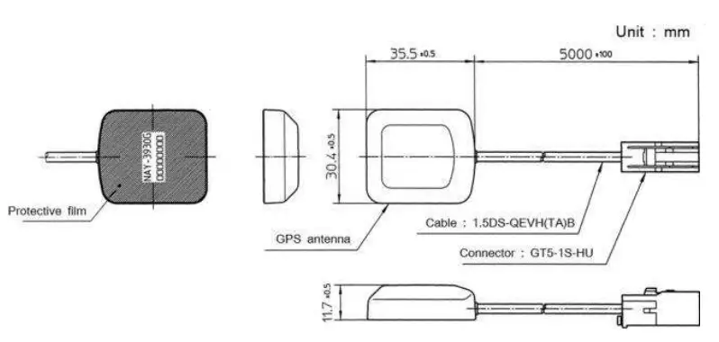
GPS antenna NAY-3930G
Specification
| NO. | Items | Specification performance |
| 1 | Model | NAY-3930G |
| 2 | Power supply voltage | 2.7V to 3.3V |
| 3 | Consumption current | 12mA to 30mA |
| 4 | Cable | 1. 5D Cable and 5M (Black) |
| 5 | Temperature range of operation | -30°C to +85°C |
| 6 | Storage temperature range | -40°C to +100°C |
| 7 | Humidity | 20% to 95% (relativity, however thing without dew condensation) |
| 8 | Received frequency range | 1575. 42 ± 1.023MHz |
| 9 | Polarized wave | Right-handed circular polarization |
| 10 | Profit | 25±6dBi (ascending vertical angle = 90 degrees) |
| 11 | Output impedance | 50 ohms |
| 12 | OUTPUT VSWR | 2.0, or less |
| 13 | Connector | GT5-1P-HU (HIROSE product) |
Outline
Communication antenna
Specification
| No. | Items | Specification performance |
| 1 | Model | 7ABLE0009 (FAKRA) (Nippon Antenna) |
| 2 | Antenna type | Half-wave length dipole antenna |
| 3 | Purpose | For the indoor antenna, double-sided tape attachment |
| 4 | Weight | approximately 70g |
| 5 | Environmental Regulation | Compliant with RoHS and ELV |
| 6 | Frequency | 02 699 803 MI-I z a 814 960 MI-I z C 1427 — 1511 MH z C 1710 — 2170 MHz 5 2496 — 2690 MH z |
| 7 | Nominal impedance | 500 |
| 8 | VSWR | 0 4.0 at the end of the cable. CYDC 2.5 at the end of the cable. 4b 3.0 at the end of the cable. It is measured in free space. |
| 9 | Peak gain | 09 -1.0 dBi at the end of the cable. 0© +1.0 dB at the end of the cable. 0 +1.6 dB at the end of the cable. 4) -2.5 dBi at the end of the cable. It is measured in free space. |
| 10 | Polarization | Vertical |
| 11 | Directivity | Horizontal plane Omni-directional |
| 12 | Input power | Not exceeding 2W |
| 13 | Cable loss (Reference) | 900MHz 1.58dB / 2.5m 2000MHz 2.45dB / 2.5m |
| 14 | Operating temperature range | -30°C to +80°C |
| 15 | Storage temperature range | -40°C to +85°C |
| 16 | Operating humidity limits | 0% to 95% |
| 17 | Connector | FAKRA |
Outline
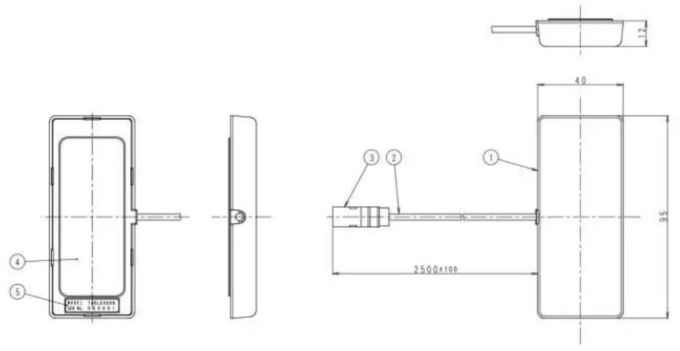
| NO. | Items | Specification performance |
| 1 | Radome material | AES plastic |
| 2 | 1.5D Coaxial cable | 2.5m ± 10cm |
| 3 | TAKARA Rosenberger K | PBT-GF20 other |
| 4 | Double-sided tape | 518TF |
| 5 | Label | Tetoron® film |
Compliance with FCC and IC Rules and Regulations
FCC
This device complies with Part 15 of the FCC Rules. Operation is subject to the following two conditions: (1) This device may not cause harmful interference, and (2) this evice must accept any interference, including interference that may cause undesired operation.
CAUTION:
Any changes or modifications not expressly approved by the party responsible for compliance could void the user’s authority to operate the equipment.
NOTE: This equipment has been tested and found to comply with the limits for a Class B digital device, pursuant to part 15 of the FCC Rules. These limits are designed to provide reasonable protection against harmful interference in a residential installation. This equipment generates, uses and can radiate radio frequency energy and, if not installed and used in accordance with the instructions, may cause harmful interference to radio communications. However, there is no guarantee that interference will not occur in a particular installation. If this equipment does cause harmful interference to radio or television reception, which can be determined by turning the equipment off and on, the user is encouraged to try to correct the interference by one or more of the following measures:
- Reorient or relocate the receiving antenna.
- Increase the separation between the equipment and receiver.
- Connect the equipment into an outlet on a circuit different from that to which the receiver is connected.
- Consult the dealer or an experienced radio/TV technician for help.
This Class B digital apparatus complies with Canadian ICES-003.
Operation is subject to the following two conditions: (1) this device may not cause interference, and (2) this device must accept any interference, including interference that may cause undesired operation of the device.
This radio transmitter (identify the device by certification number, or model number if Category II) has been approved by Industry Canada to operate with the antenna types listed below with the maximum permissible gain and required antenna impedance for each antenna type indicated. Antenna types not included in this list, having a gain greater than the maximum gain indicated for that type, are strictly prohibited for use with this device.
Antenna type/Model name
Maximum Antenna gain :
: Half length dipole antenna/7ABLE0009(FAKRA)
699 – 803MHz -1.0dBi
814 – 960MHz +1.0dBi
1427 – 1511MHz +1.0dBi
1710 – 2170MHz +1.6dBi
2496 – 2690MHz -2.5dBi
Nominal impedance : 50Ω


