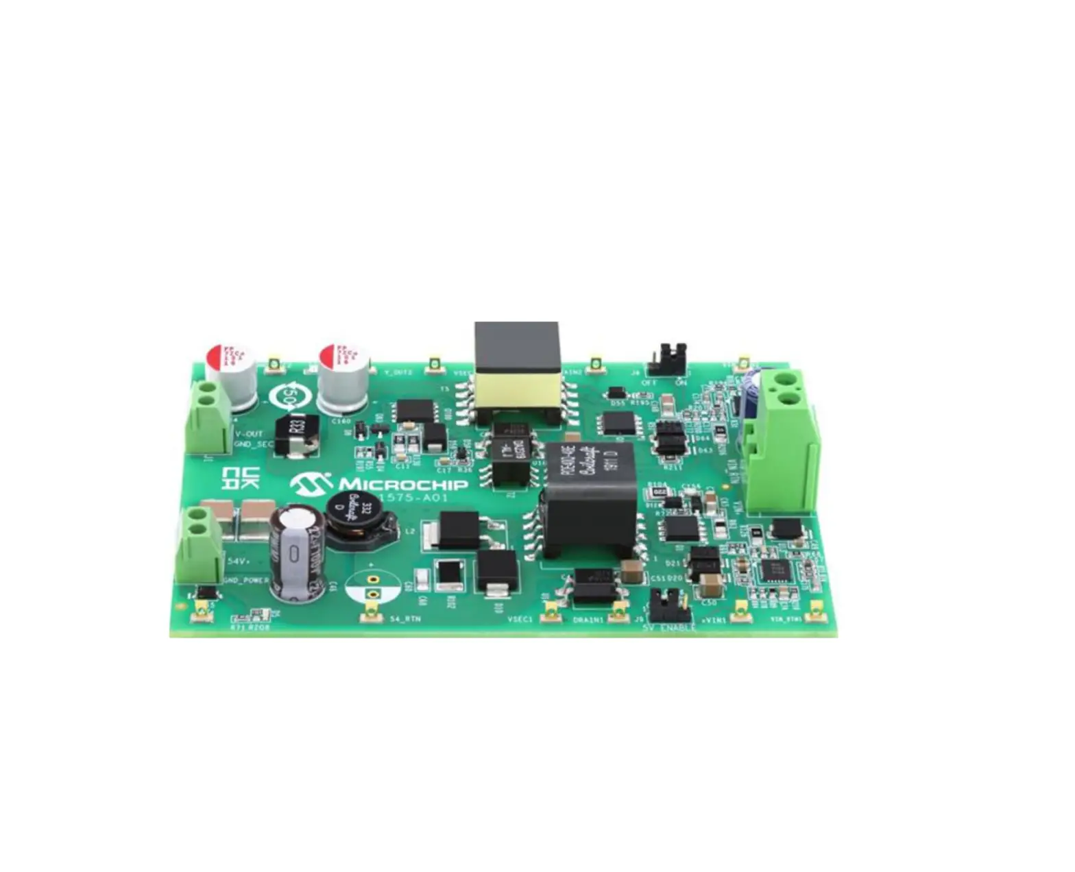
MICROCHIP EV96C70A 55W Dual Output Converter from 36V-54V Input EVB
Introduction
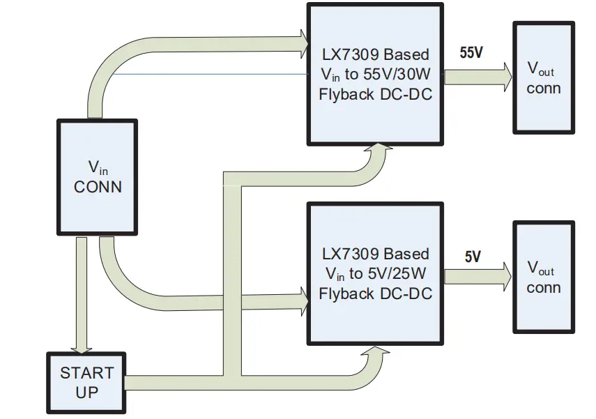
This document provides the description and operating procedures for Microchip’s dual output 55V/30W and 5V/25W board from 36V–54V input EV96C70A. This board type is used for evaluating the performance of Microchip PoE systems and the Microchip PWM controller LX7309, which is an integral part of Microchip PoE PD controllers PD70201 and PD70211.
Microchip’s PD70201 and PD70211 devices are a part of a family of devices that support the IEEE® 802.3af, IEEE 802.3at, and HDBaseT standards PD interface.
The PD interface includes the following family of devices.
Table 1. Microchip Powered Device Products Offerings
| Part | Type | Package | ®IEEE 802.3af | IEEE 802.3at | HDBaseT (PoH) | UPoE |
| PD70100 | Front end | 3 mm × 4 mm 12L DFN | x | — | — | — |
| PD70101 | Front end + PWM | 5 mm × 5 mm 32L QFN | x | — | — | — |
| PD70200 | Front end | 3 mm × 4 mm 12L DFN | x | x | — | — |
| PD70201 | Front end + PWM | 5 mm × 5 mm 32L QFN | x | x | — | — |
| PD70210 | Front end | 4 mm × 5 mm 16L DFN | x | x | x | x |
| PD70210A | Front end | 4 mm × 5 mm 16L DFN | x | x | x | x |
| PD70210AL | Front end | 5 mm × 7 mm 38L QFN | x | x | x | x |
| PD70211 | Front end + PWM | 6 mm × 6 mm 36L QFN | x | x | x | x |
| PD70224 | Ideal diode bridge | 6 mm × 8 mm 40L QFN | x | x | x | x |
Microchip’s EV96C70A evaluation board provides designers with the environment needed for evaluating the performance and implementation of PoE PD applications.
The board uses two PWM LX7309, which are an integral part of Microchip PD controllers PD70201 and PD70211.
This document provides all necessary procedures and instructions to install and operate this board.
Figure 1. EV96C70A Block Diagram
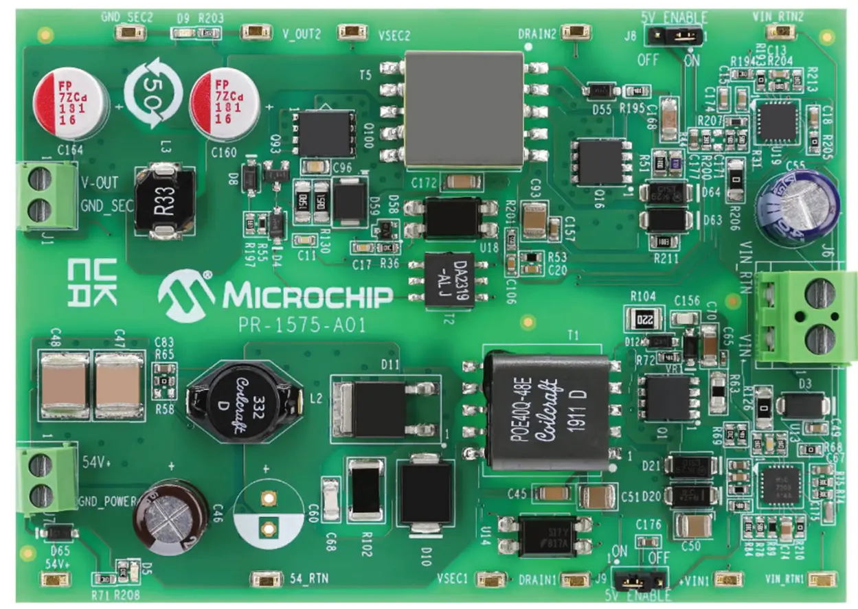
The board can be powered through an input connector J6 by a lab supply or by an output of PoE PD front end. See section 1.3. Electrical Characteristics for the input voltage range. The external load is connected to the evaluation board using the J1 (5V/25W) and J7 (55V/30W) output connectors. The following figure shows the location of input and output connectors.
D5 is the 55V indication LED and D9 is the 5V indication LED. These LEDs indicate the presence of the corresponding outputs.
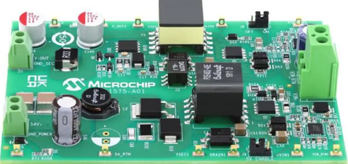
The following figure shows a top view of the evaluation board.
Figure 2. EV96C70A Evaluation Board
Product Overview
This section provides the product overview of the evaluation board.
Evaluation Board Features
- Input DC voltage connector and two output voltage connectors.
- Onboard “output present” LED indicators.
- 36 VDC to 54 VDC input voltage range.
- Evaluation board working temperature: 0 ℃ to 70 ℃.
- RoHS compliant.
Evaluation Board Connectors
The following table lists the evaluation board connectors.
Table 1-1. Connector Details
| # | Connector | Name | Description |
| 1 | J6 | Input connector | Terminal block for connecting DC Input 36V to 54V. |
| 2 | J1 | Output connector | Terminal block for connecting a load to 5V output. |
| 3 | J7 | Output connector | Terminal block for connecting a load to 55V output. |
Input Connector
The following table lists pinout of input connector.
Table 1-2. J1 Connector
| Pin No. | Signal Name | Description |
| Pin 1 | VIN | Positive input voltage 36 VDC to 54 VDC. |
| Pin 2 | VIN_RTN | Return of input voltage. |
- Manufacturer: On Shore Technology.
- Manufacturer part number: ED700/2.
Output Connectors
An external load is connected to the evaluation board using the J1 and J7 output connectors. The following tables list pinouts of the output connector.
The manufacturer and manufacturer part number details of the J1 and J7 output connectors are as follows:
- Manufacturer: Kaifeng Electronic.
- Manufacturer part number: KF350V-02P-14.
Table 1-3. J1 Connector
| Pin No. | Signal Name | Description |
| Pin 1 | VOUT | Positive DC/DC output voltage 5V. |
| Pin 2 | VOUT_RTN | Return of 5V output. |
Table 1-4. J7 Connector
| Pin No. | Signal Name | Description |
| Pin 1 | VOUT | Positive DC/DC output voltage 55V. |
| Pin 2 | VOUT_RTN | Return of 55V output. |
Electrical Characteristics
The following table lists the electrical characteristics of the EV96C70A evaluation board.
Table 1-5. Electrical Characteristics
| Min. | Max. | Unit | |
| Input at J6 | 36 | 57 | V |
| Output voltage at J1 | 4.8 | 5.25 | V |
| Maximum output current at J1 | — | 5 | A |
| Port J1 isolation to input | 1500 | — | VRMS |
| Output voltage at J7 | 54 | 56 | V |
| Maximum output current at J7 | — | 0.55 | A |
| Port J7 isolation to input | 1500 | — | VRMS |
| Port J1 isolation to port J7 | 1500 | — | VRMS |
| Ambient temperature | 0 | 70 | ℃ |
Installation
This section provides information about the installation procedure of the EV96C70A evaluation board.
Note: Ensure that power source of the board is turned OFF before all peripheral devices are connected.
Initial Configuration
Perform the following steps for initial configuration:
- Connect load to the board (using J1 and J7).
- Connect a DC supply to input connector J6.
- Turn ON the DC supply.
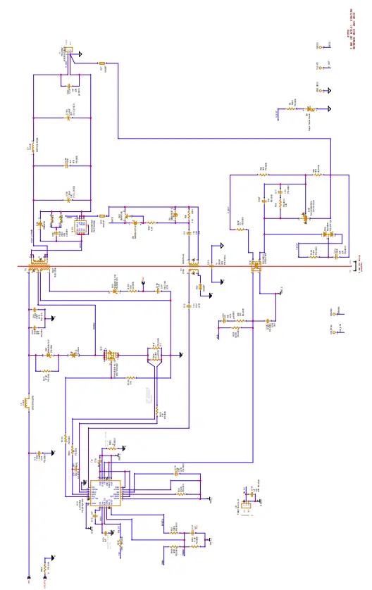
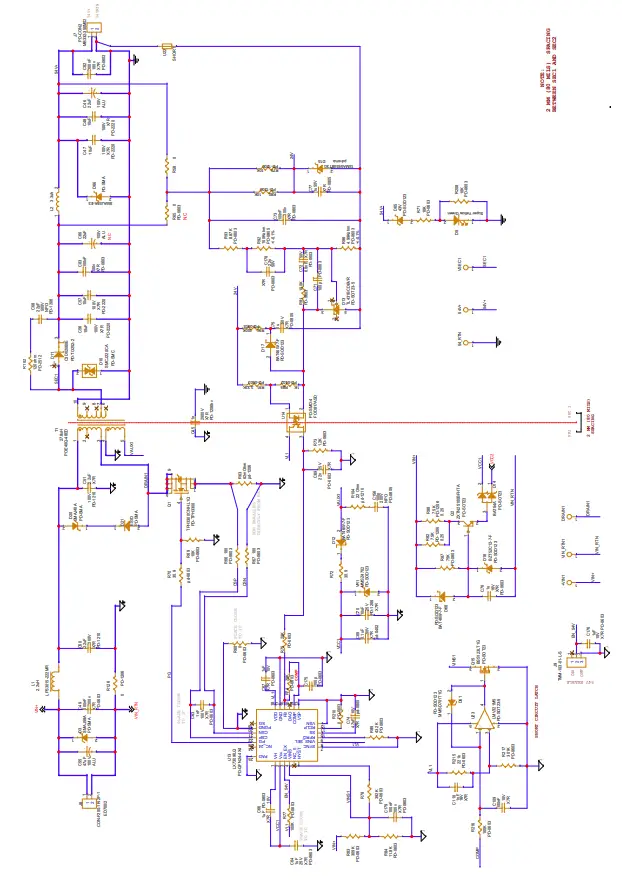
Schematic
Figure 3-1. Schematic
Bill of Materials
The following table lists the bill of materials.
Table 4-1. Bill of Materials
| Item | QTY | Reference | Value | Description | Part Number | Manufacturer |
| 1 | 10 | VSEC1 | HK-2-G-S05 | TEST POINT | HK-2-G-S05 | MAC-8 |
| VIN_RTN1 | HK-2-G-S05 | TEST POINT | HK-2-G-S05 | MAC-8 | ||
| DRAIN1 | HK-2-G-S05 | TEST POINT | HK-2-G-S05 | MAC-8 | ||
| V_OUT2 | HK-2-G-S05 | TEST POINT | HK-2-G-S05 | MAC-8 | ||
| VSEC2 | HK-2-G-S05 | TEST POINT | HK-2-G-S05 | MAC-8 | ||
| VIN_RTN2 | HK-2-G-S05 | TEST POINT | HK-2-G-S05 | MAC-8 | ||
| GND_SEC2 | HK-2-G-S05 | TEST POINT | HK-2-G-S05 | MAC-8 | ||
| DRAIN2 | HK-2-G-S05 | TEST POINT | HK-2-G-S05 | MAC-8 | ||
| 54_RTN | HK-2-G-S05 | TEST POINT | HK-2-G-S05 | MAC-8 | ||
| 54V+ | HK-2-G-S05 | TEST POINT | HK-2-G-S05 | MAC-8 | ||
| 2 | 7 | C3 | 100 nF | Capacitor, X7R, 100 nF, 100V, 10% 0603 | 06031C104KAT2A | AVX |
| C49 | 100 nF | Capacitor, X7R, 100 nF,100V, 10% 0603 | 06031C104KAT2A | AVX | ||
| C73 | 100 nF | Capacitor, X7R, 100 nF,100V, 10% 0603 | 06031C104KAT2A | AVX | ||
| C82 | 100 nF | Capacitor, X7R, 100 nF, 100V, 10% 0603 | 06031C104KAT2A | AVX | ||
| C83 | 100 nF | Capacitor, X7R, 100 nF,100V, 10% 0603 | 06031C104KAT2A | AVX | ||
| C157 | 100nF | Capacitor, X7R, 100nF,100v, 10% 0603 | 06031C104KAT2A | AVX | ||
| C179 | 100 nF | Capacitor, X7R, 100 nF,100V, 10% 0603 | 06031C104KAT2A | AVX | ||
| 3 | 3 | C11 | 10n | CAP CRM 10 nF, 50V, 10%X7R 0603 SMT | MCH185CN103KK | Rohm |
| C12 | 10n | CAP CRM 10 nF, 50V, 10%X7R 0603 SMT | MCH185CN103KK | Rohm | ||
| C17 | 10n | CAP CRM 10 nF 50V 10%X7R 0603 SMT | MCH185CN103KK | Rohm | ||
| 4 | 1 | C13 | 36p | CAP CRM 36 pF, 50V, 5% C0G 0603 SMT | 06035A360JAT2A | AVX |
| 5 | 4 | C15 | 1 μF | Capacitor, X7R, 1 μF, 25V, 10% 0603 | GRM188R71E105KA12D | Murata |
| C18 | 1 μF | Capacitor, X7R, 1μF, 25V, 10% 0603 | GRM188R71E105KA12D | Murata | ||
| C171 | 1 μF | Capacitor, X7R, 1uF, 25V, 10% 0603 | GRM188R71E105KA12D | Murata | ||
| C174 | 1 μF | Capacitor, X7R, 1 μF, 25V, 10% 0603 | GRM188R71E105KA12D | Murata | ||
| 6 | 1 | C19 | 100 pF | CAP COG 100 pF, 50V, 5% 0603 | C1608C0G1H101J | TDK |
| 7 | 1 | C20 | 47n | CAP CRM 47n, 50V, 0603 | CL10B473KB8NNNC | Samsung |
| 8 | 1 | C45 | 1n | CAP CRM 1 nF/2000V, 10% X7R 1206 | C1206C102KGRAC | Kemet |
| 9 | 2 | C46 | 22 μF | CAP ALU 22 μF, 100V, 20%8X11.5 105C | EEUFC2A220 | Panasonic |
| C60 | 22 μF | CAP ALU 22 μF, 100V, 20%8X11.5 105C | EEUFC2A220 | Panasonic |
| 10 | 4 | C47 | 10 μF | CAP CER 10 μF, 100V, 20% X7R 2220 | 22201C106MAT2A | AVX |
| C48 | 10 μF | CAP CER 10 μF, 100V, 20% X7R 2220 | 22201C106MAT2A | AVX | ||
| C56 | 10 μF | CAP CER 10 μF, 100V, 20% X7R 2220 | 22201C106MAT2A | AVX | ||
| C57 | 10 μF | CAP CER 10 μF, 100V, 20% X7R 2220 | 22201C106MAT2A | AVX | ||
| 11 | 2 | C50 | 2.2 μF | CAP CRM 2.2 μF, 100V, X7R 1210 | C1210C225K1RACTU | Kemet |
| C51 | 2.2 μF | CAP CRM 2.2 μF, 100V, X7R 1210 | C1210C225K1RACTU | Kemet | ||
| 12 | 1 | C55 | 47 μF | CAP ALU 47 μF, 100V, 20% 105C | 100PX47MEFCT78X11.5 | Rubicon |
| 13 | 1 | C63 | 1 nF | Cap 1 nF 100V 10% X7R 0603 SMT | CL10B102KC8NNNC | Samsung |
| 14 | 1 | C64 | 1 μF | Cap 1nF 100V 10% X7R 0603 SMT | CL10B105KA8NNNC | Samsung |
| 15 | 1 | C65 | 0.1 μF | CAP CRM 0.1 μF, 50V, X7R 0603 | UMK105B7104KV-FR | Taiyo Yuden |
| 16 | 4 | C66 | 1 μF | Capacitor, X7R 1 μF 10V, 10% 0603 | GRM188R71A105KA61D | Murata |
| C67 | 1 μF | Capacitor, X7R, 1 μF, 10V, 10% 0603 | GRM188R71A105KA61D | Murata | ||
| C176 | 1 μF | Capacitor, X7R, 1μF, 10V, 10% 0603 | GRM188R71A105KA61D | Murata | ||
| C177 | 1 μF | Capacitor, X7R, 1 μF, 10V, 10% 0603 | GRM188R71A105KA61D | Murata | ||
| 17 | 1 | C68 | 22 pF | CAP CRM 22 pF, 500V, 10% NPO 1206 SMT | VJ1206A220JXEAT | Vishay |
| 18 | 1 | C69 | 22n | CAP CRM 22 nF, 25V, 10%X7R 0603 SMT | VJ0603Y223KXXCW1BC | Vishay |
| 19 | 2 | C70 | 10 μF | Capacitor, X7R, 10 μF, 25V, 10% 1206 | C1206C106K3RACTU | Kemet |
| C168 | 10 μF | Capacitor, X7R, 10 μF, 25V, 10% 1206 | C1206C106K3RACTU | Kemet | ||
| 20 | 2 | C71 | 100p | CAP CRM 100 pF 100V 5% NPO 0603 SMT | VJ0603A101JXBT | Vishay |
| C175 | 100p | CAP CRM 100pF 100V 5%NPO 0603 SMT | VJ0603A101JXBT | Vishay | ||
| 21 | 1 | C72 | 6.8 nF | CAP CER 6.8 nF, 50V, 10% X7R 0603 SMT | 06035C682KAT2A | AVX |
| 22 | 2 | C74 | 4.7 μF | CAP CRM 4.7 μF, 10V, 10%X7R 0805 SMT | 0805ZC475KAT2A | AVX |
| C165 | 4.7 μF | CAP CRM 4.7 μF, 10V, 10%X7R 0805 SMT | 0805ZC475KAT2A | AVX | ||
| 23 | 1 | C75 | 1μ | CAP CRM 1 μF 50V 10% X7R 0805 SMT | UMK212B7105KG-T | Taiyo Yuden |
| 24 | 1 | C76 | 1μ | CAP CRM 1 μF, 16V, 10% 0805 X7R SMT | CL10B105KO8NNNC | Samsung |
| 25 | 1 | C77 | 1μ | CAP CRM 1 μF, 50V, 10% X7R 0805 SMT | GRM21BR71H105KA12L | Murata |
| 26 | 1 | C93 | 2.2 μF | CAP CRM 2.2 μF 100V X7R 1210 | C3225X7R2A225K | TDK |
| 27 | 1 | C96 | 820 pF | CAP CRM 820p, 200V, X7R 0805 | 08052C821KAT2A | AVX |
| 28 | 1 | C106 | 3.3 nF | CAP CRM 3.3 nF, 16V, X7R 0603 | C1608X7R1C332K | TDK |
| 29 | 2 | C109 | 100 nF | CAP CRM 100 nF, 10V, X7R 0603 | GRM188R71H104KA01 | Murata |
| C173 | 100 nF | CAP CRM 100 nF, 10V, X7R 0603 | GRM188R71H104KA01 | Murata | ||
| 30 | 1 | C110 | 1 nF | CAP CRM 1 nF, 16V, X7R 0603 | CL10B102KA8NNNC | Samsung |
| 31 | 1 | C156 | 100p | CAP CRM 100 pF, 200V, NPO 0805 | 08052A101KAT2A | AVX |
| 32 | 2 | C160 | 180 μF | CAP Polymer Alum. 180 μF, 16V, 20% | RL81C181MDN1KX | Nichicon |
| 33 | 1 | C163 | 100n | CAP CRM 100 nF 16V 10%X7R 0603 SMT | VJ0603Y104KXJCW1BC | Vishay |
| 34 | 1 | C170 | 10n | CAP CRM 10 nF, 50V, 10%X7R 0603 SMT | C1608X7R1H103K080AA | TDK |
| 35 | 1 | C172 | 1n | CAP CRM 1 nF/2000V, 10%++X7R 1206 SMT | 1206B102K202CT | Walsin |
| 36 | 1 | C178 | 2.2n | CAP CRM 2.2 nF, 50V, 10%X7R 0603 SMT | C0603C222K5RAC | Kemet |
| 37 | 1 | D3 | SMAJ58A | DIO TVS 58V, 40A, SRG400WPK SMA SMT | SMAJ58A | Vishay |
| 38 | 2 | D4 | MBR0540T1G | DIO SCHOTTKY 40V, 500 mA, SOD123 REC. SMT | MBR0540T1G | ON Semi |
| D8 | MBR0540T1G | DIO SCHOTTKY 40V, 500 mA, SOD123 REC. SMT | MBR0540T1G | ON Semi | ||
| 39 | 2 | D5 | LED | LED SuperYelGrn 100-130o 0603 SMD | 19-21-SYGCS530E3TR8 | Ever light |
| D9 | LED | LED SuperYelGrn 100-130o 0603 SMD | 19-21-SYGCS530E3TR8 | Ever light | ||
| 40 | 1 | D10 | SMCJ220CA | TVS DIODE Bidirectional 220V WM 356VC SMC | SMCJ220CA | Littelfuse |
| 41 | 1 | D11 | C3D02060E | Diode Schottky Zero Recovery 600V DPAK | C3D02060E | Cree Inc |
| 42 | 3 | D12 | BAT46W-7-F | Diode Schottky 100V, 150 mA, SOD123F | BAT46W-7-F | Diodes Inc. |
| D17 | BAT46W-7-F | Diode Schottky 100V, 150 mA, SOD123F | BAT46W-7-F | Diodes Inc. | ||
| D68 | BAT46W-7-F | Diode Schottky 100V, 150 mA , SOD123F | BAT46W-7-F | Diodes Inc. | ||
| 43 | 1 | D13 | TL431BCDBVR | IC AdjPrec Shunt Reg 2.5V, 0.5%, SOT23-5 | TL431BCDBVR | TI |
| 44 | 1 | D14 | BAT54A | DIO Schottky 30V 200 mASOT23 | BAT54A | Philips |
| 45 | 1 | D15 | 1SMA5934BT3G | DIODE ZENER 24V, 1.5W, SMA SMT | 1SMA5934BT3G | ON Semi |
| 46 | 1 | D16 | BZT52C12-7-F | DIO ZENER 12V, 500 mW, SOD123 SMT | BZT52C12-7-F | Diodes Inc. |
| 47 | 1 | D20 | SMAJ40A | DIODE TVS 40V, 400W, 5 μA, 6.2A | SMAJ40A | Bourns |
| 48 | 2 | D21 | ES1D | DIODE ULTRA FAST 200V, 1A, DO-214AC | ES1D | Fairchild |
| D64 | ES1D | DIODE ULTRA FAST 200V, 1A, DO-214AC SMT | ES1D | Fairchild | ||
| 49 | 2 | D55 | MMSD701T1G | DIODE SCHOTTKY 70V 0.2A, 225W, SOD123 | MMSD701T1G | ON Semi |
| D61 | MMSD701T1G | DIODE SCHOTTKY 70V 0.2A, 225W, SOD123 | MMSD701T1G | ON Semi | ||
| 50 | 1 | D58 | BAV99W | Diode, Dual Switching BAV99W SOT323 | BAV99W | NXP |
| 51 | 1 | D59 | SMBJ24A | TVS DIODE 24V 38.9V SMBJ | SMBJ24A | BRIGHTKING |
| 52 | 1 | D62 | TL431CDBVRE4 | IC Prog Shunt Ref 2.5V, 2% SOT23-5 SMT | TL431CDBVRE4 | TI |
| 53 | 1 | D63 | SMAJ58A-13-F | DIO TVS 58V 40A SRG400WPK SMA SMT | SMAJ58A-13-F | Diodes Inc. |
| 54 | 1 | D65 | DDZ9717-7 | Diode, Zener, 500 mW, 43V, 5% SOD123 | DDZ9717-7 | Diodes Inc. |
| 55 | 1 | D66 | SMAJ58A-E3 | DIO TVS 58V, 40A, SRG400WPK SMA SMT | SMAJ58A-E3 | Vishay |
| 56 | 2 | J1 | PD-CON2 | Terminal block 2 Pole interlocking 3.5 mm pitch | MB332-350M02 | DECA |
| J7 | PD-CON2 | Terminal block 2 Pole interlocking 3.5mm pitch | MB332-350M02 | DECA | ||
| 57 | 1 | J6 | ED700/2 | TERMINAL BLOCK 5MM 2POS PCB | ED700/2 | On Shore Tech |
| 58 | 2 | J8 | TMM-103-01-L-S | Con Male PIN Header 3P 2 mm Vertical SR TH | TMM-103-01-L-S | Samtec |
| J9 | TMM-103-01-L-S | Con Male PIN Header 3P 2 mm Vertical SR TH | TMM-103-01-L-S | Samtec | ||
| 59 | 1 | L1 | 2.2 μH | Power Inductors 2.2 μHy, 1.5A, 110m SMT | LPS3015-222MR | Coilcraft |
| 60 | 1 | L2 | 3.3 μH | Inductor 3.3 μH, 0.015R, 6.4A, SMT | L0-3316-3R3-RM | ICE Comp |
| 61 | 1 | L3 | 0.33 μH | Power Inductor 0.33 μH, 20A , Shilded SMT | SRP7030-R33M | Bourns |
| 62 | 1 | L4 | 2.2 μH | Power Inductors 2.2 μHy, 1.5A , 110mΩ | LPS3015-222ML | Coilcraft |
| 63 | 2 | Q1 | TPH3300CNH,L1Q | MOSFET N-CH 150V, 18A 8-SOP | TPH3300CNH,L1Q | Toshiba |
| Q16 | TPH3300CNH,L1Q | MOSFET N-CH 150V, 18A 8-SOP | TPH3300CNH,L1Q | Toshiba | ||
| 64 | 1 | Q2 | ZXTN25100BFHTA | TRANSISTOR NPN 100V, 3A, SOT23-3 SMT | ZXTN25100BFHTA | Diodes Inc. |
| 65 | 1 | Q15 | BSS123LT1G | FET NCH 100V 0.15A 6RLogic Level SOT23 | BSS123LT1G | ON Semi |
| 66 | 1 | Q93 | FMMT549 | TRN PNP -30V -1A SOT23 | FMMT549 | Fairchild |
| 67 | 1 | Q100 | BSC0902NSI | MOSFET N-Ch 30V, 100A, TDSON-8 | BSC0902NSI | Infineon |
| 68 | 2 | R31 | 392K | RES 392K, 0.1W, 1%, 0603 SMT MTL FLM | RC0603FR-07392KL | Yageo |
| R78 | 392K | RES 392K, 0.1W 1%, 0603 SMT MTL FLM | RC0603FR-07392KL | Yageo | ||
| 69 | 1 | R34 | 43.2K | RES 43.2K, 100 mW, 0603SMT 1% | ERJ3EKF4322V | Panasonic |
| 70 | 1 | R36 | 10K | RES 10K 62.5 mW 1% 0603 SMT MTL FLM | RC0603FRF-0710KL | Yageo |
| 71 | 1 | R44 | 0.082 | RES 0.082Ω 1/4W 1% 0805 SMT | UR732ATTD82L0F | KOA |
| 72 | 1 | R51 | 1 | RES 1R 125mW 1% 0805 SMT MTL FLM | RC0805FR-071R | Yageo |
| 73 | 2 | R52 | 56K | Resistor, SMT 56K, 1%, 1/10W 0603 | CRCW060356K0FKEA | Vishay |
| R54 | 56K | Resistor, SMT 56K, 1%, 1/10W 0603 | CRCW060356K0FKEA | Vishay | ||
| 74 | 1 | R53 | 332 | RES 332R 62.5 mW 1% 0603 SMT MTL FLM | RC0603FRF07332R | Yageo |
| 75 | 1 | R55 | 5.1K | RES TCK FLM 5.1K, 62.5 mW, 1% 0603 SMT | CRCW06035K1FKEA | Vishay |
| 76 | 4 | R58 | 0 | RES TCK FLM 0R 62.5 mW, 5% 0603 SMT | ERJ3GEY0R00V | Panasonic |
| R65 | 0 | RES TCK FLM 0R 62.5 mW, 5% 0603 SMT | ERJ3GEY0R00V | Panasonic | ||
| R68 | 0 | RES TCK FLM 0R 62.5mW, 5% 0603 SMT | ERJ3GEY0R00V | Panasonic | ||
| R210 | 0 | RES TCK FLM 0R 62.5 mW, 5% 0603 SMT | ERJ3GEY0R00V | Panasonic | ||
| 77 | 1 | R63 | 62 mΩ | RES .062Ω, 1/2W, 1%, 1206 SMT | ERJ8BWFR062V | Panasonic |
| 78 | 4 | R66 | 100 | RES TCK FLM 100R 62.5mW 1% 0603 SMT | RC0603FR-07100RL | Yageo |
| R67 | 100 | RES TCK FLM 100R, 62.5 mW, 1% 0603 SMT | RC0603FR-07100RL | Yageo | ||
| R204 | 100 | RES TCK FLM 100R, 62.5 mW, 1% 0603 SMT | RC0603FR-07100RL | Yageo | ||
| R213 | 100 | RES TCK FLM 100R 62.5 mW 1% 0603 SMT | RC0603FR-07100RL | Yageo | ||
| 79 | 1 | R69 | 10K | RES 10K 62.5 mW 1% 0603 SMT MTL FLM | RC1608F1002CS | Samsung |
| 80 | 2 | R70 | 30.9 | Resistor, 30.9R, 1%, 1/10W, 0603 | CRCW060330R9FKEA | Vishay |
| R72 | 30.9 | Resistor, 30.9R, 1%, 1/10W, 0603 | CRCW060330R9FKEA | Vishay | ||
| 81 | 2 | R71 | 10K | RES 10K, 62.5mW, 1% 0603 SMT MTL FLM | CR16-1002FL | ASJ |
| R208 | 10K | RES 10K, 62.5 mW, 1% 0603 SMT MTL FLM | CR16-1002FL | ASJ | ||
| 82 | 1 | R73 | 1.2K | Resistor, SMT 1.2K, 5% 1/10W 0603 | CRCW06031K20JNEA | Vishay |
| 83 | 2 | R74 | 20K | RES 20K, 62.5 mW, 1% 0603 SMT MTL FLM | ERJ3EKF2002V | Panasonic |
| R75 | 20K | RES 20K 62.5mW 1% 0603 SMT MTL FLM | ERJ3EKF2002V | Panasonic | ||
| 84 | 4 | R77 | 100K | RES 100K 62.5 mW 1% 0603 SMT MTL FLM | MCR03EZPFX1003 | Rohm |
| R81 | 100K | RES 100K, 62. 5 mW, 1% 0603 SMT MTL FLM | MCR03EZPFX1003 | Rohm | ||
| R94 | 100K | RES 100K 62.5 mW, 1% 0603 SMT MTL FLM | MCR03EZPFX1003 | Rohm | ||
| R207 | 100K | RES 100K 62.5 mW, 1% 0603 SMT MTL FLM | MCR03EZPFX1003 | Rohm | ||
| 85 | 2 | R79 | 10K | RES 10K, 250 mW, 1% 1206 SMT MTL FLM | RC1206FR-0710KL | Yageo |
| R80 | 10K | RES 10K 250 mW, 1% 1206 SMT MTL FLM | RC1206FR-0710KL | Yageo | ||
| 86 | 2 | R82 | 7.5K | RES 7.5K 250 mW, 1% 1206 SMT MTL FLM | CR1206-FX-7501ELF | Bourns |
| R88 | 7.5K | RES 7.5K 250 mW, 1% 1206 SMT MTL FLM | CR1206-FX-7501ELF | Bourns | ||
| 87 | 2 | R83 | 309K | RES 309K 62.5 mW, 1% 0603 SMT MTL FLM | RC0603FR-07309KL | Yageo |
| R199 | 309K | RES 309K 62.5 mW, 1% 0603 SMT MTL FLM | RC0603FR-07309KL | Yageo | ||
| 88 | 2 | R84 | 11.8K | RES 11.8K 0.1W 1% 0603 SMT MTL FLM | RC1608F1182CS | Samsung |
| R200 | 11.8K | RES 11.8K, 0.1W, 1% 0603 SMT MTL FLM | RC1608F1182CS | Samsung | ||
| 89 | 1 | R85 | 1K | RES TCK FLM 1K, 1%, 62.5 mW, 0402 SMT, 100 PPM | CR0402-FX-1001GLF | Bourns |
| 115 | 1 | U13 | LX7309ILQ | Synchronous Flyback DC/DC Controller | LX7309ILQ | Microchip |
| 116 | 1 | U19 | LX7309ILQ | Synchronous Flyback DC/DC Controller | LX7309ILQ | Microchip |
| 117 | 1 | U14 | FOD817ASD | OPTOISOLATOR 5 KV TRANSISTOR 4 SMD | FOD817ASD | Fairchild |
| 118 | 1 | U18 | FOD817ASD | OPTOISOLATOR 5 KV TRANSISTOR 4 SMD | FOD817ASD | Fairchild |
| 119 | 1 | U23 | LMV321M5 | IC OPAMP SINGLE RAIL-RAIL SOT23-5 | LMV321M5 | National |
| 120 | 1 | VR1 | MMSZ4702 | DIODE ZENER 15V 500MW SOD123 | MMSZ4702 | Fairchild |
Note: Third-party components can be replaced by approved equivalents. N.C = not installed (optional).
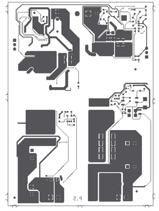
Board Layout
This section describes the layout of the evaluation board. This is a four-layer board with 2 Oz copper. The following figures show the silk of the board for tracking devices placements.
Figure 5-1. Top Silk
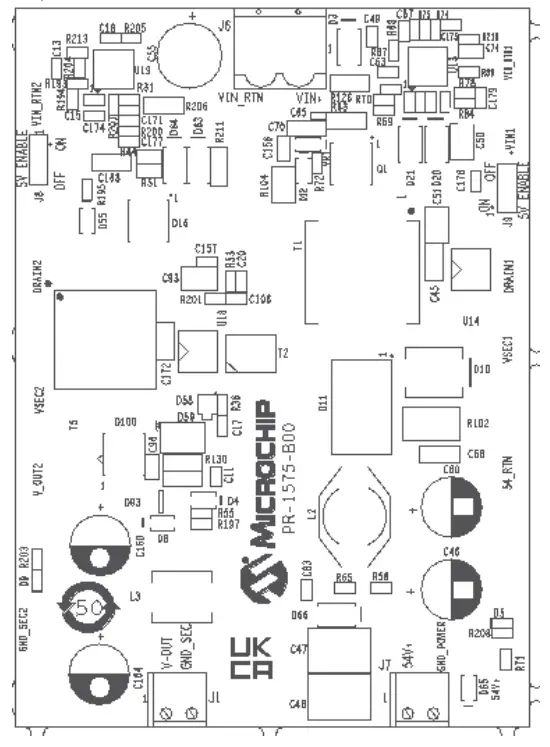
Figure 5-2. Bottom Silk
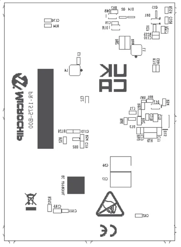
Figure 5-3. Top Copper
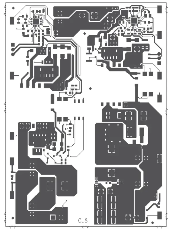
Figure 5-4. Bottom Copper
Ordering Information
The following table lists the evaluation board ordering information.
Table 6-1. Evaluation Board Ordering Information
| Ordering Number | Description |
| EV96C70A | 55W Dual Output Isolated Fullback Converter from 36V to 54V input. |
Revision History
| Revision | Date | Description |
| B | 03/2022 | Following is the summary of changes made in this revision:
|
| A | 01/2022 | Initial revision. |
The Microchip Website
Microchip provides online support via our website at www.microchip.com/. This website is used to make files and information easily available to customers. Some of the content available includes:
- Product Support – Data sheets and errata, application notes and sample programs, design resources, user’s guides and hardware support documents, latest software releases and archived software
- General Technical Support – Frequently Asked Questions (FAQs), technical support requests, online discussion groups, Microchip design partner program member listing
- Business of Microchip – Product selector and ordering guides, latest Microchip press releases, listing of seminars and events, listings of Microchip sales offices, distributors and factory representatives
Product Change Notification Service
Microchip’s product change notification service helps keep customers current on Microchip products. Subscribers will receive email notification whenever there are changes, updates, revisions or errata related to a specified product family or development tool of interest.
To register, go to www.microchip.com/pcn and follow the registration instructions.
Customer Support
Users of Microchip products can receive assistance through several channels:
- Distributor or Representative
- Local Sales Office
- Embedded Solutions Engineer (ESE)
- Technical Support
Customers should contact their distributor, representative or ESE for support. Local sales offices are also available to help customers. A listing of sales offices and locations is included in this document.
Technical support is available through the website at: www.microchip.com/support
Microchip Devices Code Protection Feature
Note the following details of the code protection feature on Microchip products:
- Microchip products meet the specifications contained in their particular Microchip Data Sheet.
- Microchip believes that its family of products is secure when used in the intended manner, within operating specifications, and under normal conditions.
- Microchip values and aggressively protects its intellectual property rights. Attempts to breach the code protection features of Microchip product is strictly prohibited and may violate the Digital Millennium Copyright Act.
- Neither Microchip nor any other semiconductor manufacturer can guarantee the security of its code. Code protection does not mean that we are guaranteeing the product is “unbreakable”. Code protection is constantly evolving. Microchip is committed to continuously improving the code protection features of our products.
Legal Notice
This publication and the information herein may be used only with Microchip products, including to design, test, and integrate Microchip products with your application. Use of this information in any other manner violates these terms. Information regarding device applications is provided only for your convenience and may be superseded by updates. It is your responsibility to ensure that your application meets with your specifications. Contact your local Microchip sales office for additional support or, obtain additional support t at www.microchip.com/en-us/support/ design-help/client-support-services.
THIS INFORMATION IS PROVIDED BY MICROCHIP “AS IS”. MICROCHIP MAKES NO REPRESENTATIONS OR WARRANTIES OF ANY KIND WHETHER EXPRESS OR IMPLIED, WRITTEN OR ORAL, STATUTORY OR OTHERWISE, RELATED TO THE INFORMATION INCLUDING BUT NOT LIMITED TO ANY IMPLIED WARRANTIES OF NON-INFRINGEMENT, MERCHANTABILITY, AND FITNESS FOR A PARTICULAR PURPOSE, OR WARRANTIES RELATED TO ITS CONDITION, QUALITY, OR PERFORMANCE.
IN NO EVENT WILL MICROCHIP BE LIABLE FOR ANY INDIRECT, SPECIAL, PUNITIVE, INCIDENTAL, OR CONSEQUENTIAL LOSS, DAMAGE, COST, OR EXPENSE OF ANY KIND WHATSOEVER RELATED TO THE INFORMATION OR ITS USE, HOWEVER CAUSED, EVEN IF MICROCHIP HAS BEEN ADVISED OF THE POSSIBILITY OR THE DAMAGES ARE FORESEEABLE. TO THE FULLEST EXTENT ALLOWED BY LAW, MICROCHIP’S TOTAL LIABILITY ON ALL CLAIMS IN ANY WAY RELATED TO THE INFORMATION OR ITS USE WILL NOT EXCEED THE AMOUNT OF FEES, IF ANY, THAT YOU HAVE PAID DIRECTLY TO MICROCHIP FOR THE INFORMATION.
Use of Microchip devices in life support and/or safety applications is entirely at the buyer’s risk, and the buyer agrees to defend, indemnify and hold harmless Microchip from any and all damages, claims, suits, or expenses resulting from such use. No licenses are conveyed, implicitly or otherwise, under any Microchip intellectual property rights unless otherwise stated.
Quality Management System
For information regarding Microchip’s Quality Management Systems, please visit www.microchip.com/quality.
Worldwide Sales and Service
AMERICAS
Corporate Office
2355 West Chandler Blvd.
Chandler, AZ 85224-6199
Tel: 480-792-7200
Fax: 480-792-7277
Technical Support:
www.microchip.com/support
Web Address:
www.microchip.com
Atlanta
Duluth, GA
Tel: 678-957-9614
Fax: 678-957-1455
Austin, TX
Tel: 512-257-3370
Boston
Westborough, MA
Tel: 774-760-0087
Fax: 774-760-0088
Chicago
Itasca, IL
Tel: 630-285-0071
Fax: 630-285-0075
Dallas
Addison, TX
Tel: 972-818-7423
Fax: 972-818-2924
Detroit
Novi, MI
Tel: 248-848-4000
Houston, TX
Tel: 281-894-5983
Indianapolis
Noblesville, IN
Tel: 317-773-8323
Fax: 317-773-5453
Tel: 317-536-2380
Los Angeles
Mission Viejo, CA
Tel: 949-462-9523
Fax: 949-462-9608
Tel: 951-273-7800
Raleigh, NC
Tel: 919-844-7510
New York, NY
Tel: 631-435-6000
San Jose, CA
Tel: 408-735-9110
Tel: 408-436-4270
Canada – Toronto
Tel: 905-695-1980
Fax: 905-695-2078

References
 青娱乐极品盛宴_午夜羞羞影院男女爽爽爽_白丝小舞被啪到娇喘不停_狠狠综合久久久综合网大蛇
 Empowering Innovation | Microchip Technology
-
Empowering Innovation | Microchip Technology
-
Support | Microchip Technology
-
Product Change Notification | Microchip Technology
-
Quality | Microchip Technology
-
Microchip Lightning Support
-
Client Support Services | Microchip Technology


 Dual Port Car Charger User Guide")


