![]() WP10 Washer Tank
WP10 Washer Tank
Instruction Manual
Preserve this manual as a reference for future needs.
Nothing from this publication may be copied, translated, reproduced, and/or published by means of printing, photocopying, or by any other means without the prior written permission of TKH Security. TKH Security reserves the right to modify the specifications stated in this manual.
Brand names
Any brand names mentioned in this manual are registered trademarks of their respective owners.
Liability
TKH Security accepts no liability for claims from third parties arising from improper use other than that stated in this manual.
Although considerable care has been taken to ensure a correct and suitably comprehensive description of all relevant product components, this manual may nonetheless contain errors and inaccuracies. We invite you to offer your suggestions and comments by email via [email protected] Your feedback will help us to further improve our documentation.
How to contact us
If you have any comments or queries concerning any aspect related to the product, do not hesitate to contact:
TKH Security B.V.
Meridian 32
2801 DA Gouda
![]() Used electrical, electronic and stainless steel products should not be mixed with general waste. For proper treatment, recovery and recycling of old products, take them to applicable collection points, in accordance with your national legislation and the Directives 2011/65/EU and 2012/19/EU.
Used electrical, electronic and stainless steel products should not be mixed with general waste. For proper treatment, recovery and recycling of old products, take them to applicable collection points, in accordance with your national legislation and the Directives 2011/65/EU and 2012/19/EU.
By disposing of these products correctly, you help to save valuable resources and prevent any potential negative effects on human health and the environment which could otherwise arise from inappropriate waste handling. For more information about the collection and recycling of old products, contact your local municipality or your waste disposal service. Penalties may be applicable for incorrect disposal of this waste, in accordance with national legislation.
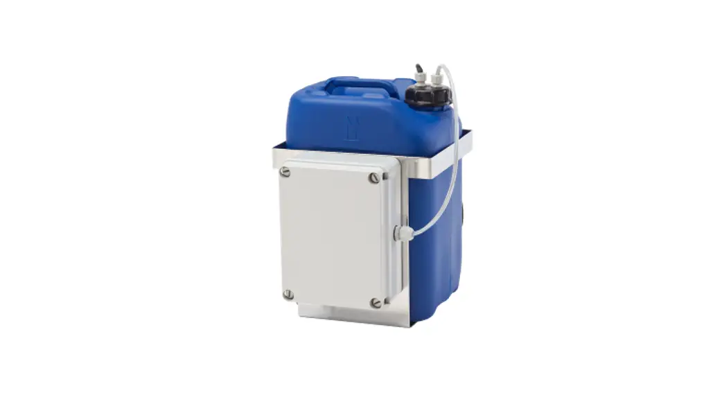
Description
The WP10 series has been designed to operate on camera housings with a wash wiper system, such as the SA industrial/marine camera series, the UP traffic PTZ series, and the HSG04 outdoor housing.
The WP10 is powered by 24 Vac and 100 Vac ~ 240 Vac 50/60Hz supply voltage.
The units can be controlled using a 24 Vac control signal or a dry contact / open collector signal.
The WP10 is fitted with a float switch that prevents the pump from running dry and ndicates an “empty tank” by a contact-closure output.
Before you continue
 | Prior to installation and operation, carefully read all instructions in this manual and heed all warnings. |
| Unpack this equipment and handle it carefully. If the package appears to be damaged, notify the shipper immediately. | |
| Use the original packaging to transport the unit. Disconnect the power supply before moving it. In case of returning the equipment, the original packaging must be used. | |
| Any change performed on the unit that is not previously approved by the anufacturer will void both the EU Declaration of Conformity and its warranty. | |
| This equipment has been designed to fit in harsh environments requiring little or no maintenance. The suggested inspection interval is 6 months, but extremely harsh environments may require more frequent inspection and maintenance checks. On each inspection check cables, electrical connections and mounting hardware for integrity and tightness. Replace or tighten any damaged/loose part, when necessary. | |
| Make sure that the installation surface can support at least four times the weight of a fully filled unit. In case of excessive external stress (e.g. vibration, strong winds or impact), the equipment may need additional means of protection. | |
| Proper stainless steel hardware should be carefully chosen to mount the unit. | |
| Clean the surface of the product with a damp cotton cloth. | |
| To maintain the IP rating of the unit, adequate cable glands must be used. The unit must be tightly closed when operating. | |
| Open only the covers pointed out in this installation manual. | |
| The internal pump must not run dry to prevent failure. A float switch with an “empty tank alarm” is available to prevent such damages. | |
| The unit is intended to be used with water or with water/ethanol solutions. Othermixtures could obstruct the nozzle. If the solution used has residual, it must be filtered before use. Keep the unit empty until the end of the installation. | |
 | Before performing any operation, turn off the power. The installation of the unit can be performed only by qualified personnel in accordance with the relevant local and national standards including but not limited to the use of special pipes, tapes, sealants, cables, and glands. |
| An all-pole mains switch with an opening distance between the contacts at least 3 mm in each pole must be incorporated in the electrical installation. The switch must be equipped with protection against the fault current towards the ground (differential) and the overcurrent (magnetothermal, maximum 15A). It must be very quickly recognizable and readily accessible. A suitable blow fuse must also be installed for protection. | |
| For connection to the mains, use a multipolar cable having minimum 3×1,5 mm2 (15 AWG). The main cable must be at least protected by an ordinary PVC sheath. | |
| Ensure that the unit case is properly earthed, connecting all the earth-ground studs. Earth cable should be about 10mm longer than the other cables on the connector, in such way that it won’t be accidentally disconnected if the cable is stretched or pulled. | |
| Ensure that the unit case is properly earthed, connecting all the earth-ground studs. |
Install the unit
Open the plastic box
 | 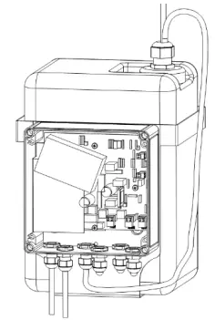 |
- Remove the cover of the plastic box by loosening thefour screws.
- Lead the power supply cable and control cable through the cable glands into the plastic box.
- Tighten the cable glands (with an 3 Nm torque). Do not remove caps from unused cable glands.
- Connect the power cable and control cable according to the instructions below.
- Close the plastic box tightly
- Connect the water hose to the nozzle
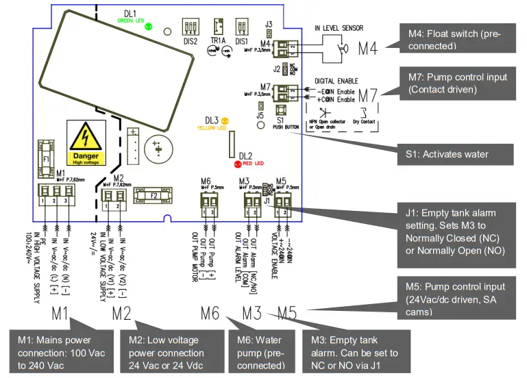
Control boardsettings
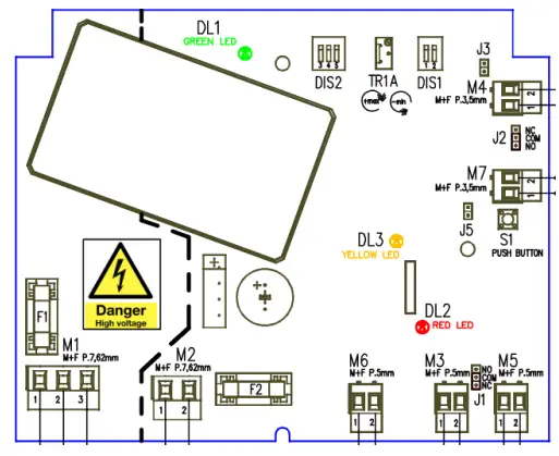
| M1 | WARNING HIGH VOLTAGE Power Supply input 100÷240VAC (+/- 10%) 60W max |
| M2 | Low Voltage Power Supply Input 24VAC/DC (+/- 10%) 60W max |
| M3 | Level Alarm Output: when the tank is empty, normally open or closed based on J1 |
| M4 | Level Sensor Input, connected to a Float Switch, configurable normally open or closed by J2 |
| M5 | Voltage Enable Input, activates the Pump Motor when 24VAC/DC (+/- 10%) is applied |
| M6 | Pump Motor Output, connected to the Water Pump |
| M7 | Digital Enable Input, activates the Water Pump when the input is closed |
| DIS1-1 | Power Supply Input Configuration: 100~240Vac or 24Vdc: SW1= OFF (0) 24Vac (by default) SW1= ON (1) |
| DIS1-2 | Pump Motor Output Level Configuration: SW2 shall always be OFF (0) |
| J1 | Level Alarm Output configuration (NC or NO) |
| J2 | Reserved |
| J3 | reserved |
| J5 | Pump motor Output Enabler turns the Water Pump always ON |
| S1 | Pump Motor Output Test Button, when pressed enables the Water Pump |
| F1 | HIGH VOLTAGE Power Supply Fuse: T 4A (250VAC) |
| F2 | Low Voltage Power Supply Fuse: T 6,3A (250VAC) |
| DL1 | Power Supply GREEN LED turns ON when a power supply is provided |
| DL2 | Water Level Alarm RED LED, turns ON when empty tank is detected |
| DL3 | Pump Motor Output YELLOW LED, turns ON when the Water Pump is enabled |
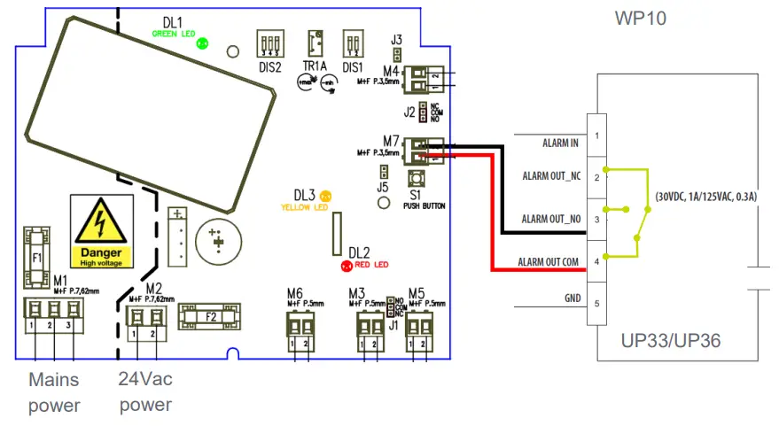
Connecting the UPxx series
The washer control is connected by the ALARM-out wires of the UPxx camera.
| Cable Label | Cable color | Remarks |
| ALARM IN | Black | Not used |
| GND | Brown | |
| ALARM OUT NO | Red | Normally open (Washer) |
| ALARM OUT NC | Orange | Normally closed |
| ALARM OUT COM | Yellow | Common (Washer) |
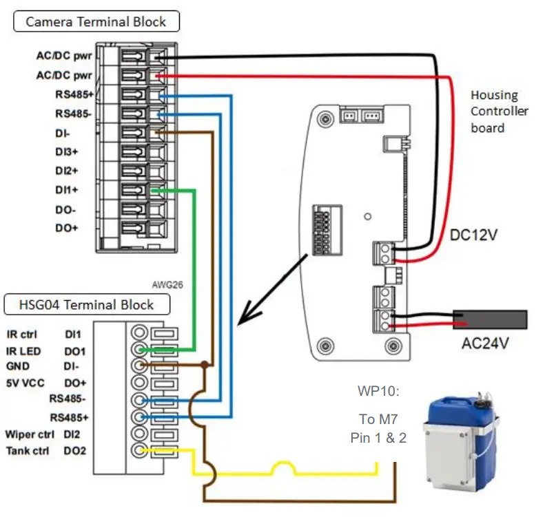
Connecting the HSG04
The washer is controlled by alarm output (DO2) from HSG04. The movement will be maintained by a camera installed in HSG04. For detailed configuration please refer to the HSG04 quick start guide.
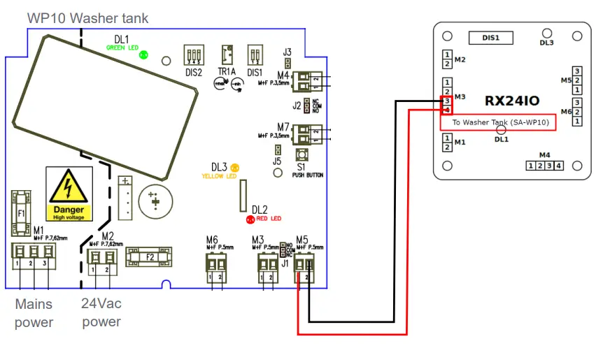
Connecting the SA camera series
Connecting a WP10 to an SA-PTZ
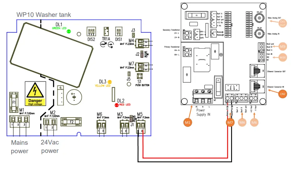
Connecting a WP10 to an SA-FIX W
Dimensions
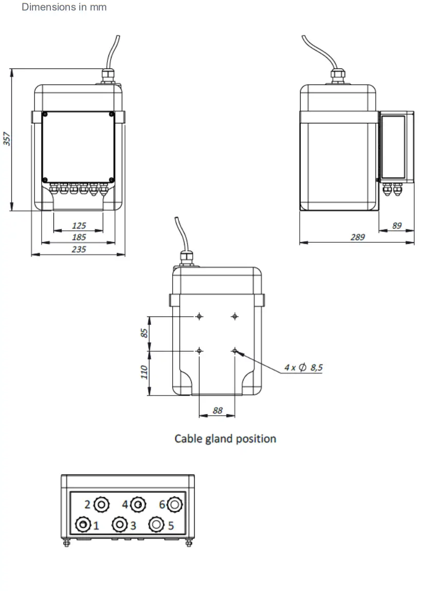
| 1 | Input voltage |
| 2 | Enable |
| 3 | Float switch |
| 4 | Pump |
| S | Cable gland with blank |
| 6 | Alarm |
 TKH SECURITE
tkhsecurity.com ![]() © 2021, TKH Security
© 2021, TKH Security


