![]()
Installation Guide
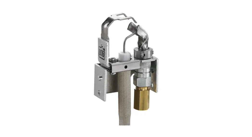
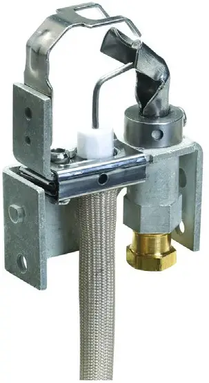
Q3451U
Universal Pilot Burner

Cross Reference (Use only as a replacement for these Resideo pilots)
| Old Part # | Set Hood | Use Orifice† | Compression Fitting | Igniter Lead |
| 03451B1004 | L | Orange Bag | 1/4 in. | 36 in. |
| 03451B1079 | F | Purple Bag | 1/4 in. | 36 in. |
| 03451B1095 | F | Orange Bag | 1/4 in. | 36 in. |
| 03451B1103 | L | Orange Bag | 1/4 in. | 55 in. |
| 3451131178 | L | Orange Bag | 1/4 in. | 55 in. |
| 3451131186 | F | Orange Bag | 1/4 in. | 55 in. |
| 345181194 | F | Purple Bag | 1/4 in. | 55 in. |
| 345181236 | L | Gray Bag | 1/4 in. | 55 in. |
| 03451B1244 | L | Orange Bag | 1/4 in. | 55 in. |
| 03451B1301 | L | As Shipped | 1/4 in. | 36 in. |
| 03451B1707 | L | Red Bag | 1/4 in. | 36 in. |
| 03451B1715 | L | * | 1/4 in. | 36 in. |
| 03451B2002 | F | Orange Bag | 1/4 in. | 36 in. |
| 03451B2010 | F | Orange Bag | 1/8 in. | 36 in. |
| 03451B2036 | F | Orange Bag | 1/4 in. | 36 in. |
| 03451B2044 | F | Orange Bag | 1/4 in. | 55 in. |
| Q3451B2077 | F | As Shipped | 1/4 in. | 36 in. |
| Q3451B2085 | F | Gray Bag | 1/4 in. | 36 in. |
| Q3451B2101 | F | Orange Bag | 1/4 in. | 55 in. |
| Q3451B3018 | R | Orange Bag | 1/4 in. | 36 in. |
| 345183026 | R | Orange Bag | 1/8 in. | 36 in. |
| 345183067 | R | Orange Bag | 1/4 in. | 36 in. |
| 345183083 | R | Orange Bag | 1/4 in. | 36 in. |
| Q3451BF | F | * | * | * |
| Q3451BK | R | * | * | * |
| Q3451BL | L | * | * | * |
| 03451 K2002 | F | As Shipped | 1/4 in. | 55 in. |
| 03451 K2010 | F | Gray Bag | 1/4 in. | 55 in. |
| 03451 K2028 | F | As Shipped | 1/4 in. | 55 in. |
| 03451KF | F | * | * | * |
| 03451U1000 | * | * | * | * |
| Key | Set Hood To | L = 20° Left | Ignitor Lead | 36″ (As Shipped) 55” (Packed separately) |
| F = Front | ||||
| R = 20° Right | ||||
| Use Orifice | As Shipped = BCR-20 (0.020 in) Natural gas | |||
| Orange Bag = BCR-18 (0.018 in.) Natural gas | ||||
| Purple Bag = BCR-10 (0.010 in.) LP gas | ||||
| Gray Bag = BBR-12 (0.012 in.) LP gas | ||||
| † | Red Bag = BBR-11 (0.011 in.) LP gas Colors refer to the color of the label on the bag. |
Note
This pilot replaces only Resideo standard single-rod, hood-style intermittent pilot burners with integral ignition and a sensing wire.
It will not replace batwing-style pilot burners or pilot burners without an integral ignition and sensing wire.
- For the intermittent pilot, batwing style pilot burners without an integral ignition and sensing wire see the Q348U.
- For the intermittent pilot, hood style pilot burners without an integral ignition and sensing wire see the Q345U.
- For standing pilot hood style pilot burners, see the Q314U.
The specifications given here do not include normal manufacturing tolerances. Therefore, this unit may not exactly match the listed specifications. This product is tested and calibrated under closely controlled conditions, and some minor differences in performance should be expected if those conditions are changed.
WHEN INSTALLING THIS PRODUCT…
- Read these instructions carefully. Failure to follow instructions can damage equipment or cause a hazardous condition.
- Check cross-reference in the installation guide or box to verify the pilot is suitable for your application.
- The installer must be a trained, experienced service technician.
- After completing the installation, use these instructions to check out product operation.
 WARNING
FIRE OR EXPLOSION HAZARD. CAN CAUSE PROPERTY DAMAGE, SEVERE INJURY, OR DEATH.
Follow these warnings exactly:
- Disconnect power supply before wiring to prevent electrical shock or equipment damage.
- To avoid the dangerous accumulation of fuel gas, turn off the gas supply at the appliance service valve before starting the installation and perform Gas Leak Test after completion of installation.
- . Do not bend pilot tubing within 3 inches of the gas control or pilot burner after the compression nut has been tightened. Gas leakage at the connection can result.
Follow the appliance manufacturer instructions, if available; otherwise, use the instructions provided.
Remove the Old Pilot Burner
A Make sure gas is shut off.
B Remove old Pilot Burner, including the old compression fitting.
C Match the old model number to the Cross Reference.
D Use the information in the Cross Reference to install the Pilot Burner.
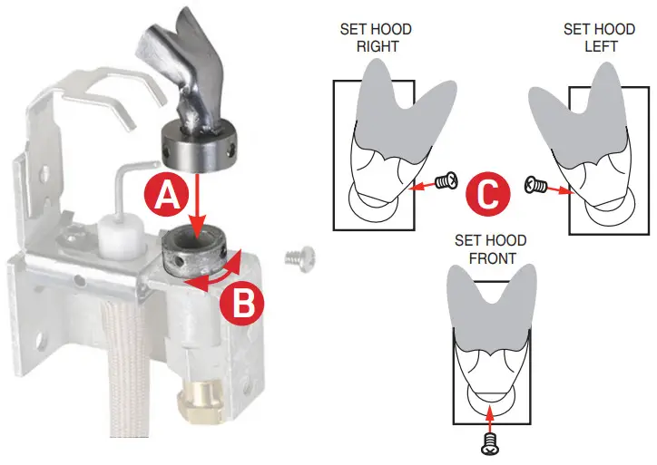
Set the Hood
See Cross Reference for the position.
WARNING
FIRE OR EXPLOSION HAZARD. CAN CAUSE PROPERTY DAMAGE, SEVERE INJURY, OR DEATH.
Pilot flame must be positioned in the exact same position with respect to the main burner. The screw must be installed through the pilot hood and into the spud, so the head of the screw is flush with the adapter. Failure to properly orient the pilot flame and/or secure the pilot hood may create an explosion hazard.
Mount Pilot Burner
Use the included screws to mount the Pilot Burner.
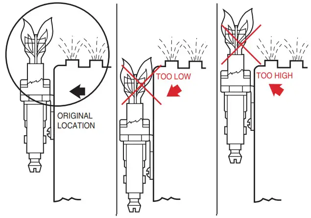
Position the Pilot Burner so the pilot flame is aimed at the main burner exactly the same way as the original pilot burner flame.
WARNING
FIRE OR EXPLOSION HAZARD. CAN CAUSE PROPERTY DAMAGE, SEVERE INJURY, OR DEATH.
Pilot burner flame alignment to the main burner is critical to safe appliance operation. Carefully read all installation instructions. Replace only those pilots listed in the literature.
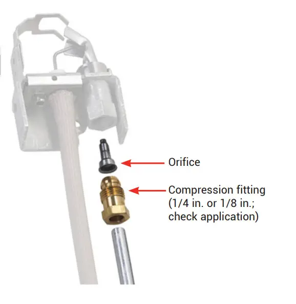
Install the Correct Orifice and Compression Fitting
See Cross Reference for orifice and sizes.
Cut off the old compression fitting and replace it with the new compression fitting provided with the new pilot burner. Never use the old compression fitting because it might not provide a gas-tight seal.
WARNING
FIRE OR EXPLOSION HAZARD. CAN CAUSE PROPERTY DAMAGE, SEVERE INJURY, OR DEATH.
The orifice must be the same size as the original orifice.
Connect the Ignition Cable and Ground Wire
The igniter-sensor must be mounted on the pilot burner before connecting the wires.
Use the 36 in. or 55 in. igniter lead as specified in the Cross Reference or as required by the application.
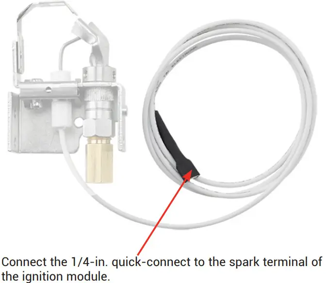
NOTE: Connect ground wire if present or applicable.
Gas Leak Test and Checkout
Gas Leak Test
A Make sure the warning card has been removed from the pilot.
B Turn on gas supply.
C Use a gas sniffer* or paint the pipe connections upstream of the pilot burner with a rich soap and water solution to check for leaks. Bubbles indicate a gas leak.
D If a leak is detected, tighten the pipe connections.
E Stand clear of the main burner while lighting to prevent injury from hidden leaks, which can cause flashbacks in the appliance vestibule.
F Set the thermostat to call for heat to light the main burner.
G With the main burner in operation, paint the pipe joints (including the adapters) and gas control inlet and outlet with rich soap and water solution or use a gas sniffer* to check for leaks.
H If another leak is detected, tighten the adapter screws, joints, and pipe connections.
I Replace the part if the leak cannot be stopped.
J Do not proceed until all gas leaks are eliminated.
* See AHRI video for proper use and considerations when using an electronic gas sniffer
Checkout
Cycle the furnace through several cycles to ensure proper smooth light off.
WARNING
FIRE OR EXPLOSION HAZARD. CAN CAUSE PROPERTY DAMAGE, SEVERE INJURY, OR DEATH.
Check for gas leaks any time work is done on a gas system.
Adjust Pilot Flame
The pilot flame should envelop 1/4 to 1/2 in. (6 to 13 mm) of the igniter-sensor tip.
A Turn off the system.
B Disconnect the lead to the MV terminal on the gas control Light the pilot by setting the thermostat above room temperature to call for heat.
D Remove the pilot adjustment cover screw from the gas control.
E Turn the inner pilot adjustment screw clockwise to decrease or counterclockwise to increase the pilot flame.
F Replace the pilot adjustment cover screw and tighten firmly after adjustment is complete to ensure proper operation.
NOTE: If Pilot flame is too small and cannot be adjusted to a larger size, a larger orifice may be needed. Check application requirements. If the Pilot flame is too large and cannot be adjusted to a smaller size, a smaller orifice may be needed. Check application requirements
WARNING
FIRE OR EXPLOSION HAZARD. CAN CAUSE PROPERTY DAMAGE, SEVERE INJURY, OR DEATH.
Using the incorrect orifice or pilot hood can cause an unstable pilot, too large or too small of a pilot, pilot out- age, reduced pilot life, improper light off, or gas buildup.
![]() Resideo Technologies Inc.
Resideo Technologies Inc.
1985 Douglas Drive North,
Golden Valley, MN 55422
1-800-468-1502
69-2757ES—02 M.S. Rev. 03-21
Printed in the United States
© 2021 Resideo Technologies, Inc. All rights reserved.
This product is manufactured by Resideo Technologies, Inc. and its affiliates.


