![]() EM ConverterLED Basic 104 200V
EM ConverterLED Basic 104 200V
Instructions
Emergency lighting units
EM converterLED
EM converterLED BASIC 200 V
Emergency lighting LED Driver

Product description
- Emergency lighting LED Driver for manual testing
- For LED modules with a forward voltage of 50 – 200 V
- Low profile casing (21 x 30 mm cross-section)
- For luminaire installation
- 5-year guarantee
Properties
- Non maintained operation
- 1 or 3 h rated duration
- Operating time selectable with plug (duration link)
- Compatible with all dimmable and non-dimmable constant current LED Drivers (see LED Driver compatibility, page 6)
- 3-pole technology: 2-pole LED module changeover and delayed power switching for the LED Driver
- Automatic shutdown of output if LED load is out of range
- Constant power output
- Maximum light output for all LED modules
- Electronic charge system
- Deep discharge protection
- Short-circuit-proof battery connection
- Polarity reversal protection for battery
Batteries
- High-temperature cells
- NiCd or NiMH batteries
- D, Cs or LA cells
- 4-year design life
- 1-year guarantee
![]()
Standards, page 7
Wiring diagrams and installation examples, page 8
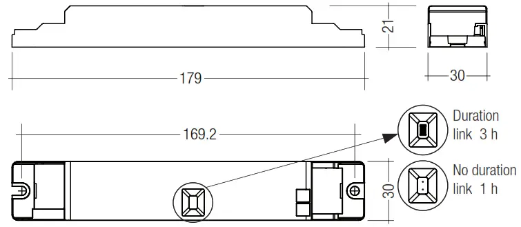
Note: LED Driver supplied with duration link in 3 hours position. Remove duration link for 1 hour duration. Duration link must be set before battery and mains connection.
Technical data
| Rated supply voltage | 220 – 240 V |
| Mains frequency | 50 / 60 Hz |
| Typ. λ (at 230 V, 50 Hz) | 0.55 |
| LED module forward voltage range | 50 – 200 V |
| Output current | see page 4 |
| Time to light | < 0.25 s from detection of emergency event |
| Overvoltage protection | 320 V (for 1 h) |
| Maximum output voltage | 250 V |
| Battery charging time | 20 h① |
| Ambient temperature range ta | -5 … + 55 °C |
| Max. casing temperature tc | 70 °C |
| Mains voltage changeover threshold | according to EN 60598-2-22 |
| Type of protection | IP20 |
① 16 h battery charging time for 2 h emergency lighting function according to AS 2293.
Ordering data
| Type | Article number | Rated duration | Number of cells | Packaging,carton | Packaging, pallet | Weight per pc. |
| EM converterLED BASIC 104 200V | 89800308 | 1/3 h | 4 | 10 pc(s). | 800 pc(s). | 0.078 kg |
| EM converterLED BASIC 105 200V | 89800309 | 1/3 h | 5 | 10 pc(s). | 800 pc(s). | 0.078 kg |
Specific technical data
| Type | Rated duration | Max. output power | Mains current in charging operation | Rated power in charging operation |
| EM converterLED BASIC 104 200V | 1 h | 3.85 W | 25 mA | 3.0 W |
| 3 h | 3.85 W | 30 mA | 4.0 W | |
| EM converterLED BASIC 105 200V | 1 h | 4.85 W | 25 mA | 3.0 W |
| 3 h | 4.85 W | 30 mA | 4.5 W |
ACCESSORIES
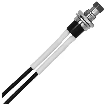
Test switch EM3
Product description
- For connection to the emergency lighting unit
- For checking the device function
- Plug connection

ACCESSORIES
Status indication green LED
Product description
- A green LED indicates that charging current is flowing into the battery
- Plug connection

Ordering data
| Type | Article number | Packaging,bag | Packaging,carton | Weight per pc. |
| LED EM green, 1.0 m CON | 89800269 | 25 pc(s). | 200 pc(s). | 0.015 kg |
| LED EM green, HO 1.0 m CON | 89800271 | 25 pc(s). | 200 pc(s). | 0.015 kg |
| LED EM green, 0.6 m CON | 89800472 | 25 pc(s). | 200 pc(s). | 0.005 kg |
| LED EM green, HO 0.6 m CON | 89800473 | 25 pc(s). | 200 pc(s). | 0.005 kg |
| LED EM green, 0.3 m CON | 89800270 | 25 pc(s). | 200 pc(s). | 0.005 kg |
| LED EM green, HO 0.3 m CON | 89800272 | 25 pc(s). | 200 pc(s). | 0.005 kg |
Battery selection
EM converterLED BASIC, 1 / 3 h
| Type | EM converterLED BASIC 104 200V | EM converterLED BASIC 105 200V | ||
| Article no. | 89800308 | 89800309 | ||
| Cells | 4 cells | 5 cells | ||
| Duration | 1 h | 3 h | 1 h | 3 h |
| Technology and capacity Design | Article no. | Assignable batteries | |||||
| NiCd 1.6 AhCs cells | stick | 1 x 4 Accu-NiCd C 4A | 89899692 | • | |||
| stick | 1 x 5 Accu-NiCd C 5A | 89899695 | • | ||||
| stick + stick | 2 + 2 Accu-NiCd C 4C | 89899694 | • | ||||
| stick + stick | 3 + 2 Accu-NiCd C 5C | 89899697 | • | ||||
| side by side | 4 x 1 Accu-NiCd C 4B | 89899693 | |||||
| side by side | 5 x 1 Accu-NiCd C 5B | 89899696 | • | ||||
| NiCd 4 Ah D cells① | stick | 1 x 4 Accu-NiCd 4A 55 | 89800089 | • | |||
| stick | 1 x 5 Accu-NiCd 5A | 89895973 | • | ||||
| stick + stick | 2 + 2 Accu-NiCd 4C | 89895978 | • | ||||
| stick + stick | 3 + 2 Accu-NiCd 5C 55 | 89800090 | • | ||||
| side by side | 4 x 1 Accu-NiCd 4B 55 | 89800385 | • | ||||
| NiMH 2 Ah Cs cells | stick | 1 x 4 Accu-NiMH C 4A | 89899700 | • | |||
| stick | 1 x 5 Accu-NiMH C 5A | 89899703 | • | ||||
| side by side | 5 x 1 Accu-NiMH C 5B | 89899704 | • | ||||
| NiMH 4 Ah LA cells | stick | 1 x 4 Accu-NiMH 4Ah 4A CON | 89800442 | • | |||
| stick + stick | 2 + 2 Accu-NiMH 4Ah 4C CON | 89800438 | • | ||||
| stick + stick | 3 + 2 Accu-NiMH 4Ah 5C CON | 89800439 | • | ||||
① 50 °C batteries also available (see seperate datasheet at www.tridonic.com)
Battery charge/discharge data
EM converterLED BASIC, 1/3 h
| Type | EM converterLED BASIC 104 200V | EM converterLED BASIC 105 200V | ||
| Article no. | 89800308 | 89800309 | ||
| Cells | 4 cells | 5 cells | ||
| Duration | 1 h | 3 h | 1 h | 3 h |
| Charging current | 105 mA | 210 mA | 105 mA | 210 mA |
| Discharge current | 750 – 960 mA | 750 – 960 mA | 750 – 960 mA | 750 – 960 mA |
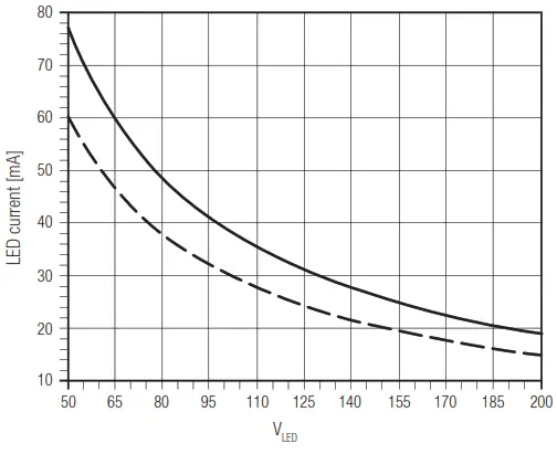
Typ. LED current/voltage characteristics
The LED current in emergency mode is automatically adjusted by the EM converterLED module based on the total forward voltage of the LED modules connected and the associated battery.
EM converterLED BASIC 104 200V
Article number: 89800308
4.8 V battery voltage
750 – 960 mA battery discharge current (tolerance)
| LED peak current at start in emergency mode – 4 cells | ||
| Voltage | Inrush current | Duration |
| 52.1 V | 146 mA | 16.7 ms |
| 62.0 V | 134 mA | 14.1 ms |
| 74.7 V | 121 mA | 11.5 ms |
| 84.8 V | 111 mA | 9.4 ms |
| 100.0 V | 100 mA | 7.7 ms |
| 110.1 V | 94 mA | 6.9 ms |
| 122.6 V | 86 mA | 6.3 ms |
| 135.1 V | 81 mA | 4.3 ms |
| 145.0 V | 77 mA | 4.2 ms |
| 155.8 V | 73 mA | 3.7 ms |
| 168.3 V | 68 mA | 3.0 ms |
| 180.8 V | 57 mA | 2.9 ms |
| 190.8 V | 51 mA | 2.1 ms |
| 200.6 V | 36 mA | 2.0 ms |
EM converterLED BASIC 105 200V
Article number: 89800309
6.0 V battery voltage
750 – 960 mA battery discharge current (tolerance)
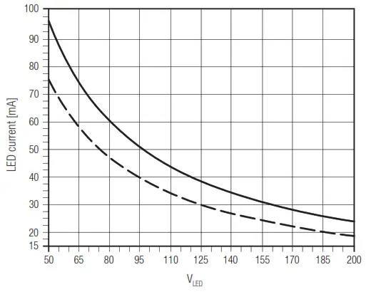
| LED current at nominal battery voltage and min. battery discharge current | |
| LED current at nominal battery voltage and max. battery discharge current |
| LED peak current at start in emergency mode – 5 cells | ||
| Voltage | Inrush current | Duration |
| 52.3 V | 136 mA | 25.7 ms |
| 62.5 V | 127 mA | 18.9 ms |
| 75.3 V | 118 mA | 14.9 ms |
| 85.4 V | 111 mA | 12.4 ms |
| 100.7 V | 102 mA | 9.6 ms |
| 110.8 V | 97 mA | 8.4 ms |
| 123.3 V | 92 mA | 7.6 ms |
| 135.9 V | 86 mA | 6.6 ms |
| 145.9 V | 81 mA | 5.8 ms |
| 155.9 V | 80 mA | 5.3 ms |
| 171.0 V | 73 mA | 4.4 ms |
| 181.0 V | 69 mA | 3.9 ms |
| 191.1 V | 67 mA | 3.2 ms |
| 201.1 V | 65 mA | 3.0 ms |
Note: LED peak current measured at the max. battery discharge current and at a max. battery voltage of 6 V (4 cells) or 7.5 V (5 cells).
Isolation and electric strength testing of luminaires
Electronic LED Drivers can be damaged by high voltage. This has to be considered during the routine testing of the luminaires in production.
According to IEC 60598-1 Annex Q (informative only!) or ENEC 303-Annex A, each luminaire should be submitted to an isolation test with 500 VDC for 1 second. This test voltage should be connected between the interconnected phase and neutral terminals and the earth terminal. The isolation resistance must be at least 2 MΩ.
As an alternative, IEC 60598-1 Annex Q describes a test of the electrical strength with 1,500 VAC (or 1,414 x 1,500 VDC). To avoid damage to the electronic devices this test must not be conducted.
Technical data batteries
Accu-NiCd
Case temperature range to ensure 4 years design life
4.2/4.5 Ah D: +5 °C to +55 °C
1.6 Cs: +5 °C to +50 °C
Battery voltage/cell: 1.2 V
Single cell dimensions
4.2/4.5 Ah D
Diameter: 32.5 mm
Height: 60.5 mm
1.6 Ah Cs
Diameter: 22.5 mm
Height: 42.5 mm
Capacity D: 4.2 / 4.5 Ah
Capacity Cs: 1.6 Ah
Max. short term temperature (reduced life-time): 70 °C
Max. number discharge cycles: 4 cycles per year plus 4 cycles during comissioning
Packing quantity : 5 pcs. per carton
Accu-NiMh
Case temperature range to ensure 4 years design life
2.0 Ah Cs: +5 °C to +55 °C
4.0 Ah LA: +5 °C to +40 °C
Battery voltage: 1.2 V
Single cell dimensions
2.0 Ah Cs
Diameter: 22 mm
Height: 42.5 mm
4.0 Ah LA
Diameter: 18.3 mm
Height: 90 mm
Capacity Cs/LA: 2.0 Ah / 4.0 Ah
Max. short term temperature (reduced life-time): 70 °C
Max. number discharge cycles 2.0 Ah Cs: 4 cycles per year plus 4 cycles during comissioning
Max. number discharge cycles 4.0 Ah LA: 2 cycles per year plus 4 cycles during comissioning
Packing quantity: 5 pcs. per carton
Storage, installation and commissioning
Relevant information about storage conditions, installation and commissioning are provided in the battery datasheets.
LED Driver compatibility
The EM converterLED emergency unit use 3 pole technology and is compatible with most LED Drivers on the market, however it is important to check that the rating of the LED Driver does not exceed the values specified below:
- The max. allowed output current rating of the associated LED Driver is 2.4 A peak (current rating of switching relays of EM converterLED)
- The max. allowed inrush current rating of the associated LED Driver is 60 A peak for 1 ms (inrush current rating of switching relay of EM converterLED)
- The max. allowed output voltage of the associated LED Driver applied to the EM converterLED output is 450V (voltage withstand between adjacent contact of the single switching relay of the EM converterLED)
The max. allowed LED load of the associated LED Driver is 150 W in operation. The load must be an LED module.
Life-time
Average life-time 50,000 hours under rated conditions with a failure rate of less than 10 %. Average failure rate of 0.2 % per 1000 operating hours.
Maximum lead length
| LED | 3 m① |
| Status indication LED | 1 m |
| Batteries | 1.3 m |
① Note: The length of LED leads to the LED module must not be exceeded. Note that the length of the EM converterLED leads is added to the length of the leads from the LED Driver to the EM converterLED module when considering max. permitted lead length of the LED Driver. Leads should always be kept as short as possible.
Mechanical details
Casing manufactured from polycarbonate.
Glow-wire test according to EN 61347-1 with increased temperature of 960 °C passed.
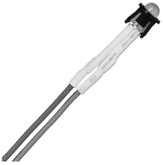
LED status indicator
- Green
- Mounting hole 6.5 mm dia
- Lead length 0.3 m / 1.0 m
- Insulation rating: 90 °C
- Plug connection
Test switch
- Mounting hole 7.0 mm dia
- Lead length 0.55 m
- Plug connection
Battery leads
- Quantity: 1 red and 1 black
- Length: 1.3 m
- Wire type: 0.5 mm² solid conductor
- Insulation rating: 90 °C
Battery end termination
Push on 4.8 mm receptacle to suit battery spade fitted with insulating cover
Module end termination: 8.0 mm stripped insulation
Two-piece batteries are supplied with a 200 mm lead with 4.8 mm receptacle at each end and insulting covers to connect the separate sticks together.
Electrical connections
Wiring
LED module/LED Driver/supply
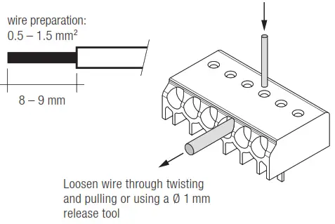
Wiring type and cross section
Solid wire with a cross section of 0.5 – 1.5 mm². Strip 8 – 9 mm of insulation from the cables to ensure perfect operation of terminals.
Batteries
Connection method: 4.8 x 0.5 mm spade tag welded to end of cell.
For stick packs this connection is accessible after the battery caps have been fitted.
To inhibit inverter operation disconnect the batteries by removing the connector from the battery spade tag.
For battery data see separate data sheet.
Phase to phase isolation
The use of different phases for switched line and unswitched line is permitted.
Standards
- according to EN 50172
- according to EN 60598-2-22
- EN 61347-1
- EN 61347-2-13
- EN 61347-2-7
- EN 55015
- EN 61000-3-2
- EN 61000-3-3
- EN 61547
- EN 60068-2-64
- EN 60068-2-29
- EN 60068-2-30
- EN 62384
Duration link selection
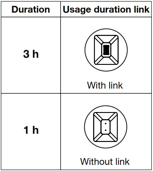
Emergency lighting LED Driver supplied with duration link in 3 hours position.
The position of the link will only be read on first power up. If it is changed afterwards both the battery and mains supply must be disconnected for 10 seconds to enable the EM converterLED to read the new link position on reconnection of the battery and mains. It will lead to a false battery failure indication if the link is changed after installation without this reset.
Wiring guidelines
- The LED terminals, battery, indicator LED and test switch terminals are classified as SELV (output voltage < 120 V DC). Keep the wiring of the input terminals separated from the wiring of the SELV equivalent terminals or consider special wiring (double insulation, 6 mm creepage and clearance) when these connections should be kept SELV.
- The output to the LED is DC but has high frequency content, which should be considered for good EMC compliance.
- LED leads should be separated from the mains connections and wiring for good EMC performance.
- Maximum lead length on the LED terminals is 3 m. For a good EMC performance keep the LED wiring as short as possible.
- Maximum lead length for the Test switch and Indicator LED connection is 1 m. The test switch and Indicator LED wiring should be separated from the LED leads to prevent noise coupling.
- Battery leads are specified with 0.5 mm cross section and a length of 1.3 m
To ensure that a luminaire containing LED emergency units complies with EN 55015 for radio frequency conducted interference in both normal and emergency mode it is essential to follow good practice in the wiring layout.
Within the luminaire the switched and unswitched 50 Hz supply wiring must be routed as short as possible and be kept as far away as possible from the LED leads.
Through wiring may affect the emc performance of the luminaire.
The length of LED leads must not be exceeded. Note that the length of the EM converterLED leads is added to the length of the leads from the LED Driver to the EM converterLED module when considering max. permitted lead length of the LED Driver.
Maximum loading of automatic circuit breakers
| Automatic circuit breaker type | B10 | B13 | B16 | B20 | C10 | C13 | C16 | C20 | Inrush current | |
| Installation Ø | 1.5 mm² | 1.5 mm² | 1.5 mm² | 1.5 mm² | 1.5 mm² | 1.5 mm² | 1.5 mm² | 1.5 mm² | Imax | time |
| EM converterLED 104 BASIC 200V | 90 | 130 | 130 | 130 | 180 | 260 | 260 | 260 | 10:00 AM | 120 μs |
| EM converterLED 105 BASIC 200V | 90 | 130 | 130 | 130 | 180 | 260 | 260 | 260 | 10:00 AM | 120 μs |
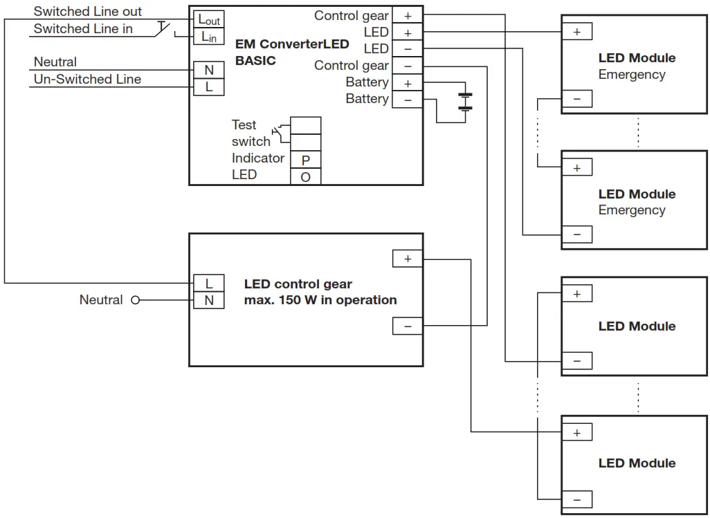
Wiring diagrams
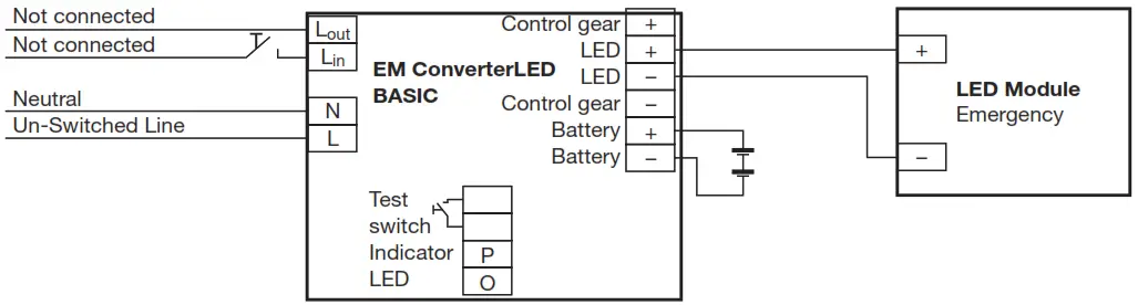
One or more LED modules with a total forward voltage of 50 to 200 V can be connected to the EM converterLED 200V module. These LED module(s), marked with “Emergency” are operated in emergency mode from the associated battery. In normal mains mode all LED modules are operated by the mains LED Driver.
Use of the test switch:
For checking the device function press the test switch for a minimum of 3 seconds.
EM converterLED BASIC with one LED module for non-maintained emergency operation
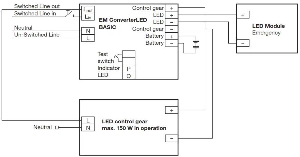
EM converterLED BASIC with a standard LED Driver and one LED module for mains and emergency operation
EM converterLED BASIC with a standard LED Driver and series operation of LED modules
One LED module is operated in emergency mode.
All LED modules are operated in mains mode.
EM converterLED BASIC with a standard LED Driver and series operation of LED modules
Two or more LED modules are operated in emergency mode.
All LED modules are operated in mains mode.
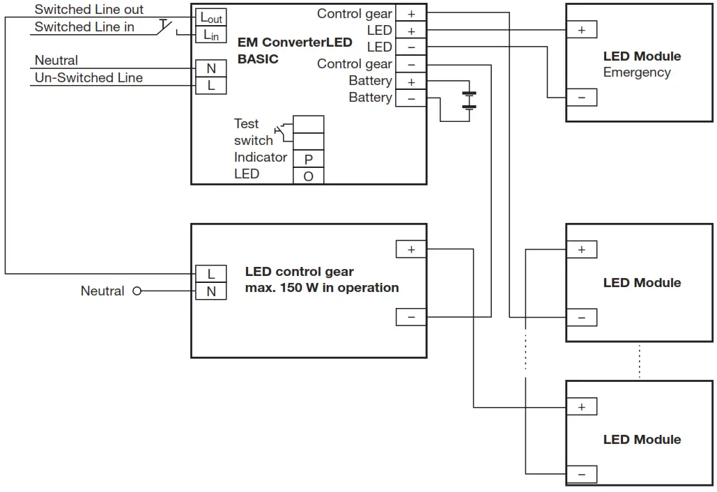
EM converterLED BASIC with a standard LED Driver and parallel operation of LED modules
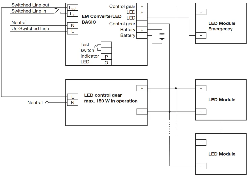
One LED module is operated in emergency mode.
All LED modules are operated in mains mode.
EM converterLED BASIC with a standard LED Driver and parallel operation of LED modules
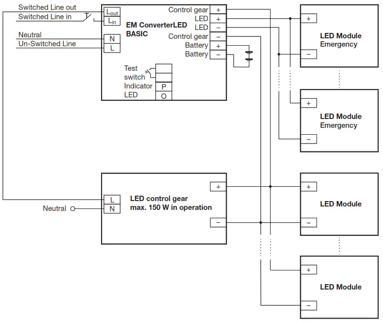
Two or more LED modules are operated in emergency mode.
All LED modules are operated in mains mode.
Additional information
Additional technical information at www.tridonic.com → Technical Data
Guarantee conditions at www.tridonic.com → Services
Life-time declarations are informative and represent no warranty claim. No warranty if device was opened.
![]() Subject to change without notice.
Subject to change without notice.
Data sheet 05/16-EM034-11
www.tridonic.com![]()


