![]()
TO21-JS0
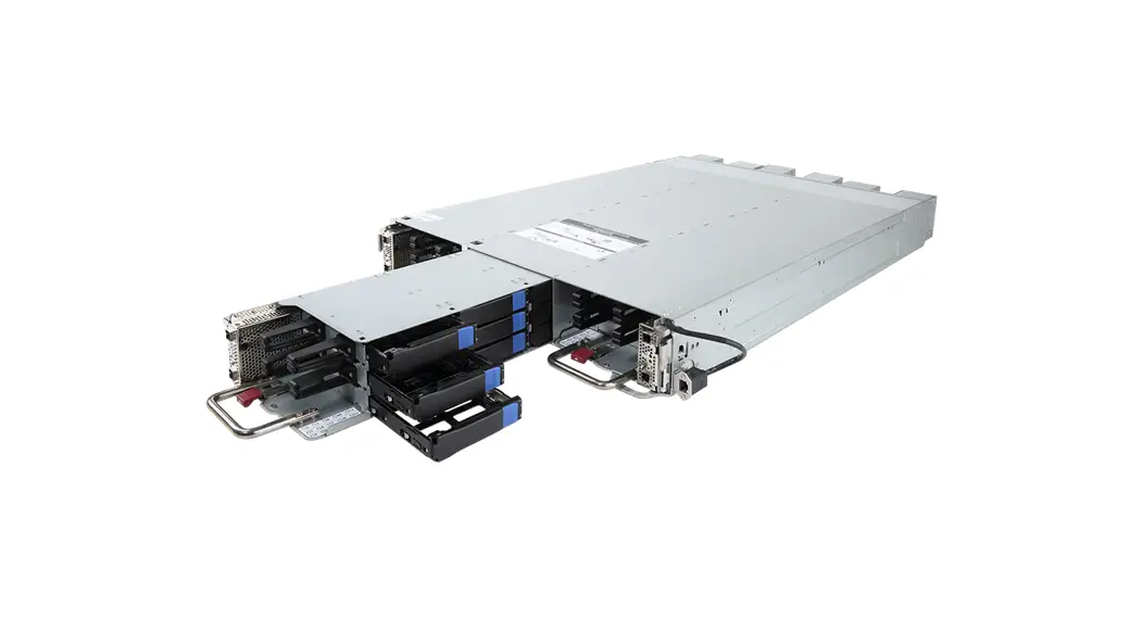
Storage Node
System Installation Guide
Rev. 1.0
TO21-JS0 Storage Node
Copyright
© 2022 GIGA-BYTE TECHNOLOGY CO., LTD. All rights reserved.
The trademarks mentioned in this manual are legally registered to their respective owners.
Disclaimer
Information in this manual is protected by copyright laws and is the property of GIGABYTE. Changes to the specifications and features in this manual may be made by GIGABYTE without prior notice. No part of this manual may be reproduced, copied, translated, transmitted, or published in any form or by any means without GIGABYTE’s prior written permission.
Documentation Classifications
In order to assist in the use of this product, GIGABYTE provides the following types of documentation:
- User Manual: detailed information & steps about the installation, configuration and use of this product (e.g. motherboard, server barebones), covering hardware and BIOS.
- System Installation Guide: detailed information & steps about the installation, configuration and use of this product
- User Guide: detailed information about the installation & use of an add-on hardware or software component (e.g. BMC firmware, rail-kit) compatible with this product.
- Quick Installation Guide: a short guide with visual diagrams that you can reference easily for installation purposes of this product (e.g. motherboard, server barebones).
Please see the support section of the online product page to check the current availability of these documents.
For More Information
For related product specifications, the latest firmware and software, and other information please visit our website at http://www.gigabyte.com
For GIGABYTE distributors and resellers, additional sales & marketing materials are available from our reseller portal: http://reseller.b2b.gigabyte.com
For further technical assistance, please contact your GIGABYTE representative or visit https://esupport.gigabyte.com/ to create a new support ticket
For any general sales or marketing enquiries, you may also message GIGABYTE server directly by email: [email protected]
Conventions
The following conventions are used in this user’s guide:
| NOTE! Gives bits and pieces of additional information related to the current topic. | |
| CAUTION! Gives precautionary measures to avoid possible hardware or software problems. | |
| WARNING! Alerts you to any damage that might result from doing or not doing specific actions. |
Server Warnings and Cautions
Before installing a server, be sure that you understand the following warnings and cautions.
![]() WARNING!
WARNING!
To reduce the risk of electric shock or damage to the equipment:
- Do not disable the power cord grounding plug. The grounding plug is an important safety feature.
- Plug the power cord into a grounded (earthed) electrical outlet that is easily accessible at all times.
- Unplug all the power cords from the power supplies to disconnect power to the equipment.

- Shock Hazard! Disconnect all power supply cords before servicing.
- Do not route the power cord where it can be walked on or pinched by items placed against it.
Pay particular attention to the plug, electrical outlet, and the point where the cord extends from the server.
![]() WARNING!
WARNING!
To reduce the risk of personal injury from hot surfaces, allow the drives and the internal system components to cool before touching them.![]() WARNING!
WARNING!
This server is equipped with high speed fans. Keep away from hazardous moving fan blades during servicing.![]() WARNING!
WARNING!
This equipment is intended to be used in Restrict Access Location. The access can only be gained by Skilled person. Only authorized by well trained professional person can access the restrict access location.
![]() CAUTION!
CAUTION!
- Do not operate the server for long periods with the access panel open or removed. Operating the server in this manner results in improper airflow and improper cooling that can lead to thermal damage.
- Danger of explosion if battery is incorrectly replaced.
- Replace only with the same or equivalent type recommended by the manufacturer.
- Dispose of used batteries according to the manufacturer’s instructions.
Electrostatic Discharge (ESD)![]() CAUTION!
CAUTION!
ESD CAN DAMAGE DRIVES, BOARDS, AND OTHER PARTS. WE RECOMMEND THAT YOU PERFORM ALL PROCEDURES AT AN ESD WORKSTATION. IF ONE IS NOT AVAILABLE, PROVIDE SOME ESD PROTECTION BY WEARING AN ANTI-STATIC WRIST STRAP ATTACHED TO CHASSIS GROUND —
ANY UNPAINTED METAL SURFACE — ON YOUR SERVER WHEN HANDLING PARTS.
Always handle boards carefully. They can be extremely sensitive to ESD. Hold boards only by their edges without any component and pin touching. After removing a board from its protective wrapper or from the system, place the board component side up on a grounded, static free surface. Use a conductive foam pad if available but not the board wrapper. Do not slide board over any surface.
System power on/off: To remove power from system, you must remove the system from rack. Make sure the system is removed from the rack before opening the chassis, adding, or removing any non hot-plug components.
Hazardous conditions, devices and cables: Hazardous electrical conditions may be present on power, telephone, and communication cables. Turn off the system and discon-nect the cables attached to the system before servicing it. Otherwise, personal injury or equipment damage can result.
Electrostatic discharge (ESD) and ESD protection: ESD can damage drives, boards, and other parts. We recommend that you perform all procedures in this chapter only at an ESD workstation. If one is not available, provide some ESD protection by wearing an antistatic wrist strap attached to chassis ground (any unpainted metal surface on the server) when handling parts.
ESD and handling boards: Always handle boards carefully. They can be extremely sensi-tive to electrostatic discharge (ESD). Hold boards only by their edges. After removing a board from its protective wrapper or from the system, place the board component side up on a grounded, static free surface. Use a conductive foam pad if available but not the board wrapper. Do not slide board over any surface.
Installing or removing jumpers: A jumper is a small plastic encased conductor that slips over two jumper pins. Some jumpers have a small tab on top that can be gripped with fin-gertips or with a pair of fine needle nosed pliers. If the jumpers do not have such a tab, take care when using needle nosed pliers to remove or install a jumper; grip the narrow sides of the jumper with the pliers, never the wide sides. Gripping the wide sides can dam-age the contacts inside the jumper, causing intermittent problems with the function con-trolled by that jumper. Take care to grip with, but not squeeze, the pliers or other tool used to remove a jumper, or the pins on the board may bend or break.![]() CAUTION!
CAUTION!
Risk of explosion if battery is replaced incorrectly or with an incorrect type. Replace the battery only with the same or equivalent type recommended by the manufacturer. Dispose of used batteries according to the manufacturer’s instructions.
Chapter 1 Storage System Hardware
1-1 Installation Precautions
The motherboard/system contain numerous delicate electronic circuits and components which can become damaged as a result of electrostatic discharge (ESD). Prior to installation, carefully read the service guide and follow these procedures:
- Prior to installation, do not remove or break motherboard S/N (Serial Number) sticker or warranty sticker provided by your dealer. These stickers are required for warranty validation.
- Always remove the AC power by unplugging the power cord from the power outlet before installing or removing the motherboard or other hardware components.
- When connecting hardware components to the internal connectors on the motherboard, make sure they are connected tightly and securely.
- When handling the motherboard, avoid touching any metal leads or connectors.
- It is best to wear an electrostatic discharge (ESD) wrist strap when handling electronic components such as a motherboard, CPU or memory. If you do not have an ESD wrist strap, keep your hands dry and first touch a metal object to eliminate static electricity.
- Prior to installing the motherboard, please have it on top of an antistatic pad or within an electrostatic shielding container.
- Before unplugging the power supply cable from the motherboard, make sure the power supply has been turned off.
- Before turning on the power, make sure the power supply voltage has been set according to the local voltage standard.
- Before using the product, please verify that all cables and power connectors of your hardware components are connected.
- To prevent damage to the motherboard, do not allow screws to come in contact with the motherboard circuit or its components.
- Make sure there are no leftover screws or metal components placed on the motherboard or within the computer casing.
- Do not place the computer system on an uneven surface.
- Do not place the computer system in a high-temperature environment.
- Turning on the computer power during the installation process can lead to damage to system components as well as physical harm to the user.
- If you are uncertain about any installation steps or have a problem related to the use of the product, please consult a certified computer technician.
1-2 Product Specifications
| Storage | ◆ 15 x 3.5″ and 2.5″ HDD/SSD bays per node ◆ Total 45 x 3.5″ and 2.5″ HDD/SSD bays per system | |
| Front Panel LED/Buttons | ◆ 6 x Mini-SAS HD ports per system ◆ 3 x System status LED ◆ 3 x ID button with LED ◆ 1 x MLAN Access LED | |
| System Management | Aspeed® AST1250 management controller | |
| LAN | 1 x 10/100/1000 management LAN | |
| SAS Expander | 3 x LSI SAS3x24 expander per system | |
| Power Supply | 12V BusBar | |
| System Cooling | 6 x 60x60x38mm (16,500rpm) hot-swappable system fan modules | |
| System Dimension | • 3 Nodes/ 2OU • 537mm (W) x 95.2mm (H) x 804.5mm (D) |
* We reserve the right to make any changes to the product specifications and product-related information without prior notice.
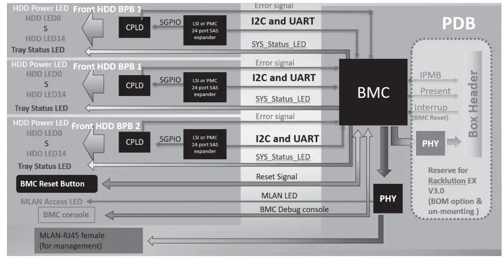
1-3 System Block Diagram
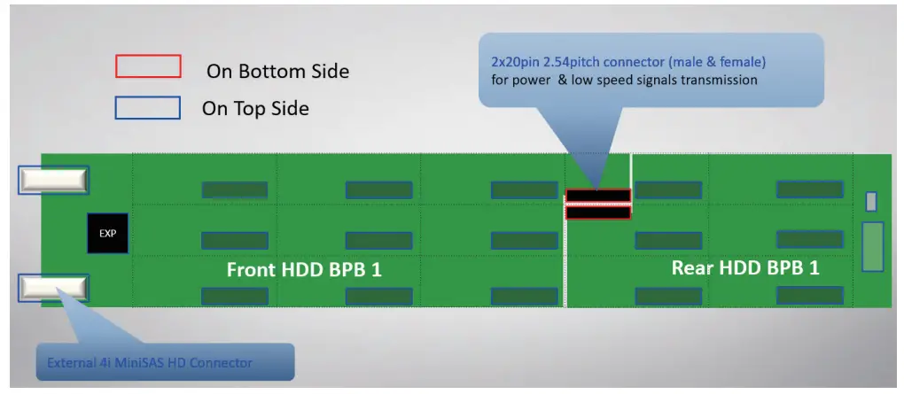
1-4 System Front and Rear HDD Backplane Board View
Chapter 2 Storage System Appearance
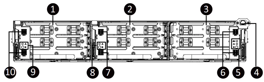
2-1 Front View
| No. | Description |
| 1 | Node1 |
| 2 | Node2 |
| 3 | Node3 |
| 4 | Server Management LAN Port |
| 5 | Node 3 Front Panel LEDs and buttons |
| 6 | miniSAS Hard Disk Drive Connectors #5 / #6 |
| 7 | Node 2 Front Panel LEDs and buttons |
| 8 | miniSAS Hard Disk Drive Connectors #3 / #4 |
| 9 | Node 1 Front Panel LEDs and buttons |
| 10 | miniSAS Hard Disk Drive Connectors #1 / #2 |
 Please go to Front Panel LED and Buttons on page 15 for detail description of function LEDs.
- Please go to System Management LAN LEDs on page 17 for detail description of LAN LEDs.
2-2 Top View
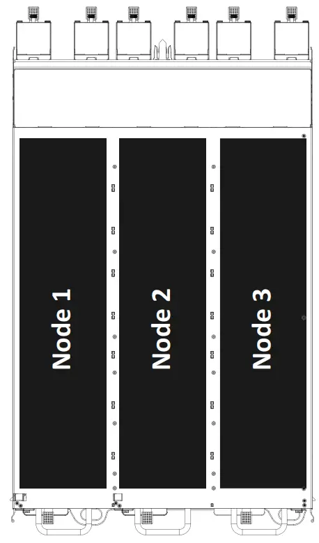
2-3 Rear View
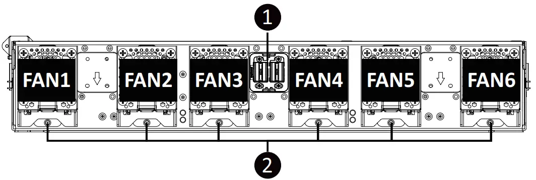
| No. 1. | Description |
| 1 | System Fan Cage |
| 2 | 12V BusBar Power Connector |
2-4 Front Panel LED and Buttons
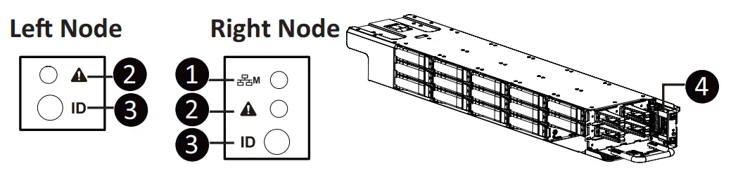
| No | Name | Color | Status | Description |
| 1 | Management LAN Access LED for system (only on the node-3 for whole system) | Green | On | Link between system and network or no access |
| Blink | Data transmission or receiving is occurring | |||
| 2 | Node_# Status LED | Green | On | Indicates HDD operates normally. |
| Amber | On | Indicates HDD failure (more than one HDD failure) or BMC error. | ||
| 3 | ID Button | Blue | On | Indicates the system identification is active. |
| 4 | BMC Reset Button (only on the node-3 for whole system) | — | — | Press this button to reset the system. |
2-5 Hard Disk Drive LEDs
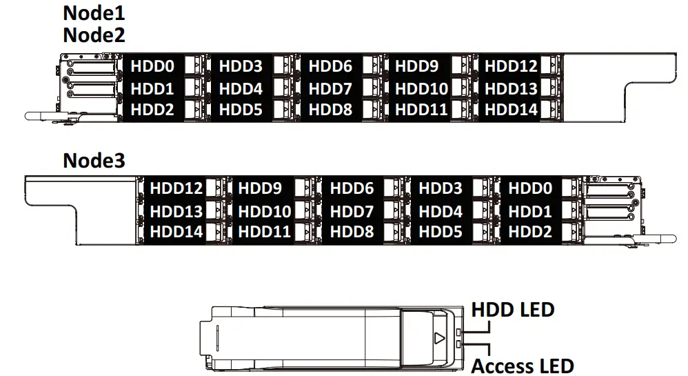
Access LED 1-15
| Color | HDD Present | No HDD |
| Green | ON | OFF |
HDD LED 1-15
| RAID WU | Color | Locate | HDD Fault | Rebuilding | HDD Access | HDD Present (No Access) | |
| No RAID configuration | Disk LED | Green | ON(‘1) | OFF | BLINK (*2) | OFF | |
| Amber | OFF | OFF | OFF | OFF | |||
| Removed HDD Slot | Green | ON(•1) | OFF | _ | |||
| Amber | OFF | OFF | _ | ||||
| RAID configuration | Disk LED | Green | ON | OFF | (Alternatively) | BLINK (“2) | OFF |
| Amber | OFF | ON | (Low Speed: 2 Hz) | OFF | OFF | ||
| Removed HDD Slot | Green | °N(‘1) | OFF | (‘3) | – | ||
| Amber | OFF | ON(‘) | (‘3) | — | |||
Each HDD has one dual color (Green/Amber) LED on HDD Back plane board to show HDD status , its behavior follow the table.
NOTE:
*1: Depends on HBA/Utility Spec.
*2: Blink cycle depends on HDD’s activity signal.
*3: If HDD is pulled out during rebuilding, the disk status of this HDD is regarded as faulty.
2-6 System Management LAN LED
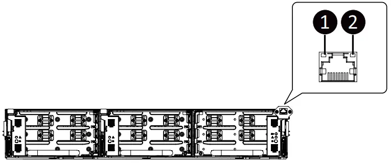
| No. | Name | Color | Status | Description |
| 1 | Speed | Amber | On | 1Gbps data rate |
| Green | On | 100Mbps data rate | ||
| 2 | Link/Act | Green | On | Link between system and network or no access |
| Blinking | Data transmissionor receiving is occuring | |||
| N/A | Off | No data transmission or receiving is occuring |
Chapter 3 Storage System Hardware Installation
![]() Pre-installation Instructions
Pre-installation Instructions
Computer components and electronic circuit boards can be damaged by discharges of static electricity. Working on computers that are still connected to a power supply can be extremely dangerous. Follow the simple guidelines below to avoid damage to your computer or injury to yourself.
- Always disconnect the computer from the power outlet whenever you are working inside the computer case.
- If possible, wear a grounded wrist strap when you are working inside the computer case. Alternatively, discharge any static electricity by touching the bare metal system of the computer case, or the bare metal body of any other grounded appliance.
- Hold electronic circuit boards by the edges only. Do not touch the components on the board unless it is necessary to do so. Do not flex or stress the circuit board.
- Leave all components inside the static-proof packaging until you are ready to use the component for the installation.
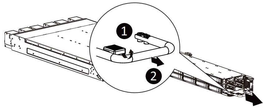
3-1 Removing the Storage System from the Cabinet
Follow these instructions to remove the storage system from the cabinet:
- Press the release latches inward while simultaneously pulling the handle for the system.
- Pull the system out of the cabinet.
- To install the system, push the system back into the cabinet.
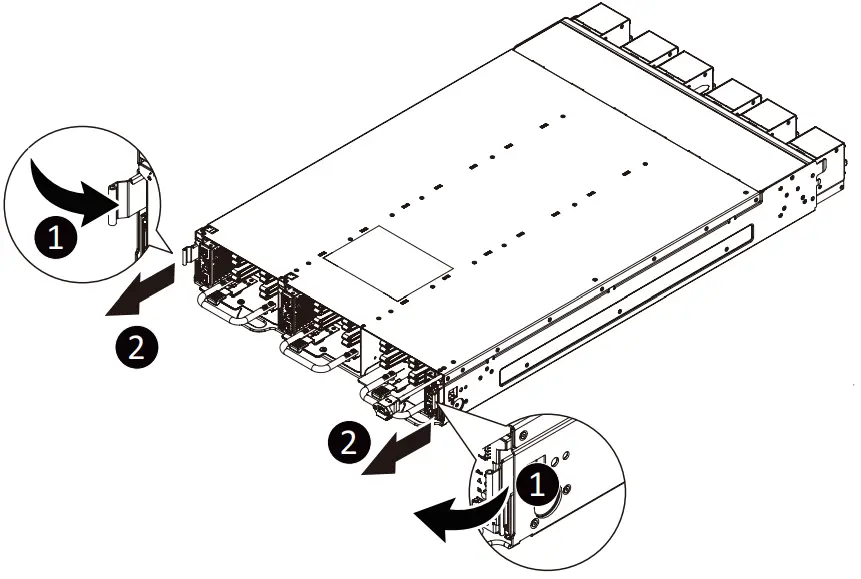
3-2 Removing the Storage Node from the System
Follow these instructions to remove the storage from the system:
- Press the release latch upward while simultaneously pulling the handle for the node.
- Pull the node out of the system.
- To install the node, push the node back into the system.
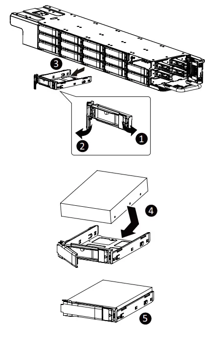
3-3 Installing the Hard Disk Drive![]() Read the following guidelines before you begin to install the Hard disk drive:
Read the following guidelines before you begin to install the Hard disk drive:
- Take note of the drive tray orientation before sliding it out.
- The tray will not fit back into the bay if inserted incorrectly.
- Make sure that the HDD is connected to the HDD connector on the backplane.
Follow these instructions to install a hard disk drive into the front section of the system:
- Press the release button.
- Extend the locking lever.
- Pull the locking lever in the direction indicated to remove the 3.5″ HDD tray.
- Pull the sides of the HDD tray in the direction indicated.
- Slide the hard disk drive into the HDD tray.
- Push the sides of the HDD tray back in the direction indicated to secure the hard disk drive in place.
- Reinsert the HDD tray into the slot and close the locking lever.
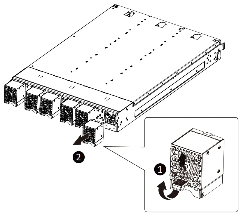
3-4 Replacing the Fan Assembly
Follow these instructions to replace a fan assembly:
- Loosen the thumbscrew on the fan assembly and at the same time pull up the latch.
- Remove the fan assembly from the chassis.
- Reverse the previous steps to install the replacement fan assembly.
![]()


