![]() 4R70E Automatic Transaxle-Transmission
4R70E Automatic Transaxle-Transmission
Instructions Manual
Automatic Transaxle/Transmission — 4R70E/4R75E – Digital Transmission Range (TR) Sensor – in Vehicle Repair
| SECTION 307-01A: Automatic Transaxle/Transmission — 4R70E/4R75E | 2006 E-Series Workshop Manual |
| IN-VEHICLE REPAIR | Procedure revision date: 03/30/2005 |
Digital Transmission Range (TR) Sensor
Special Tool(s)
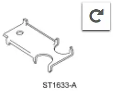 | Alignment Gauge, TR Sensor 307-351 (T97L-70010-A) |
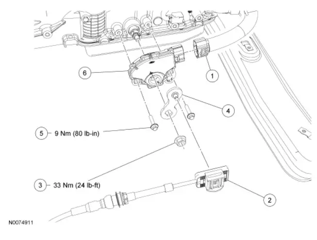
![]()
| Item | Part Number | Description |
| 1 | — | Digital transmission range (TR) sensor electrical connector |
| 2 | 7E395 | Selector lever cable |
| 3 | N808737-S | Manual lever nut |
| 4 | 7A256 | Manual lever |
| 5 | N806933-S | Digital TR sensor bolts |
| 6 | 7F293 | Digital TR sensor |
Removal
- With the vehicle in NEUTRAL, position it on a hoist. For additional information, refer to Section 100-02.
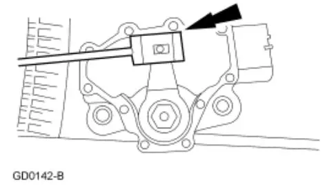
- Disconnect the digital transmission range (TR) sensor electrical connector.
- Disconnect the selector lever cable from the manual control lever.

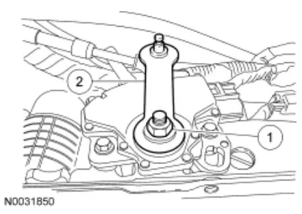
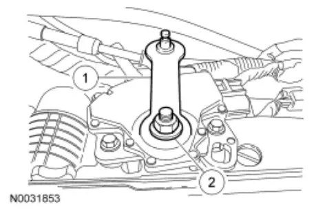
- Remove the manual control lever.
1. Remove the manual control lever outer nut.
2. Remove the manual control lever.
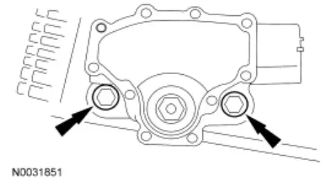
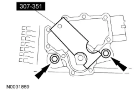
- Remove the digital TR sensor bolts and sensor.

Installation
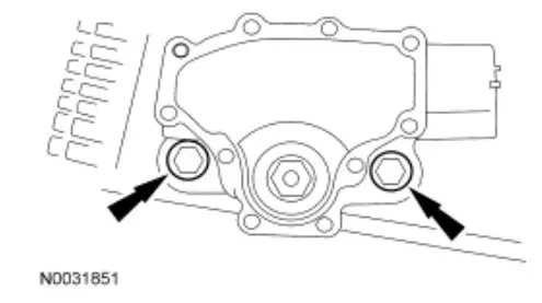
- Loosely install the digital TR sensor bolts and sensor.

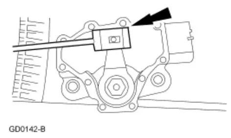
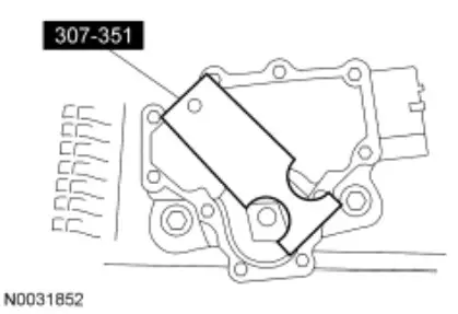
- NOTE: The manual shift lever must be in the NEUTRAL position.
Using the special tool, align the digital TR sensor slots. The tool is designed to fit snug.
- CAUTION: Tightening one screw before tightening the other may cause the digital TR sensor to bind or become damaged.
Tighten the digital TR sensor bolts.
• Tighten to 9 Nm (80 lb-in).
- Install the manual control lever.
1. Position the manual control lever.
2. Install a new manual control lever outer nut.
• Tighten to 33 Nm (24 lb-ft).
- Connect the selector lever cable end to the manual control lever with the manual control lever in the NEUTRAL position.

- Install the digital TR sensor electrical connector.
![]()


