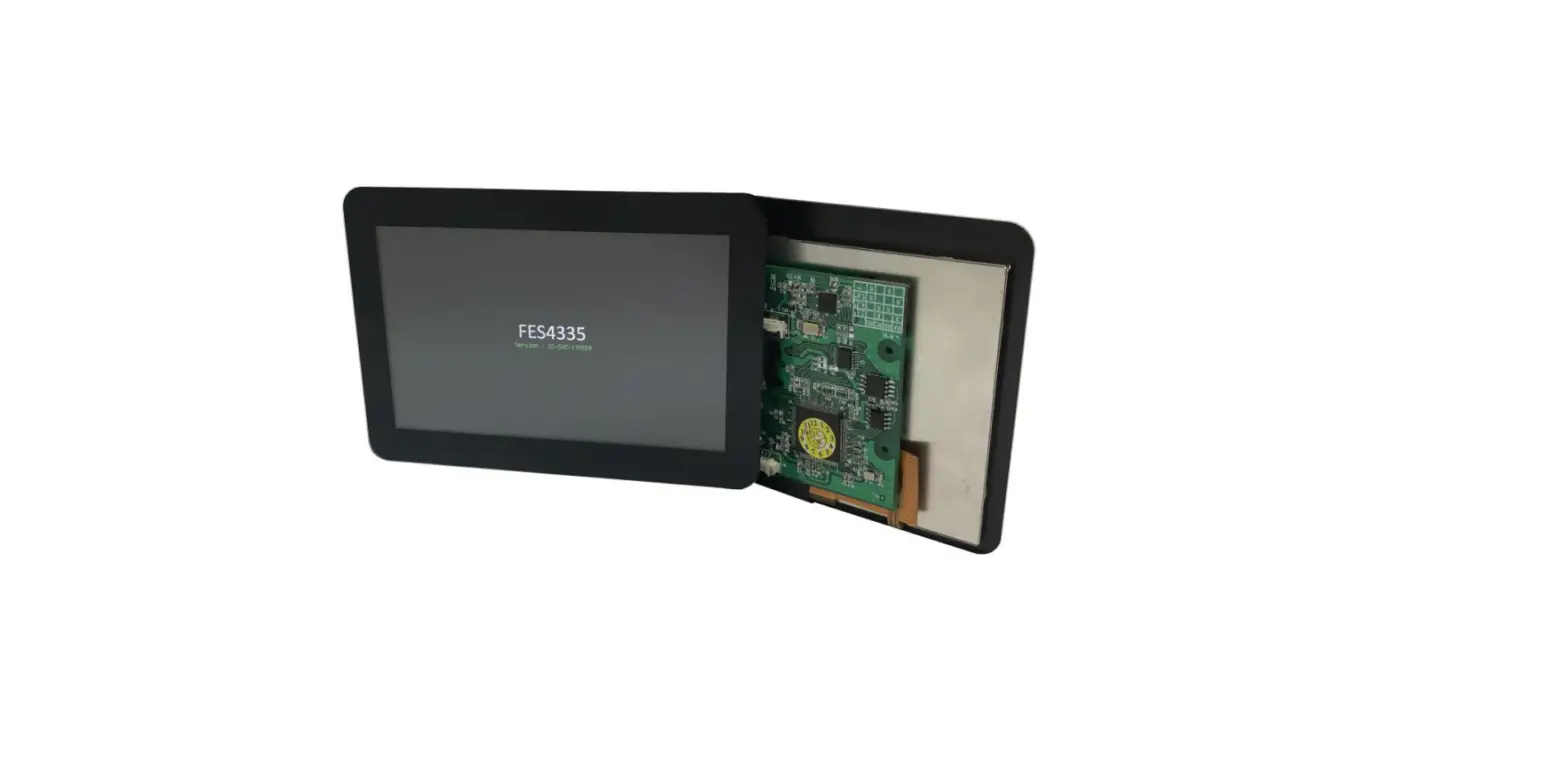
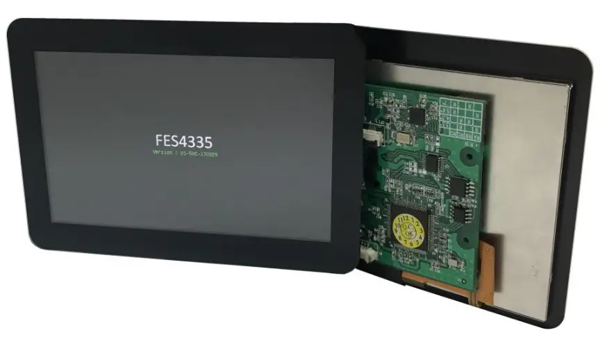
FORENEX FES4335U1 Graphics Control Module
Revision histories
| Rev. No. | Date | Substantial Changes |
| 1.0 | 2017/01 | First issue. |
| 1.1 | 2022/02 | 1. Update communication option 1/2/3 |
| 2. Showing FR-DCE and FR-E2S board |
General Description
- FES4335U1-50C is a low cost, high efficiency and smart of TFT-LCD display control module which can provide characters or 2D graphics application within an embedded 768KB of display RAM.
- FES4335U1-50C offers serial interface (UART-TTL) to establish a hardware communication with an external simple MCU (as like 8051 etc.), and providing the “Commands Table” for graphical effect calling and execution.
- According to the “Commands Table” of graphics APIs, the external MCU only need to transmit the corresponding command code with parameters into FES4335U1-50C over serial interface. The command decoder inside of FES4335U1-50C would go to implement the graphics task by automatically.
| Item | Specification | Remark |
| LCD size | 5.0 (Diagonal) | inch |
| Resolution | 800 x 3(RGB) x 480 | dot |
| Color arrangement | 18bit colors (RGB- Vertical Stripe) | |
| Display type | Normally White. Transmissive type | |
| Active area | 108.0(W) x 64.8(H) | mm |
| Module size | 131.0(W) x 90.5(H) x 12.6(D) | mm |
| View angle | L:60/ R:60/ T:60/ B:60 | θ |
| Contrast ratio | Typ. 600 @ (θ=0°) | CR |
| Backlight type | Build-in LED driver | |
| Brightness(Luminance) | Typ. 850 | cd/m² |
| Touch type | PCAP | |
| Interface | UART, 115200/ N/ 8/ 1 | |
| Software offer | Forenex’s Free editing tool | Note1 |
| Images FlashROM | (Typ.)8MB/16MB | |
| FlashROM for images storage | 7 pages (8MB)/ 14 pages (16MB) | |
| Picture switching speed | About 100ms/frame | |
| Picture downloading | FG875D_Command_Encoder.exe | |
| Operation Temp | -20℃ to 70℃ | |
| Storage Temp | -30℃ to 80℃ |
Note1: The Forenex’s Free editing tool that (FG875D_Command_Encoder.exe) is a windows app. In the utility, all of usable APIs that summarized in command Table can be selected and auto-encoding. Refer to document (FG875D_Commands Table_vx.pdf) and (FG4335x_software_Note_V1.pdf) for detail usage description for each command.
Pin Assignment
UART Input interface (W1)
| Connector on board (W1): Wafer_4pin/ 1.25mm/ side entry | |||
| Connector Matching Suggest: Molex 51021 or compliant | |||
| Pin num | Description | I/O | Note |
| Pin1 | VCC | DC5V | |
| Pin2 | TX | O | |
| Pin3 | RX | I | |
| Pin4 | GND | ||
GPIO interface (W3)
| Connector on board (W3): Wafer_4pin/ 1.25mm/ side entry | |||
| Connector Matching Suggest: Molex 51021 or compliant | |||
| Pin num | Description | I/O | Note |
| Pin1 | GPI 0 | I | 2 |
| Pin2 | GPI 1 | I | 2 |
| Pin3 | GPI 2 | I | 2 |
| Pin4 | GPI 3 | I | 2 |
| Pin5 | GPO 0 | O | 3 |
| Pin6 | GPO 1 | O | 3 |
| Pin7 | GPO 2 | O | 3 |
| Pin8 | GPO 3 | O | 3 |
| Pin9 | GND | ||
- NOTE2: The GPO_0 ~ 3 are output with a series resister 100 Ohm.
- NOTE3: The GPI_0 ~ 3 are 3.3V input with 5V tolerant.
Operation Specifications
Electrical specifications
Absolute Maximum Ratings
| Item | Symbol | Min. | Max. | Unit | Note |
| Power Voltage | VCC | -0.3 | 5.2 | V | |
| Operating Temperature | TOP | -20 | 70 | ℃ | |
| Storage Temperature | TST | -30 | 80 | ℃ |
The absolute maximum rating values of this product are not allowed to be exceeded at any time.
Recommended operating condition
| Symbol | Description | Min. | Typ. | Max. | Unit | Note |
| VCC | Supply voltage | 4.75 | 5 | 5.25 | V | |
| I(VCC) | Supply Current | – | 640 | 650 | mA | |
| UART-(Tx/Rx),GPIOs signal level | ||||||
| VIH | Input High Voltage | 2 | 3.3 | 5 | V | |
| VIL | Input Low Voltage | -0.3 | – | 0.8 | V | |
| VOH | Output High Voltage | 2.4 | – | – | V | |
| VOL | Output Low Voltage | – | – | 0.4 | V | |
| Ileak | Input Leakage Current | -10 | – | 10 | uA | |
| Optical Specifications (θ=0°) | ||||||
| CR | Contrast Ratio | 500 | 600 | – | ||
| L | Luminance | 700 | 850 | – | cd/m² | |
| Power consumption @ 5V input, Brightness 100% | ||||||
| Consumption | 5.0” , 800×480 | 3.25 | W | |||
Mechanical specification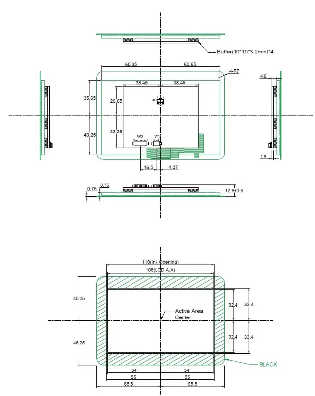
Hardware specification
Block Diagram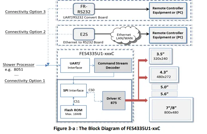
Serial communication option (1/2/3)
Baud Rate: be fixed at 115200 bps/N/8/1.
Option 1: By 3-wire UART (TX, RX, GND).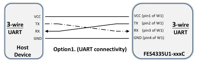
Option2: By RS232 with an external board FR-DCE (UART to RS232 converter)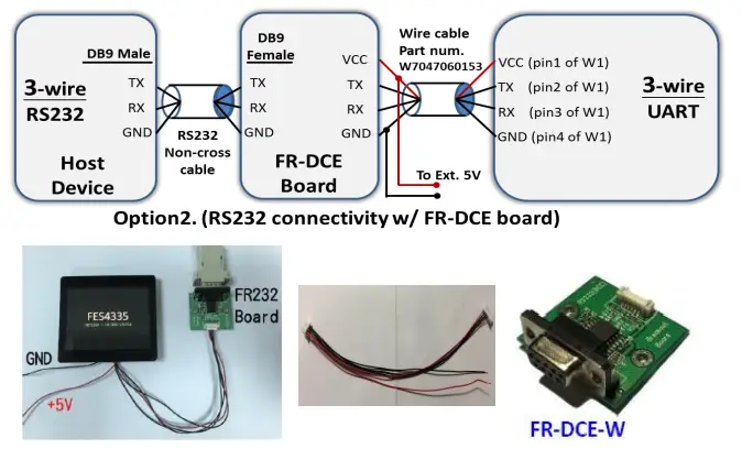
Option3: By Ethernet with an external board FR-E2S (UART to Ethernet converter)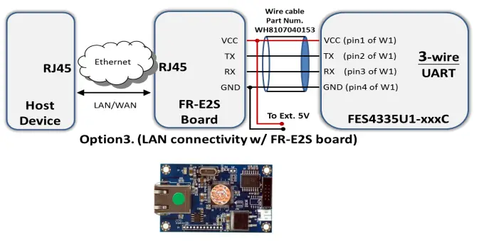
Software
Communication (handshaking)
- Due to the serial interfaces (UART), the FES4335U1 series have offered to establish communication with an external host.
- The host is able to transmit a command stream to FES4335U1 for a task implementation asking.
- According to the capacity of transmission, the command stream format is simply defined into two categories.
- Standard Command Stream: This is an essential command stream format for each one task which is listed in the Commands Table. (Refer to FG875D_Commands Table_vx.pdf).
- Bulk Data Transmission Stream: Only provide to some tasks will ask for a bulk data transmission, and the asking has confirmed during the standard command stream stage.
- Currently only below two tasks which will ask for a Bulk Data Transmission protocol.
- FG875D_WriteToSerialROM (function code 0x21).
- FG875D_Display_Block_RW (function code 0x24).
- According to the Commands Table, each command has a unique function code for a specific operation task.
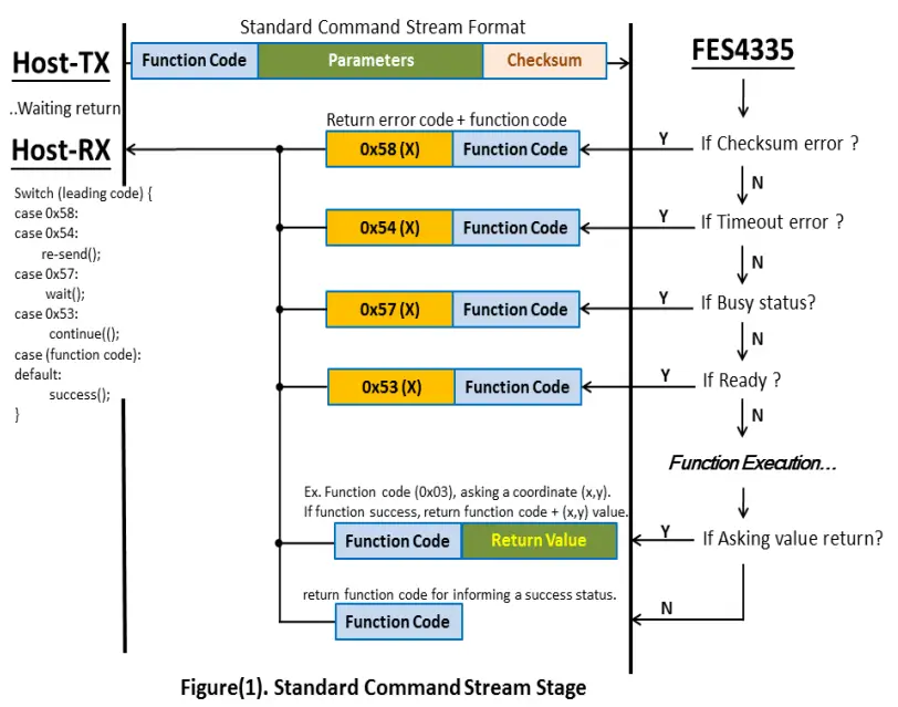
- Therefore, once the FES4335U1 has received a complete of Standard Command Stream and which part of checksum is checked firstly. After that, the part of function code would be identified and implemented along with parameters part.
- There are a specifically code area 0x50~0x5F where will dedicate to define some message code and also be isolated from the all of function code.
| Return message code | ASCII | hex | Description |
| Wrong code | “X” | 0x58 | Checksum error |
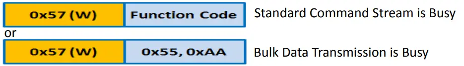
| Waiting code | “W” | 0x57 | FES4335 is busy |
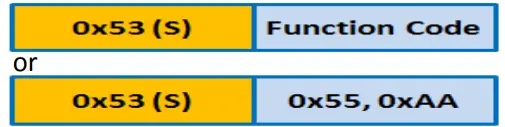
| Ready code | “S” | 0x53 | FES4335 is ready |
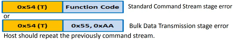
| Timeout code | “T” | 0x54 | Receive Timeout |
| Touch Interrupt code | “P” | 0x50 | Touch panel has been touched |
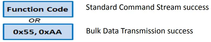
| Command success code | Function code | Command implement success | |
| Bulk transmission success code | 0x55,0xAA | Bulk data transmission success | |
If there is no error encountered during transmission.
- The FES4335U1 will implement command according to function code that has received in Standard Command Stream Stage, and return function code to Host for success checking. or
- Return function code (0x55,0xAA) to indicate this time of Bulk Data Transmission has completed without problem in “Bulk Data Transmission stage”.
- Return Success code or (0x55,0xAA), informing a success status.

- Host could send next new command stream.
- If there is any unexpected condition has encountered during transmission.
- The FES4335 will return a corresponding error code message and along with the received function code for error checking.
- If return Wrong code (0x58) like below. (indicate a Checksum error has occurred)
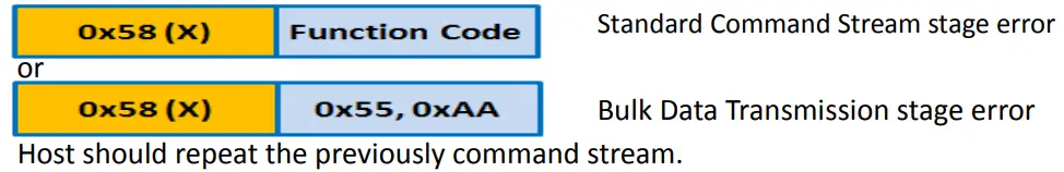
- If return Timeout code (0x54) like below, (indicate a Timeout error has occurred)

- Return Wait code (0x57) like below, (indicate a wait status has occurred)

- To inform host that FES4335U1 is in a busy status.
Host should temporary stop transmission until FES4335U1 return Ready code (0x53) and then continue the command stream or bulk data stream those do not finish data yet. - Return Ready code (0x53) like below, (indicate a ready message has occurred)

- Standard Command Stream is Ready
- Bulk Data Transmission is Ready
- To inform host that FES4335U1 has released from the period of busy status.
- The Host can continue the rest of command stream or bulk data stream.
- A specific code to inform the touch interrupt has occurred and also would return the coordinate (x,y) value of touch panel automatically.
- Return Touch interrupt code (0x50) with coordinate (x,y) value like below,

- a. In a bulk data transmission stage, the FES4335U1 will temporary to disable touch function and stop return the coordinate (x,y) of touch.
- b. Out of a bulk data transmission stage. FES4335U1 would automatically return the coordinate (x,y) of touch when a touch interrupt has occurred.
- c. Host could also to poll the coordinate (x,y) value by sending Function code 0x03 (APIs:FG875D_Detect_Touch).

Command (Stream /Format /protocol)
Standard Command Stream
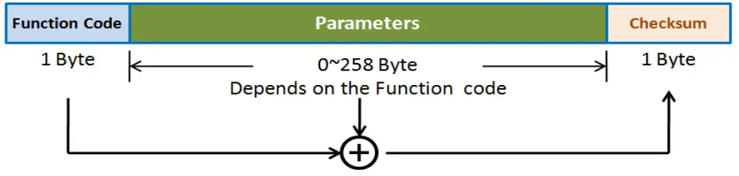
- Format: This format combines a byte of function code and several parameter bytes and a byte of checksum code.

- Protocol:

Bulk Data Transmission
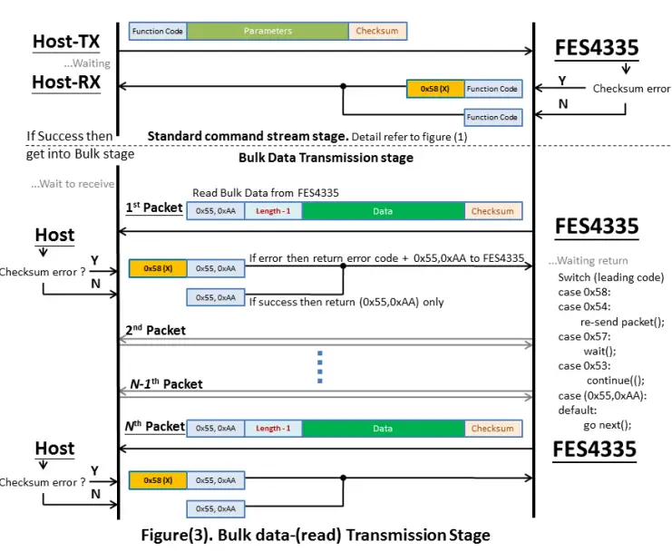
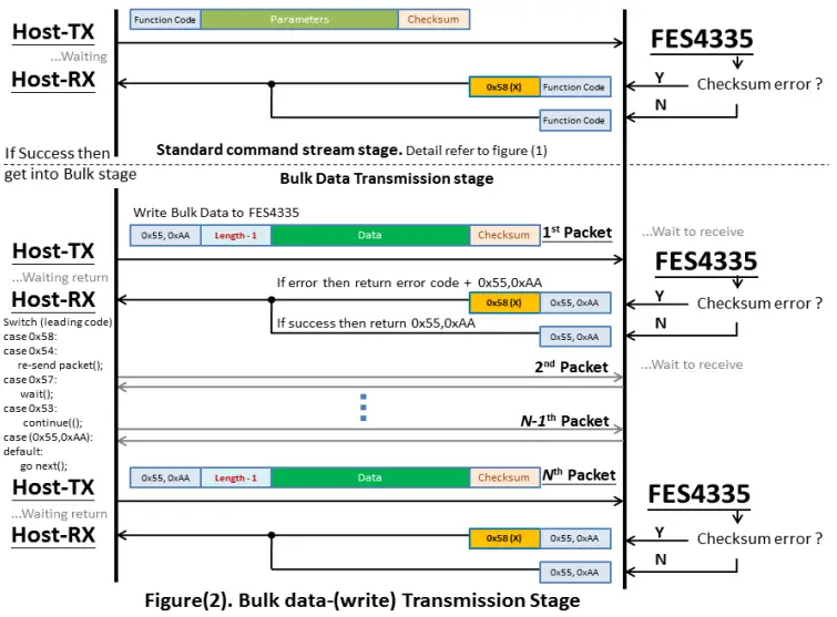
- Since the function code in Standard Command Stream is (0x21) or (0x24) that will ask a bulk data transmission task after those function code have be identified by FES4335U1. In this case, the whole communication process will be separated into two stages (Standard Command Stream stage + Bulk Data Transmission protocol stage).
- Format: This format is available for bulk data transmission stage only.
- The leading code (0x55,0xAA) will replace function code to indicate a Bulk Data Transmission beginning and then the value be set into length byte is indicated how many data byte will comes up in continuously. Notice to set length byte with real data quantity minus 1.

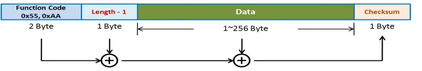
Protocol:
- The illustration to show the standard command stream which ask to write a bulk data transmission to FES4335U1.

- The illustration shows the standard command stream which asks to read a bulk data transmission from FES4335U1.
Appendix (Tips)
- Three steps to show still images on screen more quickly.
- Step1): Converting image to a .bin file:
- Due to the FES4335U1’s Flash-ROM only accepts the (.bin) file of the image. Therefore, firstly use the utility FES87x_Image_Tool.exe that is able to convert the (.BMP/.JPG) file into (.BIN) file. Refer to document〝FES87x_Image_Tool_User_Guide_v1.0.pdf〞for for detail.
- Step 2): Loading .bin file to the internal SPI-FlashROM(AMIC A25LQ64).
- Using the function code 0x21 (APIs:FG875D_WriteToSerialROM) to require FES4335U1 to go into the bulk data transmission stage.
- After the Command success code(0x21) is returned from FES4335U1, then external MPU be allowed to transmit images according to the protocol description about the bulk data-(write) transmission on section 4-2-2. Refer to figure (2).
- Another way to skip ① & ②:
On PC side, to execute utility software (FG875D_command_encoder.exe) that is a useful free tool from Forenex. and choose function item (FG875D_WriteToSerialROM) in selection dialog. After then, the utility software will take care all about communication protocol and uploading image file into SPI-FlashROM.
- Regarding to the usage of utility software (FG875D_command_encoder.exe), please refer to document “FG875D_Command_Encoder-UsersMenu.pdf”.
- Step3): Using the function code 0x22 (APIs: FG875D_DisplayIMG_FromSerialROM) to require FES4335 to display images from internal SPI_FlashROM to an indicated location of panel.


 Led Driving Board Owner's Manual")


