![]() FT2003-U1
FT2003-U1
Graphic driver (I/O)
Installation
Mounting
Smart Infrastructure
Instruction Manual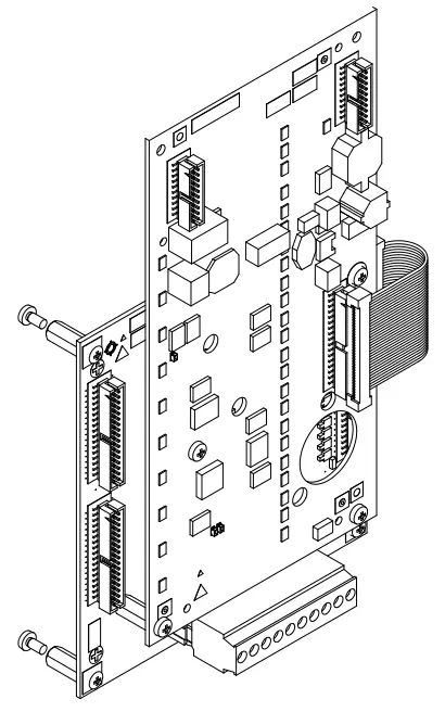
FT2003-U1 Graphic I-O Driver
Legal notice
Technical specifications and availability subject to change without notice.
Transmittal, reproduction, dissemination and/or editing of this document as well as utilization of its contents and communication thereof to others without express authorization are prohibited. Offenders will be held liable for payment of damages. All rights created by patent grant or registration of a utility model or design patent are reserved.
Issued by:
Siemens Industry, Inc.
Smart Infrastructure
8 Fernwood Road
Florham Park, NJ 07932
Tel. +1 973-593-2600
www.sbt.siemens.com/FIS
Edition: 2019-11-25
Document ID: A6V10384377_b_en_-A5Q00054475
© Siemens Industry, Inc., 2012
Graphic driver (I/O) FT2003
1.1 Description
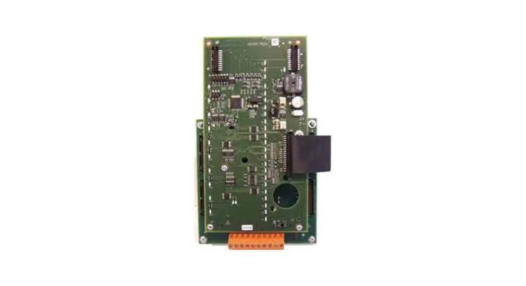
The graphic driver (I/O) FT2003-U1 is a remote display and operating unit that is supplied without an housing or display panel. It consists of the FTI2002 connection PCB and the FTO2007 operation, which are screwed together. Four spacer bolts enable it to be installed in a housing (1HU). The graphic driver (I/O) is supplied via the system supply of the associated panel.
Properties
- Communication interface via the RS485 module class A to the fire control panel
- A maximum of 8 graphic drivers (I/O) can be connected to one RS485 circuit
- Supply inputs for a 24 V supply
- Connections for 34 external LED mimic display indicators
- Connections for 16 external mimic display buttons
- Connection for an external key switch
1.2 Installation
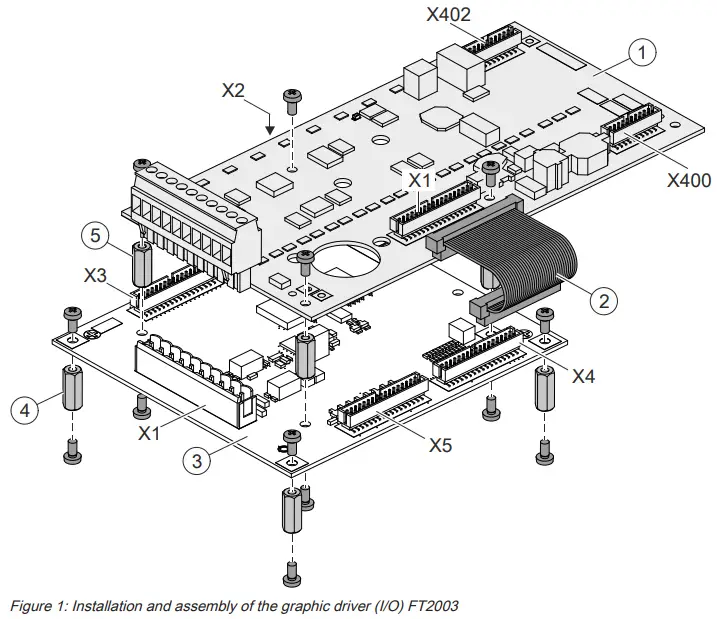
| 1 | Printed circuit board for FTO2007 operation |
| 2 | Ribbon cable of FTI2002 connection PCB for FTO2007 operation |
| 3 | FTI2002 connection PCB |
| 4 | 4 spacer bolts, 15 mm, and fixing screws for securing the housing |
| 5 | 4 spacer bolts, 15 mm, and fixing screws for securing the printed circuit board |
| X1 | FTO2007 operation: connection to X4, connection PCB FTI2002 |
| X1 | FTI2002 connection PCB: terminal strip for supply and RS485 circuit |
| X2 | LED mimic display indicator connections 1…17 |
| X3 | LED mimic display indicator connections 18…34 |
| X4 | Connection to X1, FTO2007 operation |
| X5 | Mimic display operation connections |
| X400 | Connection of peripheral data bus output to further graphic drivers (I/O) |
| X402 | Connection of peripheral data bus input from further graphic drivers (I/O) |
Preparation
The FT2003-U1 graphic driver (I/O) is supplied as a component that the operator installs in a 1HU housing. The power supply must be provided via the system supply of an FC20xx or FT2050 panel.
The following components are also required to operate the graphic driver (I/O):
- Housing (1HU)
- Front panel, LED indicators, operating buttons, and optional key switch for the mimic display panel
- Power supply via the system supply of an FC20xx or FT2050 panel
- Molex 87586-3493 multipoint connectors (Siemens no. A5Q00005805) for mimic display connections
- Ribbon cable, 34 pin x 1 m, for mimic display connections
- RS485 module class A FCA2016 for connection to the control panel Mounting
- Using the 4 spacer bolts and the fixing screws (4), install the assembled FT2003 graphic driver (I/O) in the housing.
- Install the power supply and the mimic display elements according to the pin assignments listed below.
1.3 Views
1.3.1 FTI2002 connection PCB view
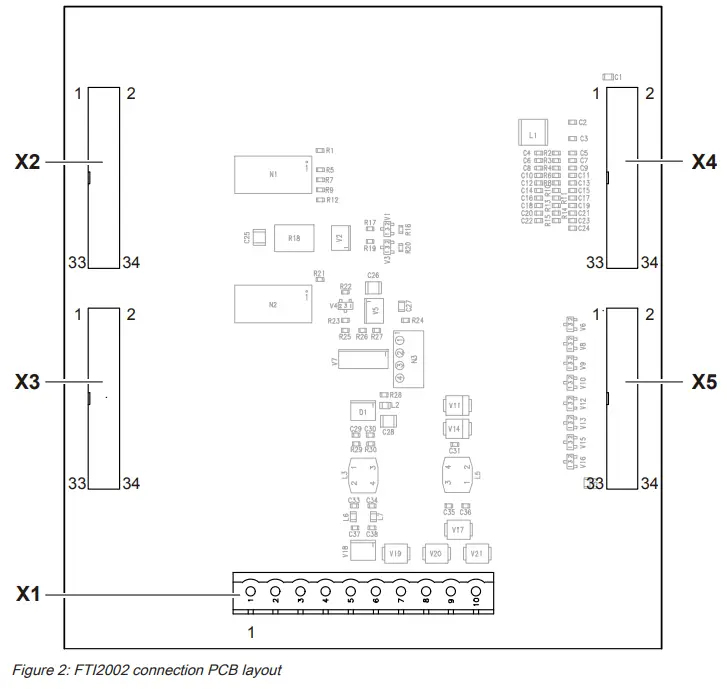
| Element | Des. | Function |
| Plugs and terminals | X1 | Supply and RS485 connection |
| X2 | LED mimic display indicator connections 1…17 | |
| X3 | LED mimic display indicator connections 18…34 | |
| X4 | Connection to FTO2007 operation | |
| X5 | Mimic display operation (16x) and optional key switch |
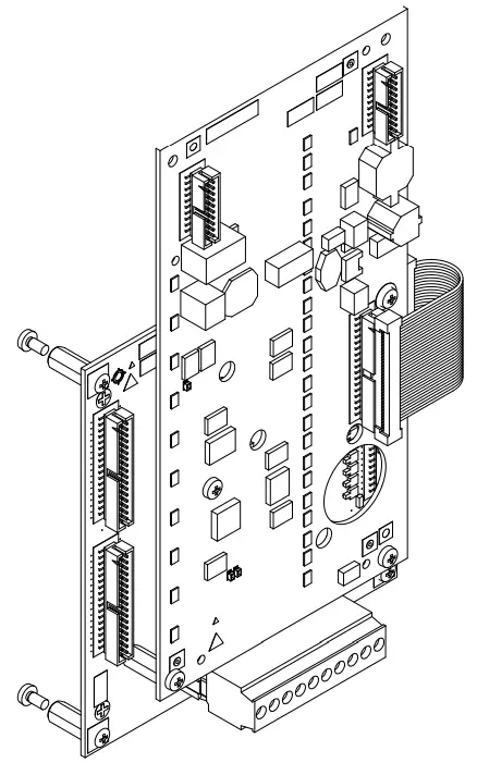
1.3.2 FTO2007 operation view
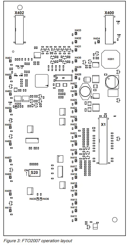
| X400 | Connection of peripheral data bus output to further graphic drivers (I/O) |
| X402 | Connection of peripheral data bus input from further graphic drivers (I/O) |
| H401…H434 | Not used (corresponding ‘HWLED’ LEDs on connector board X2 and X3) |
| H205 | Watchdog |
| H201 | Buzzer |
| S20 (1…6) | DIP switch for configuration |
| X1 | Connecting plug for connector board FTI2002 |
1.4 Wiring
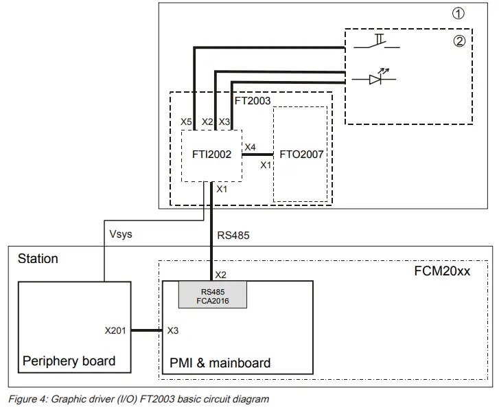
| 1 | Remote LED alarm indicator in housing (1HU) |
| 2 | LED mimic display panel (LED connections and external buttons) |
| FTI2002 | Connection PCB |
| FTO2007 | Operation |
| FT2003 | Graphic driver (I/O) |
The graphic driver (I/O) is operated as a remote mimic display indicator at a distance of up to 3280 ft/1000 m from the panel. The FT2003 graphic driver (I/O) consists of an FTI2002 connection PCB and an FTO2007 operation, but has no indicator panel.
The graphic driver (I/O) is installed in a housing (1HU). The associated LED indicators are arranged according to the layout plan. It is connected to the RS485 class A module on the PMI & mainboard of the ‘Panel’. It is supplied via an FC20xx or FT2050 ‘Panel’.
Graphic driver (I/O) FT2003 wiring diagram
A maximum of 8 FT2003 graphic drivers (I/O) can be connected to the RS485 circuit.
It is possible to use either a class A or a class B circuit. You will find detailed information about the RS485 circuit in the description of the FCA2016 RS485 class A module (isolated).
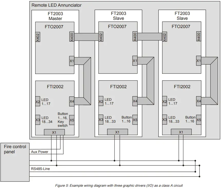
| X1 | FTI2002 connection PCB: Supply and RS485 circuit connection |
| X1 | FTO2007 operation: connection of X4 connection PCB |
| X2 | LED mimic display connection 1…17 |
| X3 | LED mimic display connection 18…34 with master or 18…33 with slave |
| X4 | Connection to X1 of the FTO2007 operation |
| X5 | Mimic display connection key 1…16, key switch |
| X400 | Peripheral data bus output to the following graphic driver (I/O) |
| X402 | Peripheral data bus input from the preceding graphic driver (I/O) |
1.5 FTI2002 connection PCB pin assignments
1.5.1 X1 supply and circuit connection
| Pin | Designation | Description |
| 10 | VSYS- | Supply input from the power supply (-) |
| 9 | VSYS- | Supply input from the power supply (-) |
| 8 | VSYS+ | Supply input from the power supply (+) |
| 7 | VSYS+ | Supply input from the power supply (+) |
| 6 | RS485 B | Input connection B |
| 5 | RS485 A | Input connection A |
| 4 | COMMON | GND |
| 3 | Not used | |
| 2 | Not used | |
| 1 | Not used |
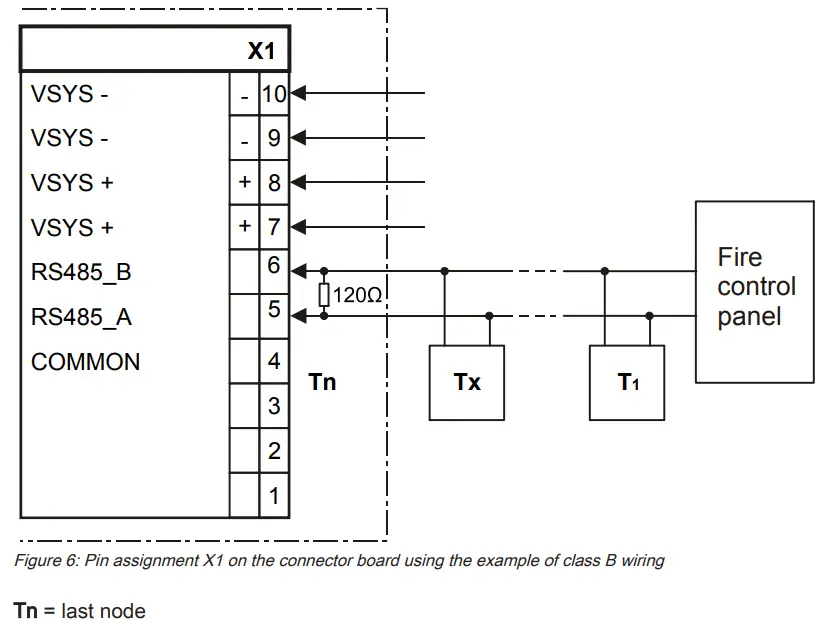
| NOTICE | |
| Observe polarity for connections A and B. The last participant connection must have a resistance of 120 Ω. |
![]() The FT2003 graphic driver (I/O) is connected to the FCA2016 RS485 class A module (isolated). Please note that the graphic driver (I/O) has a fixed baud rate of 9600 kbit/s and can only be operated together with the FT2014 remote display and FT2015 remote terminal all on the same circuit if these two devices are set to the same baud rate. No other combinations are possible.
The FT2003 graphic driver (I/O) is connected to the FCA2016 RS485 class A module (isolated). Please note that the graphic driver (I/O) has a fixed baud rate of 9600 kbit/s and can only be operated together with the FT2014 remote display and FT2015 remote terminal all on the same circuit if these two devices are set to the same baud rate. No other combinations are possible.
Baud rates are specified in the documentation for the corresponding components.
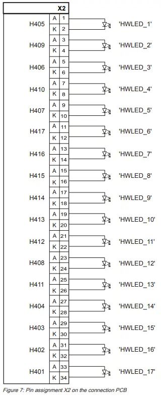
1.5.2 X2 LEDs, mimic display indicator
| Pin | Connection for LED | LED ID in configuration |
| 1, 2 | H405 (green) | HWLED_1 |
| 3, 4 | H409 (green) | HWLED_2 |
| 5, 6 | H406 (green) | HWLED_3 |
| 7, 8 | H410 (green) | HWLED_4 |
| 9, 10 | H407 (green) | HWLED_5 |
| 11, 12 | H417 (yellow) | HWLED_6 |
| 13, 14 | H416 (red) | HWLED_7 |
| 15, 16 | H415 (yellow) | HWLED_8 |
| 17, 18 | H414 (red) | HWLED_9 |
| 19, 20 | H413 (yellow) | HWLED_10 |
| 21, 22 | H412 (red) | HWLED_11 |
| 23, 24 | H408 (green) | HWLED_12 |
| 25, 26 | H411 (yellow) | HWLED_13 |
| 27, 28 | H404 (green) | HWLED_14 |
| 29, 30 | H403 (green) | HWLED_15 |
| 31, 32 | H402 (green) | HWLED_16 |
| 33, 34 | H401 (green) | HWLED_17 |
1.5.3 X3 LEDs, mimic display indicator
| Pin | LED connection | LED ID in configuration |
| 1, 2 | H422 (red) | HWLED_18 |
| 3, 4 | H426 (red) | HWLED_19 |
| 5, 6 | H423 (yellow) | HWLED_20 |
| 7, 8 | H427 (yellow) | HWLED_21 |
| 9, 10 | H424 (red) | HWLED_22 |
| 11, 12 | H434 (red) | HWLED_23 |
| 13, 14 | H433 (green) | HWLED_24, operating indicator (master) |
| 15, 16 | H432 (yellow) | HWLED_25 |
| 17, 18 | H431 (yellow) | HWLED _ 26, connection error |
| 19, 20 | H430 (red) | HWLED_27 |
| 21, 22 | H429 (yellow) | HWLED_28 |
| 23, 24 | H425 (yellow) | HWLED_29 |
| 25, 26 | H428 (red) | HWLED_30 |
| 27, 28 | H421 (yellow) | HWLED_31 |
| 29, 30 | H420 (red) | HWLED_32 |
| 31, 32 | H419 (yellow) | HWLED_33 |
| 33, 34 | H418 (red) | HWLED_34 |
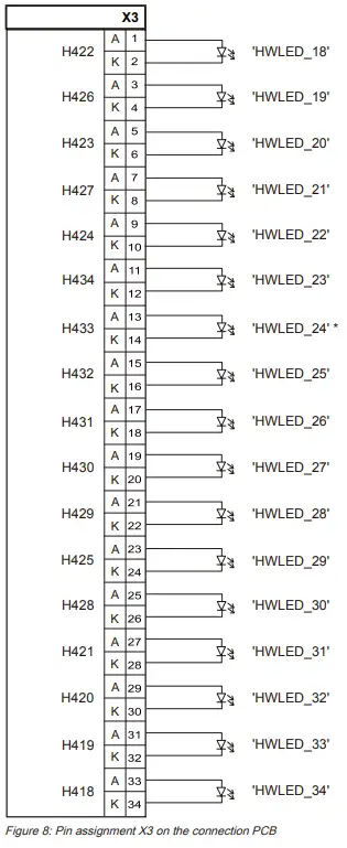 * Only used with master graphic driver (I/O)
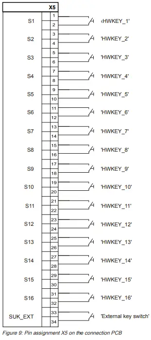
1.5.4 X5 mimic display operation
| Pin | Connection key | Key ID in configuration |
| 1, 2 | S1 | HWKEY_1 |
| 3, 4 | S2 | HWKEY_2 |
| 5, 6 | S3 | HWKEY_3 |
| 7, 8 | S4 | HWKEY_4 |
| 9, 10 | S5 | HWKEY_5 |
| 11, 12 | S6 | HWKEY_6 |
| 13, 14 | S7 | HWKEY_7 |
| 15, 16 | S8 | HWKEY_8 |
| 17, 18 | S9 | HWKEY_9 |
| 19, 20 | S10 | HWKEY_10 |
| 21, 22 | S11 | HWKEY_11 |
| 23, 24 | S12 | HWKEY_12 |
| 25, 26 | S13 | HWKEY_13 |
| 27, 28 | S14 | HWKEY_14 |
| 29, 30 | S15 | HWKEY_15 |
| 31, 32 | S16 | HWKEY_16 |
| 33 | SUK_EXT | External key switch |
| 34 | (GND) | GND for external key switch |
1.6 Adjustment elements
The graphic driver (I/O) is configured with the S20 switch on the FTO2007 operation.
![]() Each address can only be issued once per panel.
Each address can only be issued once per panel.
The factory setting is always set for the corresponding application.
Setting for one graphic driver (I/O) or master
| S20 switch | Meaning | |||||
| 1 | 2 | 3 | 4 | 5 | 6 | |
| SO | S1 | S2 | Master | Syn1 | (Empty) | |
| ON | ON | Device address 1 | ||||
| ON | ON | ON | Device address 2 | |||
| ON | ON | ON | Device address 3 | |||
| ON | ON | ON | ON | Device address 4 | ||
| ON | ON | ON | Device address 5 | |||
| ON | ON | ON | ON | Device address 6 | ||
| ON | ON | ON | ON | Device address 7 | ||
| ON | ON | ON | ON | ON | Device address 8 | |
| X | X | X | ON | ON | Mimic display outputs are controlled and queried (LEDs, buttons, and key switches) | |
Empty fields = switch in ‘OFF’ position
X = switch setting according to address 1 to 8
1 The S20/5 (Syn) switch must be set to the ON position with the graphic driver (I/O).
This deactivates the LEDs on the FTO2007 operation.
2 In the case of the first graphic driver (I/O) and for every master, S20/4 (master) must be set to the ON position.
Setting for second graphic driver (I/O) or slave
| S20 switch | Meaning | |||||
| 1 | 2 | 3 | 4 | 5 | 6 | |
| SO | S1 | S2 | Master | Syn | (Empty) | |
| OFF | ON | Device address 1 | ||||
| ON | OFF | ON | Device address 2 | |||
| ON | OFF | ON | Device address 3 | |||
| ON | ON | OFF | ON | Device address 4 | ||
| ON | OFF | ON | Device address 5 | |||
| ON | ON | OFF | ON | Device address 6 | ||
| ON | ON | OFF | ON | Device address 7 | ||
| ON | ON | ON | OFF | ON | Device address 8 | |
| X | X | X | OFF | ON | Mimic display outputs are controlled and queried (LEDs, buttons, and key switches) | |
Empty fields = switch in ‘OFF’ position
X = switch setting according to address 1 to 8
1 The S20/5 (Syn) switch must be set to the ON position with the graphic driver (I/O).
This deactivates the LEDs on the FTO2007 operation.
2 Multiple graphic drivers (I/O) may not be operated at the same address on a panel.
With the second and every additional graphic driver (I/O), the address must be set 1 higher. For slave operation, S20/4 must be set to the OFF position.
1.7 Technical data
| Graphic driver (I/O) FT2003 | ||
| Mechanical data | Dimensions (L x W x H) Weight | 8.11 x 4.76 x 1.97 ” / 206 x 121 x 50 mm 7.05 oz. / 200 g |
| FTI2002 connection PCB | ||
| Supply | Operating voltage Operating current | DC 20…32 V Max. 1 A (21 V) Depending on the configuration |
| LED operating currents | Master indicator Slave indicator | 34 x 13 mA / 3.3 V / 1.5 W 33 x 13 mA/3.3 V/1.4 W |
| Connection terminals | Supply and RS485 connection Design Admissible cable cross-section Inputs and outputs Mimic display connections and peripheral data bus | Screw terminals 0.2…1.5 mm² Plug connection for ribbon cable |
| Mechanical data | Dimensions (L x W x H) Weight | 5.12 x 4.76 x 1.26 ” / 130 x 121 x 32 mm 3.2 oz. / 90 g |
| FTO2007 operation | ||
| Supply input | Voltage Operating current Alarm current | DC 20…32 V 19.5 mA 32 mA |
| Supply output | Voltage Curent | DC 20…32 V Looped, max. 1 A |
| LEDs | Quantity Function | 34 for operating indicator 1 for trouble (watchdog) Can be configured with Desigo Fire Safety Works |
| Connectors | Peripheral data bus (input and output) | Plug connection with ribbon cable |
| Mechanical data | Dimensions (W x H x D) Weight | 7.28 x 3.78 x 0.47 ” / 185 x 96 x 12 mm 2.5 oz. / 70 g |
FCC Statement
 | WARNING |
| Installation and usage of equipment is not in accordance with instructions manual Radiation of radio frequency energy Interference to radio communications ● Install and use equipment in accordance with instructions manual. ● Read the following information. |
This equipment generates, uses, and can radiate radio frequency energy and if not installed and used in accordance with the instructions manual, may cause interference to radio communications.
It has been tested and found to comply with the limits for a Class A computing device pursuant to Part 15 of FCC Rules, which are designed to provide reasonable protection
against such interference when operated in a commercial environment.
Operation of this equipment in a residential area is likely to cause interference in which case the user at his own expense will be required to take whatever measures may be required to correct the interference.
Issued by
Siemens Industry, Inc.
Smart Infrastructure
8 Fernwood Road
Florham Park, NJ 07932
+1 973-593-2600
www.sbt.siemens.com/FIS
© Siemens Industry, Inc., 2012
Technical specifications and availability subject to change without notice.
firealarmresources.com


