![]()
XB-H
Hybrid Ventilation Unit
Installation Manual
 EMC Directive 2014/30/EU
LVD Directive 2014/35/EU
SAFETY INFORMATION
- The provision of the electrical supply and the connection of the unit to the mains must becarried out by a qualified electrician.
- Isolate from power supply before removing any covers. During installation / maintenance ensure all covers are fitted before switching on the mains supply.
- All-pole disconnection from the mains as shown in the wiring diagram must be incorporated within the fixed wiring and shall have a minimum contact separation of 3mm in accordance with latest edition of the wiring regulations.
- This unit must be earthed.
- Ducting must be securely fixed with screws to the spigot to prevent access to live parts. Duct runs terminating close to the fan must be adequately protected by suitable guards.
- If the supply cord is damaged, it must be replaced by the manufacturer, its service agent or similarly qualified persons in order to avoid a hazard.
- Precautions must be taken to avoid the back-flow of gases into the room from the open flue of gas or other fuel-burning appliances.
- This appliance should not be used by children or persons with reduced physical, sensory or mental capabilities or lack of experience and knowledge, unless they have been given supervision or instruction concerning the safe use of the appliance by a person responsible for their safety. Children shall not play with the appliance. Cleaning and user maintenance shall not be carried out by children.
Hazard Symbols
| GENERAL WARNING Signifies a general warning regarding hazard specified by supplementary information. | |
| ELECTRIC SHOCK This unit must be completely electrically isolated before any panels are removed. Check mains supply and control connections. | |
| ROTATING PARTS This unit contains fast moving rotational parts which may start automatically. It is the sole responsibility of the installer to adequately guard these components. | |
| REFER TO INSTRUCTION MANUAL Read and understand the installation and maintenance manual before installing, operating or maintaining this product. |
Important Information
This manual contains important information on the safe and appropriate assembly, transport, commissioning, operation, maintenance, disassembly and simple troubleshooting of the product.
While the product has been manufactured according to the accepted rules of current technology, there is still a danger of personal injury or damage to equipment if the following general safety instructions and the warnings contained in these instructions are not complied with.
- Read these instructions completely and thoroughly before working with the product.
- Keep these instructions in a location where they are accessible to all users at all times.
- Always include the operating instructions when you pass the product on to third parties.
Personal Protective Equipment
The following minimum Personal Protective Equipment (PPE) is recommended when interacting with Nuaire product:
- Protective Steel Toed Shoes – when handling heavy objects.
- Full Finger Gloves (Marigold PU800 or equivalent) – when handling sheet metal components.
- Semi Fingerless Gloves (Marigold PU3000 3DO or equivalent) – when conducting light work on the unit requiring tactile dexterity.
- Safety Glasses – when conducting any cleaning/cutting operation or exchanging filters.
- Reusable Half Mask Respirators – when replacing filters which have been in contact with normal room or environmental air.
Nuaire would always recommend a site specific risk assessment by a competent person to determine if any additional PPE is required.
INTRODUCTION
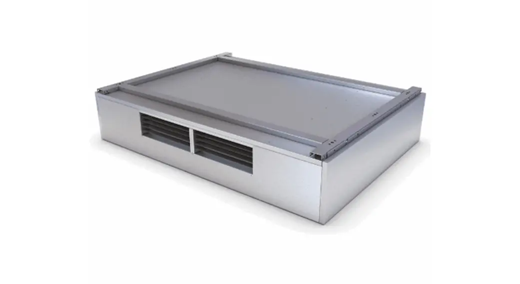
The XB-H range of units shall be manufactured from Aluzinc as a monocoque design lined with Barafoam for high sound absorption characteristics and incorporates a high efficiency, low energy EC blower. The units have the ability to vary the quantity of fresh air supplied between trickle and maximum output, limiting the CO2 gains in the classroom.
Three modes of operation are included; Automatic, Boost and Off, allowing the end user full control over room conditions.
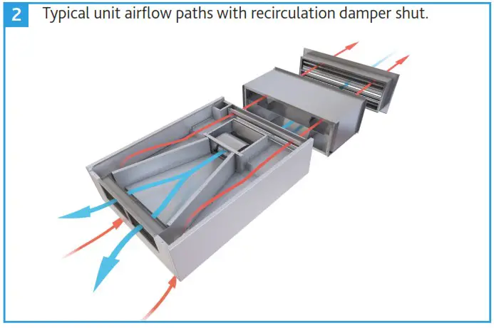
A recirculation path provided within these units ensures adequate temperature delivery in the supply stream for winter conditions, whilst a dedicated discharge path provides an escape route for poor quality air regardless of mode of operation.
Breakout and supply noise levels are maintained under BB93 whilst in normal operation.
These units are available with a standard metallic Aluzinc finish or with painted external panels (RAL9003 Signal White). For further RAL colour options, please contact Nuaire.
Transition pieces, 250mm spiral ducting kits and LPHW modules with ambidextrous coil connections are all available as optional ancillaries which can be retrofitted on site.
General information regarding performance and specifications for the equipment may be obtained from our technical literature, and/or project specific documentation.
Code description: XB-H Hybrid Ventilation Unit
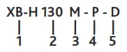
- Range: XB Hybrid
- Size:
130 (2 units required per system)
260 (1 unit required per system) - Control Type:
M = Master
S = Secondary
No Suffix = Not applicable for 260 unit sizes - Finish:
No Suffix = Natural Aluzinc
P = Painted to RAL9003 (Signal White) - Outlet Connection:
No Suffix = Unit for direct room supply.
D = Unit for use with ducting kits.
Code description: XB-H Hybrid Ancillaries
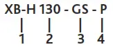
- Range: XB Hybrid
- Size:
130 = Ancillaries to suit XB-H130M or XB-H130S
260 = Ancillaries to suit XB-H260 - Ancillary:
DKIT1 = Ducting Kit
GL = Glazed Louvre
GS = Glazed Sleeve
L = External Weather Louvre
WS = Wall Sleeve
LT = Tempering LPHW, No Valve & Actuator
LP = Primary LPHW, No Valve & Actuator
L2T = Tempering LPHW, 2 Port Valve & Actuator
L2P = Primary LPHW, 2 Port Valve & Actuator
L4T = Tempering LPHW, 4 Port Valve & Actuator
L4P = Primary LPHW, 4 Port Valve & Actuator - Finish:
No Suffix = Natural Aluzinc (Heater Module,
P = Painted to RAL9003 (Signal White) GS & WS Only)
DIMENSIONS (mm) & WEIGHTS (kg)
XB-H Dimensions
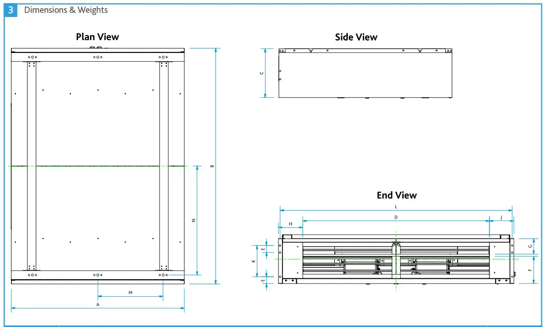
| Unit Code | Unit Dimensions | Unit Weights (Kg) | ||||||||||
| A | B | C | D | E | F | G | H | J | K | L | ||
| XB-H130M | 1250 | 950 | 353.5 | 715 | 50 | 198 | 112 | 63 | 172 | 225 | 926.3 | 135 |
| XB-H130S | 1250 | 950 | 353.5 | 715 | 50 | 198 | 112 | 63 | 172 | 225 | 926.3 | 135 |
| XB-H260 | 1250 | 1700 | 353.5 | 1348 | 50 | 198 | 112 | 176 | 176 | 225 | 1676.3 | 175 |
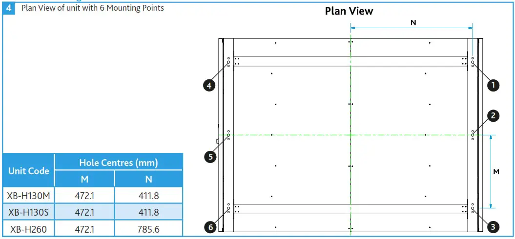
XB-H Mounting Points 4 Plan View of unit with 6 Mounting Points
DELIVERY OF EQUIPMENT
All equipment is inspected prior to despatch and leaves the factory in good condition. Upon receipt of the equipment an inspection should be made and any damage indicated on the delivery note. Particulars of damage and/or incomplete delivery should be endorsed by the driver delivering the goods before offloading by the purchaser.
No responsibility will be accepted for damage sustained during the offloading from the vehicle or on the site thereafter. All claims for damage and/or incomplete delivery must be reported to Nuaire within two days of receipt of the equipment.
Offloading and Handling from the Delivery Vehicle
The weight of the unit and any palletised items is displayed on the unit rating plate or on the packaging. Some units may have an uneven weight distribution, and this will be indicated by labelling where appropriate. Ensure that lifting and handling equipment is adequately rated.
Offloading and positioning of the equipment is the responsibility of the purchaser.
Spreaders should be used when lifting with slings to avoid damage to the casings. Care must be taken to ensure that slings are correctly positioned to avoid crushing and twisting of the unit castings.
XB-H units will be delivered to site in one section. The unit may only be operated in its intended horizontal installation plane.
See Section 3.0 for dimensions and weights.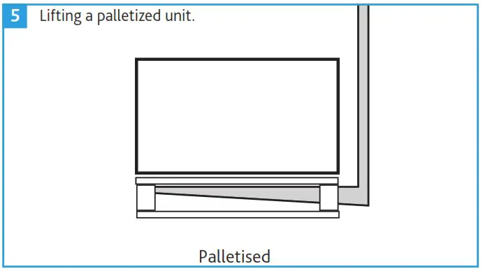 Storage
The equipment must be stored in a dry, internal location. Ductwork connection apertures shall be sealed against the ingress of dust, water and vermin.
If the storage period is to exceed two months, contact Nuaire for guidance on the appropriate “mothballing” procedures. Do not stack units, modules or components.
MECHANICAL INSTALLATION
Installation of the hybrid ventilation units, including all external services and controls should be in accordance with the appropriate authority and MUST conform to all governing regulations e.g. CDM, CIBSE, IEE, and in strict accordance with the applicable Building Regulations.
These units may only be mounted horizontally. The units are heavy, and should be mounted using the fixing brackets supplied or other suitable methods of support. The supporting structure must be assessed for structural suitability.
The final assembled position of the units on the ceiling, must allow for sufficient free space to be available adjacent to the units for future inspection, maintenance, repair and replacement.
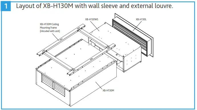
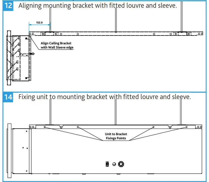
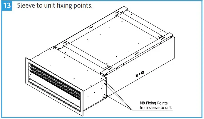
Having decided on the correct installation position for the units, an appropriate external louvre and sleeve for wall or window installation must be installed matching the inlet and exhaust of the unit.
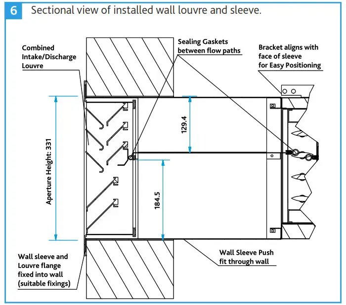
Wall Louvre & Sleeve Installation
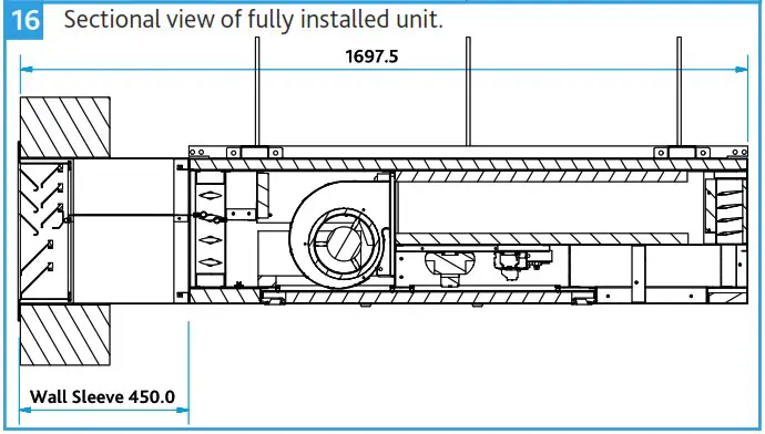
- Prepare a suitable aperture for wall sleeve to the dimensions below.
Unit Aperture Required Height (mm) Width (mm) XB-H130 331 964 XB-H260 331 1714 - Feed the Wall Sleeve from outside to inside. Fit the louvre to the wall sleeve. Ensuring the mid plate seals with the centre divider of the louvre.
- Drill through the louvre to mark suitable hole positions on the wall. Fit the louvre using wall fixings suitable to the wall type.
- When fitting the wall sleeve introduce a slight downward slope to the outside, to encourage any water to drain to outside.
- Make good the inside and outside walls so they are flush with the louvre.
- Proceed to install the main unit (Section 5.3 on page 5).
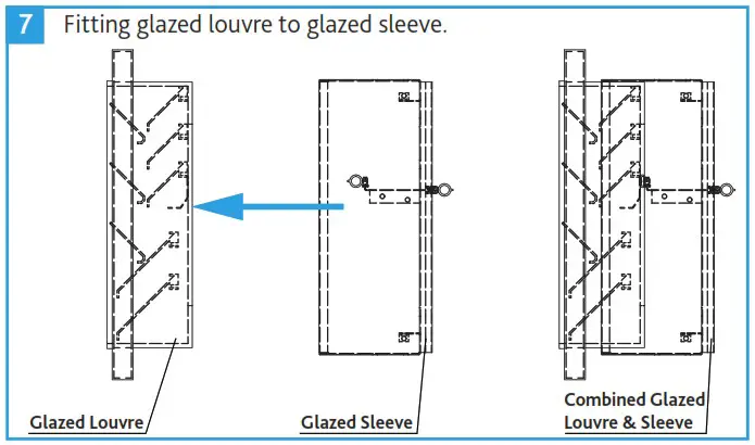
Glazed Louvre & Sleeve Installation
- Fit the glazed louvre as per recommended window installation detail.
- Fit the glazed sleeve over the top of the back of the louvre, ensuring the mid plate seals with the centre divider of the louvre.
- Proceed to install the main unit (Section 5.3 on page 5).
Unit Code Window Frame Dimensions (mm) Height Width Depth XB-H130-GL 386 956 25 XB-H260-GL 386 1706 25 
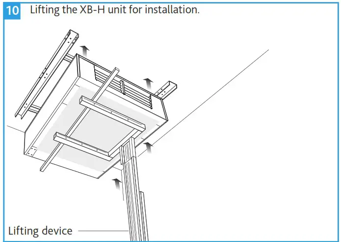
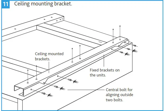
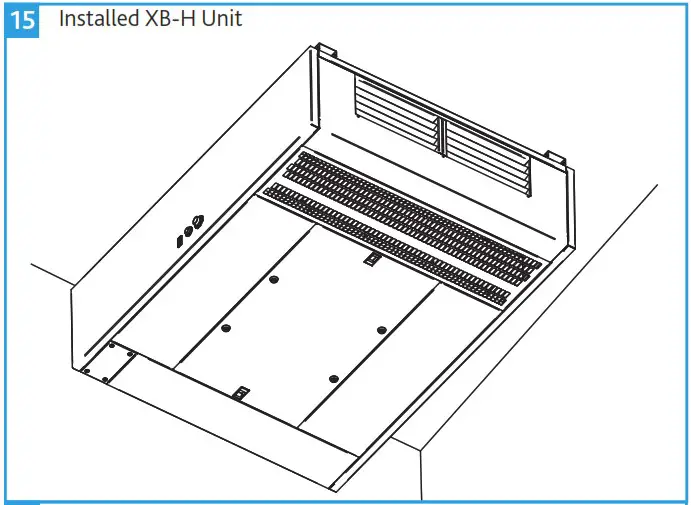
XB-H Unit Installation
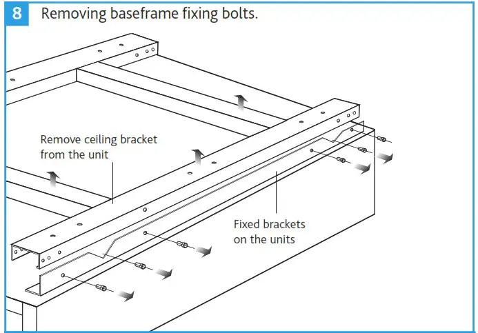
- Remove the fixing bolts and ceiling mounting bracket from the unit (Figure 8).
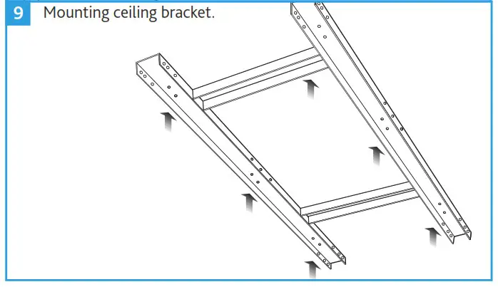
- Mark positions for mounting the ceiling bracket (Figure 9). The external louvre / wall sleeve must be installed first.
- Ensure that the fixing of the ceiling bracket to the ceiling allows for the weight of the XB-H unit and all ancillaries to be suspended from it.
- The unit may be lifted up to be aligned and installed using the fixing bolts. Position the fixing bolts through unit bracket and mounting bracket using the central one of the three bolt holes in the “V” shape to align the outside two bolt holes.
- It is important that the unit and any ancillaries are aligned and fit tightly together so that maximum performance is achieved.


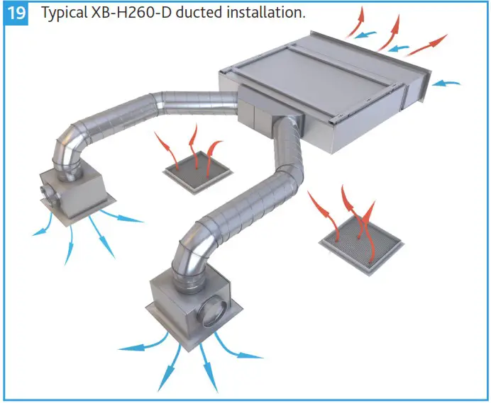
Ducting Kit
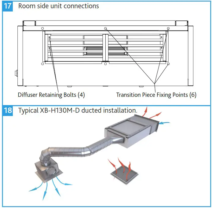
- If the ducting kit is to be retrofitted, otherwise skip this step: Using an 8mm nut driver, loosen the blade diffuser by removing the four nut head screws that are accessible through the diffuser blades. Remove the blade diffuser from the unit.
- Xix the ducting transition piece to the front of the unit using the six M8 fixings provided. Seal between the transition and unit to ensure no air leakage.
- Remaining pieces of ducting can now be fitted to the transition piece, ensure all connections are adequately sealed.
LPHW Module
This range of units is available with an optional LPHW module whose coil connection side can be flipped to avoid handing issues (right handed as default).
Changing the LPHW Pipe Connection Side
- Remove access cover from LPHW module, gently remove the temperature sensor from the supply side grommet and replace in the opposite grommet. Replace LPHW access.
- Unscrew the 3 – axis aligning clamps and remove from the half on the module, re-screwing on the opposite side of the module.
- Drop the module from the bracket, and remove the blade diffuser from the front, turn the module around and re-fit the diffuser in the new front of the module.
- Lift the module back into place fixing on the bracket support, once fixed re-fix the 3-axis aligning clamps and tighten to affect an air seal between the unit and module.
Fitting the LPHW Module
All necessary fixings and seals are provided and can be located inside a clear, sealed, polythene bag attached to the LPHW module.
- Unscrew the blade diffuser from the main unit, using a 8mm nut driver on the four bolts located on the inside of the blade diffuser on the sides and remove.
- Fit side seals from LPHW module onto main unit face and fit the blade diffuser into LPHW module on the supply side.
- Lift Module into place and fix through the ceiling bracket support using m8 hex head bolts provided.
- Remove the central nut and bolt of the two 3-axis clamps releasing half of the clamps. Attach the unattached clamp half to the main unit via the factory fitted screw inserts and M6 cap head bolts provided. Refit the central nut and bolt through both half’s of the alignments clamps and tighten.
XB-HCO2 (Default CO2 Sensor Ancillary)
Mounting Location
The device is suitable for wall mounting.
- Recommended height: 1.50 m above floor.
- Do not mount the devices in recesses, shelves, behind curtains or doors, or above or near heat sources.
- Avoid direct solar radiation and drafts.
- Seal the conduit box or the installation tube, as air currents can affect sensor readings.
- Adhere to allowed ambient conditions.
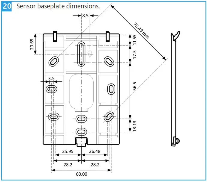
Wall Mounting
The device is designed for wall-mounting. Remove the breakout on the housing before putting the cable into the gaining channel. A 30m cable is supplied as standard. Cabling can be pushed into channels on the rear. A plug is enclosed with the device. The sensor wiring diagram is included in the main unit wiring diagrams.
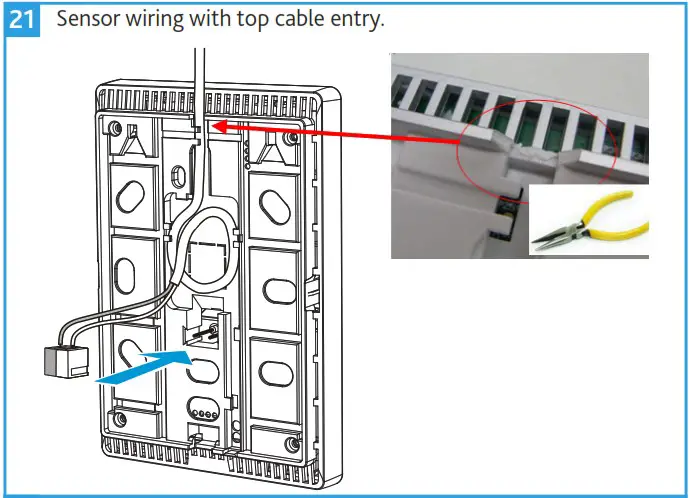
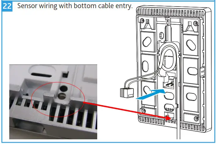
Cable Conduits on the Wall
Keep a distance of 30 mm (from above) / 20 mm (from below) to the base plate (A), so that the device (B) can be snapped onto the base plate.
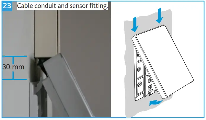
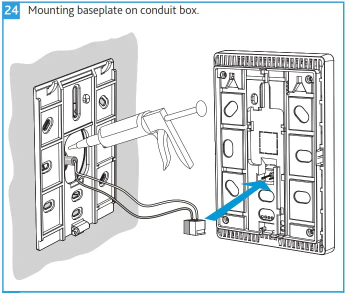
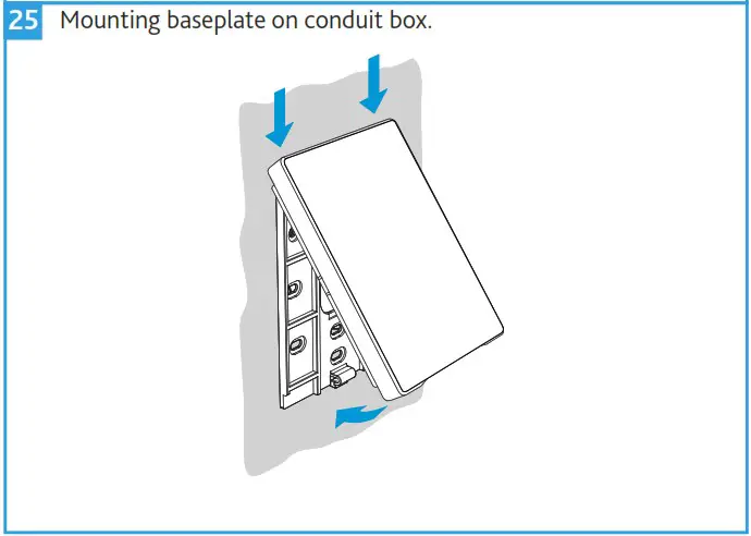
Mounting Over a Conduit Box
The base plate (A) has screw holes for all common flush-mount boxes.The screw head height must not exceed 3 mm. The installing tube must be sealed or cold or warm air may enter the device and cause faulty temperature readings by the internal sensor.
Dismounting
Using a flat head screwdriver, release the latching clip at the bottom of the sensor.
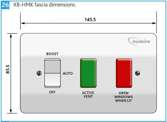
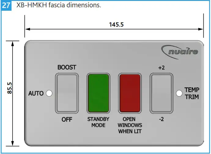
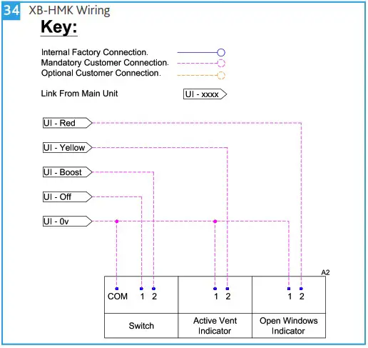
XB-HMK / XB-HMKH User Controls (Default Ancillary)
This user control is suitable for indoor use only. Mount with the single gang electrical box (not provided) on a vibration free vertical surface away from any direct source of heat and areas where it would be subjected to water spray. Ensure mounting box is securely fixed to the wall.
Connect a sheathed earth cable to the earth terminal in the box. Also, connect a sheathed earth lead between the same box earth terminal and the earth terminal on the grid frame.
Ease the other conductors through the aperture in the front of the Grid frame and screw the frame to the box. Connect the supply cables to the Grid module (Figure 2). Always remember to tighten terminal screws securely. Once the module has been wired, carefully push it back through the grid frame until the clip on the top of the module has clicked into place (Figure 1), ensuring no wires are pinched or trapped.
If necessary the modules can be removed by placing the blade of a screwdriver just above the top clip and carefully levering it out (Figure 2).
Ensure everything in the assembly is secure and is wired correctly, then locate the front plate over the assembly and secure using the screws provided. Do not over tighten the screws; to do so may damage the front plate, fixing screws, or Grid frame.
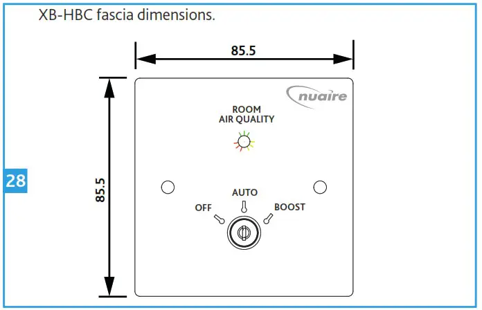
XB-HBC User Control (Optional Ancillary)
This user control is suitable for indoor use only. Mount with the single gang electrical box (not provided) on a vibration free vertical surface away from any direct source of heat and areas where it would be subjected to water spray. Ensure mounting box is securely fixed to the wall.
Wire the user control as per the XB-HBC wiring diagram, ensuring wires are fully inserted into the relevant terminals and that no bare copper wire is visible. Tighten the screws securely onto the copper wire, not the outer sheathing.
Gently press the socket back into place over the mounting box. Take care not to trap any wires between the wall and the socket. Insert and tighten the retaining screws provided.
ELECTRICAL CONNECTIONS
Before connecting the product to the power supply or the power outlet, ensure that:
- The fan data plate/label (voltage and frequency) correspond to those of the electrical mains.
- The electrical power supply/socket is adequate for maximum unit power. If not, contact a qualified technician.
The electrical system to which the unit is connected must comply with regulations. Further unit details including fan speed etc. can be found on the unit label.
| Unit | Electrical Details | ||
| Full Load Current | Voltage | Frequency | |
| XB-H130M | 0.7 A | 230 V | 50 Hz |
| XB-H130S | 0.7 A | 230 V | 50 Hz |
| XB-H260 | 1.4 A | 230 V | 50 Hz |
Mains Connection
Mains cables should be suitably sized and terminated at the terminals shown on the appropriate diagram.
Wiring
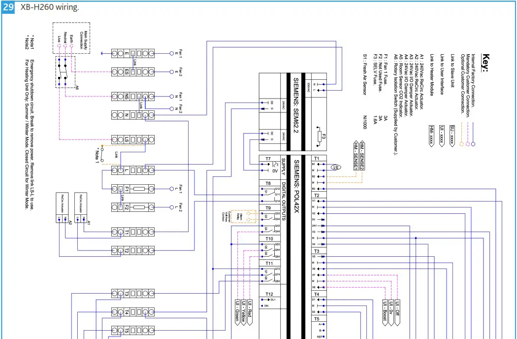
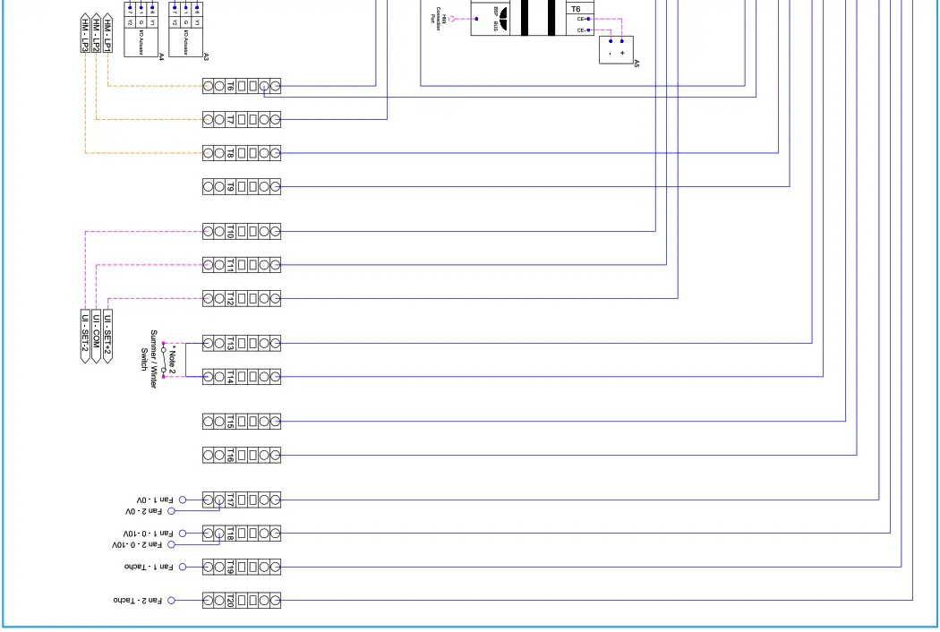
XB-H260 Unit Wiring Diagram
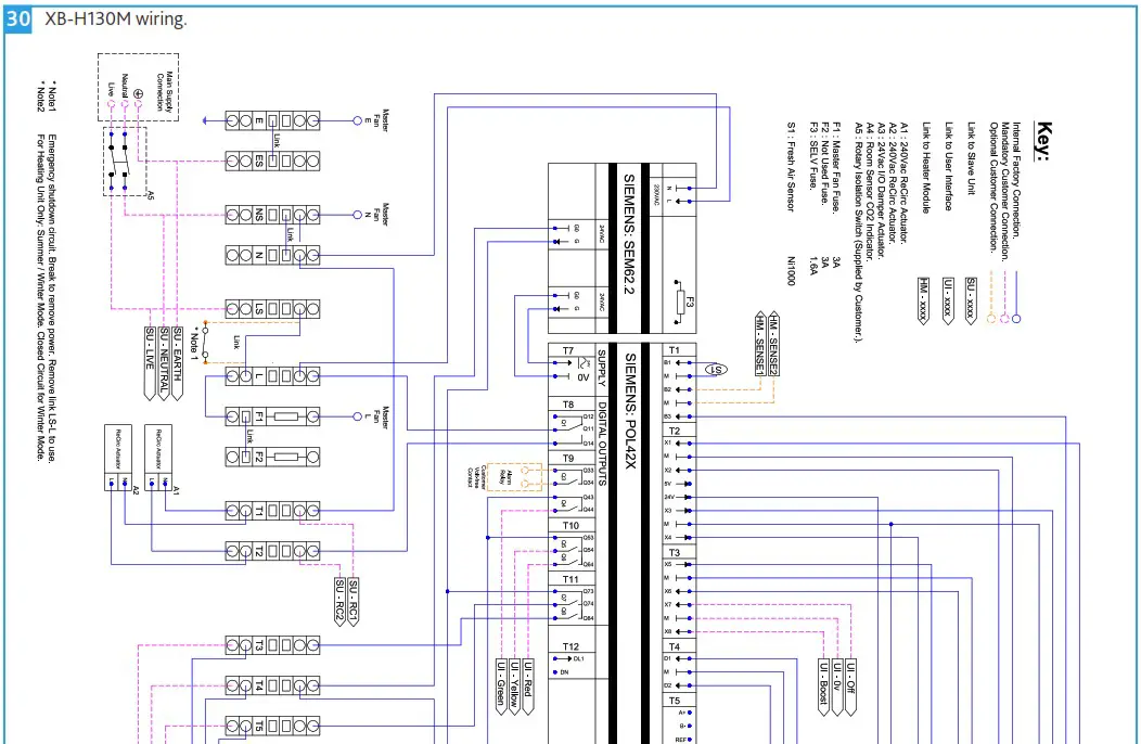
XB-H130M Unit Wiring Diagram
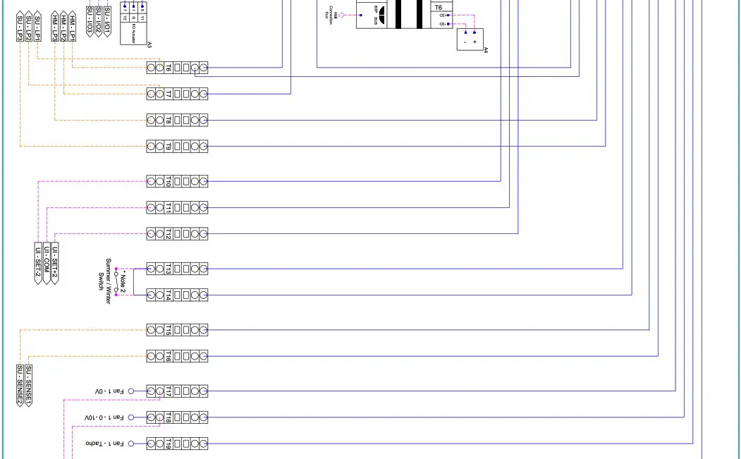

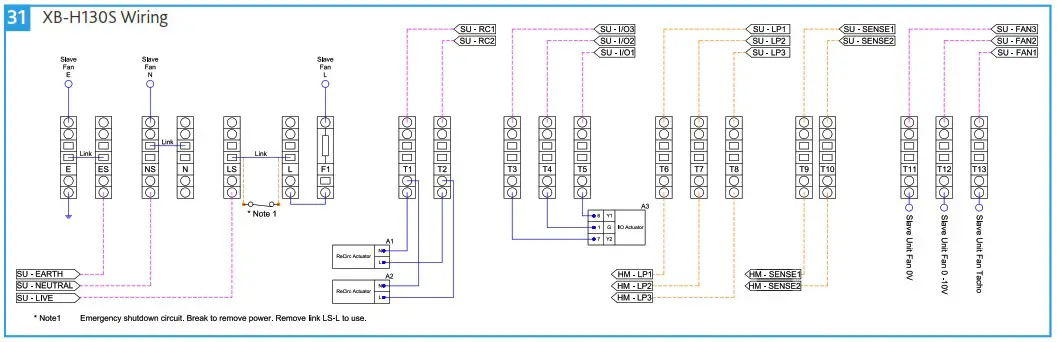
XB-H130S Unit Wiring Diagram
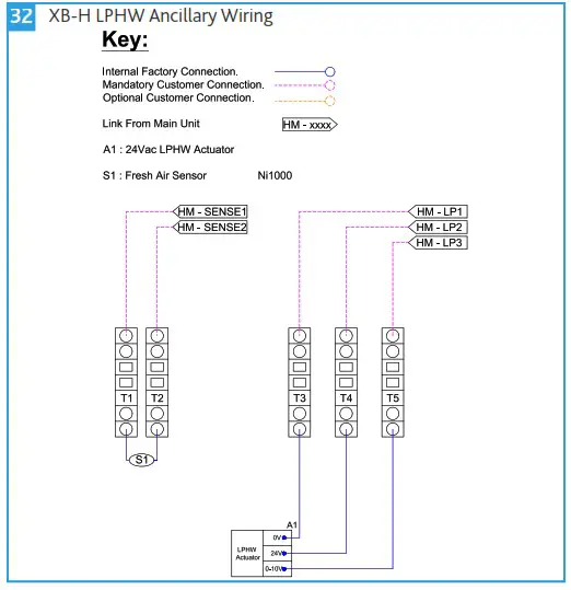
| XB-H LPHW Ancillary Wiring Diagram
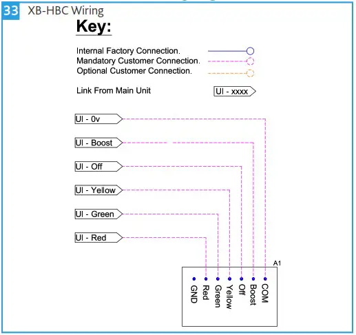
| XB-HBC User Control Wiring Diagram
|
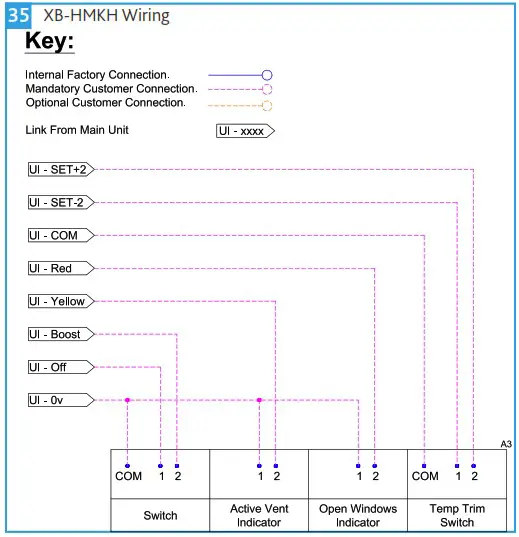
| XB-HMK User Control Wiring Diagram
| XB-HMKH User Control Wiring Diagram
|
OPERATION
The unit operates through Scheduling, either through local scheduling which can be customised during commissioning standard is Monday to Friday 7:30 to 16:30 or through BACnet start / stop. When the unit is in the occupied time then it will react based on in-room CO2 and temperature which is read through the XB-HCO2. The unit goes through three stages of operation based on conditions, when the “occupied” setpoints are breached then the fresh air damper opens to allow fresh air into the unit, if this fresh air is above the min setpoint set at 12 then the re-circulation damper will open allowing a low-resistance natural air path into the room. If natural airflow is not sufficient and the in-room conditions exceed the “warning” setpoints then the unit will close the damper to a min setpoint of 30% and start the fan on min 2.5V. This will then proportional rise with the increase of the In-room CO2 or Temp until the “Max” Setpoints are breached at this point the unit will be operating at its maximum to increase fresh air to the space. In Winter when the fresh air is below 12 the re-circulation damper will not open which stops the natural air path to avoid the dumping of cold air, also when the “warning” setpoints are breached and the fan begins then the re-circulation damper will open to allow inroom air to be mixed into the fresh air stream and temper the supply.
During occupied times the user in the room can have local control over the unit by using the XB-HMK, this will allow the user to take the unit into either Boost, or temporary off. The boost will run for 60 minutes by default after pressing the button and returning it back to auto, but will automatically cancel out if the in-room CO2 and Temperature drop below the occupied setpoints. The off will turn the fans and dampers off while the button is in the off position. If the unit comes with LPHW then the user control will have temperature trim rocker switch, this will allow the user to shift the setpoints up or down by 2 degrees which in turn changes when the heating and cooling activates. This lasts for a default time of 60 minutes, however the command can be cancelled with a long press of 5 seconds.
COMMISSIONING
This section describes the commissioning of the main control unit (XB-H130M or XB-H260), CO2 sensor (XB-HCO2) and heating if present in the unit in question.
Due to the nature of the Master/Secondary control used, commissioning of the XB-H130S is not required.
Master/Secondary control is a model of control where one unit (XB-H130M) has unidirectional control over another unit (XB-H130S).
Before commissioning, ensure the wiring of the unit(s) and all ancillaries has been correctly completed.

Commissioning Device (XB-HCD)
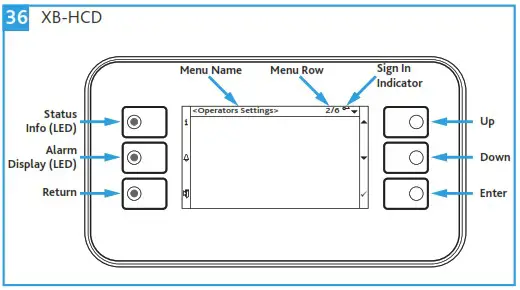
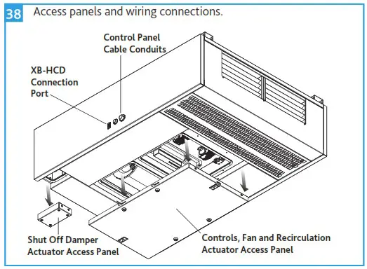
A Hybrid Commissioning Device (XB-HCD) is required to commission the units, can be plugged into the HMI commissioning port located on the side of the unit (Figure 38) and is available from Nuaire.
Quick Commissioning
Password Sign-In
Using `Up’ & `Down’ buttons (Figure 36) scroll to `Password Sign-in’ located at the bottom of the list and press the `Enter’ button. Input the password (default password: 5 6 7 8) to sign-in, taking you to the `Operator Menu’.
Time and Date
Whilst signed in, press `Return’ to take you back to the `Main page’. Scroll to the time and date entry located at the top of the list and press the `Enter’ button. Set the time and date using the `Up’ and `Down’ keys, pressing `Enter’ to confirm.
Unit & Heating Selection
As default, all XB-H controls leave Nuaire’s factory pre-configured to run an XB-H130M and XB-H130S pairing with heating. In the event of an alternative configuration of units and ancillaries being used, follow the below process applicable to the site configuration in question.
Whilst signed in, select `Operators Menu’ (13/15) and press `Enter’ to access this menu. Scroll to `QMX3 + Heating Setup’ (7/7) and press `Enter’ to access the setup menu.
If the site configuration is a single XB-H130M: Select `2/Select Part No. =’ (2/7) and press `Enter’ to access this sub menu. Scroll to `QMX-P70′ and press `Enter’ to confirm.
If the site configuration is a single XB-H260: Select `2/Select Part No. =’ (2/7) and press `Enter’ to access this sub menu. Scroll to `2Fn-H260′ and press `Enter’ to confirm.
If heating is not present: Select `1/Heating Valve’ (1/7) press `Enter’, select `Not_Used’ and press `Enter’ to confirm.
XB-HCO2
Once the unit and heating selection setup has been performed as described in Section 8.2.3 the CO2 sensor can be commissioned.
Whilst signed in, select `Operators Menu’ and press `Enter’ to access this menu. Scroll to `QMX3 + Heating Setup’ and press `Enter’ to access the setup menu.
Manual input will be required at the following menu rows:
3/14 – Restart the commissioning device – Press `Enter’ on restart step scroll to `Execute’ and press `Enter’ to restart.
6/14 – Set to `Auto’ and press `Enter’.
9/14 – Set to `AddrSnr’ and press `Enter’.
11/14 – Set to `Config’ and press `Enter’.
14/14 – Restart the commissioning device – Press `Enter’ on restart step scroll to `Execute’ and press `Enter’ to restart.
Time Schedule or BMS Operation
The unit will be available in two main modes, Time Schedule or BMS operation through the RS-485 for BACnet MS/TP (wired to T5 on unit control panel).
Whilst signed in, select `Operators Menu’ and press `Enter’, press `Enter’ again to access `Operators Settings’ menu. Select `Off/24HrRun/TimeSch’ and press `Enter’. Select the appropriate mode of operation as given in the table below and press `Enter’ to activate.
| Operation | Description |
| 24HrRun | Unit controlled via BMS. |
| TimeSch | Unit controlled via built-in scheduling. |
| Stop | Unit fans do not operate. |
If operating the units via the `TimeSch’ option then press `Return’ from the `Operators Settings’ menu to go back to `Operators Menu’.
Scroll to `Daily Time Schedule’ and then set:
- The time periods the unit is required to start, using the `Occupied’ setting and stop using the `UnOccupied’ setting.
- The days the unit is required to operate, as default the unit operates Monday-Friday 7:30-18:30.
XB-HMK User Control Minimum Off Time
If you intend to use the XB-HMK User control. Then the unit controls will need the `Minimum Off Time’ to be set.
Whilst signed in, select `Operators Settings’ and press `Enter’ to access this menu. Scroll to `Minimum Off time’ and press `Enter’ to access the off time menu.
Here you can select the length of time the unit will remain off, when the reactive “Off” switch is pressed. Default period of time is 0 minutes.
Optional Commissioning
Night Purge
This setting is optional, determines whether the unit provides Night Free Cooling or not and is for use with Time Schedule operation only.
Whilst signed in, select `Operators Menu’ and press `Enter’ to access this menu. Scroll to `Night Free Clg Menu’ and press `Enter’ to access the night cooling menu.
Select `Program Enable?’ and press `Enter’ to access the NFC program sub menu. Scroll to `NPurge Time Schedule’ and press `Enter’ to access the NFC Time Schedule menu.
The Start and Stop times for Night Free Cooling can be accessed and changed here. If this setting has been activated the unit will operate between 3-5am Mon-Fri when the NFC control logic conditions have been met.
Variable or Constant Fan Speed
This setting determines whether the unit operates at variable speeds as dictated by the room air quality or at a fixed speed.
Whilst signed in, select `Fan = Variable’ and press `Enter’ to access this menu. Select the appropriate mode of operation as given in the table below and press `Enter’ to activate.
| Setting | Description |
| Variable | Fan speed varies according to air quality |
| Constant | Fan speed is constant |
If the ‘Constant’ setting is activated whilst signed in, the controller will automatically progress to the next field ‘Set-Speed=’, the default constant speed value is 50%, but this can be altered to any integer between 0-100%.
Modifying Set-points
Whilst signed in, select `Operators Menu’ and press `Enter’ to access this menu. Scroll to `Operators Settings’ and press `Enter’ to access the settings menu. To modify these settings, scroll to the appropriate option and press `Enter’. Modify the set-points between the range of values as required.
| Set-point Name | Set-Point Range (Default Value) |
| Occupied Temp Sp | 18-23 (21)°C |
| Warning/FanRun Temp SP | 22-25 (23)°C |
| Max Room Temp SP | 24-26 (25)°C |
| Occupied CO2 SP | 750-950 ppm |
| Warning/ FanRun CO2 SP | 850-1150 ppm |
| Max Room CO2 SP | 1000-1500 ppm |
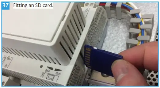
SD Card
An SD card (included with XB-HCD) can be used to download, transfer and store custom setpoints between control units or for later use. Use a blank 4Gb or lower SD Card.
Saving Custom Setpoints
Isolate the unit from the power supply. Access the control panel section and use a small flat bladed screwdriver to release the WAGO end stop catch. Remove the end stop, insert an SD Card into the slot on the end of the controller (Figure 37). Restore power to the unit.
Whilst signed in, select `System Overview’ and press `Enter’. Scroll to `SD Card’ press `Enter’. Scroll to `Settings Save to SD’ press `Enter’. Scroll to `Execute’ press `Enter’.
Isolate the unit from the power supply, access the control panel section, remove the SD Card and replace the end stop. Restore power to the unit.
Loading Custom Setpoints
Isolate the unit from the power supply. Access the control panel section remove the WAGO end stop and insert the SD Card. Restore power to the unit.
Whilst signed in, select `System Overview’ and press `Enter’. Scroll to `SD Card’ press `Enter’. Scroll to `Settings Load from SD’ press `Enter’. Scroll to `Execute’ press `Enter’.
Isolate the unit, access the control panel, remove the SD Card and replace the WAGO end stop. Restore power to the unit.
 POINTS LIST
 POINTS LIST
| BACnet Name | Description | BACnet Point | Default Value | Units [Range] | Point Type |
| St24hrsch | Unit Enable on Remote or Local Schedule | 1000 | [2] 24HrRun. | [1] Stop, [2] 24HrRun, [3] TimeSch | MV |
| FreshAirT | Fresh Air Temperature | 1001 | Value | °C | AI |
| MainSuAir | Main Supply Air Temperature | 1002 | Value | °C | AI |
| 2ndSuAir | Secondary Supply Air Temperature | 1003 | Value | °C | AI |
| P70RmTm | Room Temperature | 1006 | Value | °C | AI |
| P70RmCO | Room CO2 | 1007 | Value | PPM | AI |
| EmmSTOP | Emergency Stop | 1010 | [0] Auto | [0] Auto, [1] Stop | BI |
| AUTOSwt | User Auto Mode Switch | 1011 | [1] Auto | [0] —, [1] Auto | BI |
| OFFSwt | User Off Mode Switch | 1012 | [0] — | [0] —, [1] Off | BI |
| BOOSTSwt | User Boost Mode Switch | 1013 | [0] — | [0] —, [1] Boost | BI |
| FnATacho | Fan A Tacho Status | 1014 | [0] Stopped | [0] Stopped, [1] Running | BI |
| FnBTacho | Fan B Tacho Status | 1015 | [0] Stopped | [0] Stopped, [1] Running | BI |
| SumWinSwt | Summer / Winter Switch | 1016 | [0] Summer | [0] Summer, [1] Winter | BI |
| TTrmInDI | Temperature Trim Increase Digital Input | 1017 | [0] Off | [0] Off, [1] On | BI |
| TTrmInc | Temperature Trim Increase Status | 1018 | [0] Auto | [0] Auto, [1] Increased | BI |
| TTrmDeDI | Temperature Trim Decrease Digital Input | 1019 | [0] Off | [0] Off, [1] On | BI |
| TTrmDec | Temperature Trim Decrease Status | 1020 | [0] Auto | [0] Auto, [1] Decreased | BI |
| HtgTmpSP | Heating Temperature Setpoint | 1025 | 19 | °C [-64-64] | AI |
| OccTmpSP | Occupied Temperature Setpoint | 1026 | 21 | °C [-64-64] | AI |
| WrnTmpSP | Warning Temperature Setpoint | 1027 | 23 | °C [-64-64] | AI |
| MaxTmpSP | Maximum Temperature Setpoint | 1028 | 25 | °C [-64-64] | AI |
| OccCO2SP | Occupied CO2 Setpoint | 1029 | 800 | PPM [500-2000] | AI |
| WrnCO2SP | Warning CO2 Setpoint | 1030 | 1000 | PPM [600-2500] | AI |
| MaxCO2SP | Maximum CO2 Setpoint | 1031 | 1500 | PPM [800-4000] | AI |
| FAChgOvSP | Fresh Air Changeover Setpoint | 1032 | 8 | °C [5-15] | AI |
| FrzTempSP | Frost Protection Setpoint | 1033 | 4 | °C [2-10] | AI |
| SuMinT_SP | Supply Temperature Minimum Setpoint | 1034 | 14 | °C [12-20] | AI |
| SuMaxT_SP | Supply Temperature Maximum Setpoint | 1035 | 35 | °C [16-60] | AI |
| BoostTime | Boost Run Timer | 1040 | 60 | Minutes [1-90] | AI |
| OFF_Time | Minimum Off Timer | 1041 | 0 | Minutes [0-180] | AI |
| TTrimTime | Temperature Trim Timer | 1042 | 60 | Minutes [1-90] | AI |
| FloFailTime | Airflow Fail Alarm Delay | 1043 | 20 | Seconds [0-60] | AI |
| FanMinSpd | Minimum/Trickle Fan Speed | 1045 | 3 | V [1-9] | AI |
| FanMaxSpd | Maximum/Design Fan Speed | 1046 | 8 | V [2-10] | AI |
| FanBoostSpd | Boost Fan Speed | 1047 | 8 | V [6-9] | AI |
| FanCnstSpd | Constant Fan Speed | 1048 | 50 | % [0-100] | AI |
| HtgSPTrim | Heating Temperature Setpoint Trim | 1050 | 19 | °C [0-50] | AI |
| OccSPTrim | Occupied Temperature Setpoint Trim | 1051 | 21 | °C [0-50] | AI |
| WrnSPTrim | Warning Temperature Setpoint Trim | 1052 | 23 | °C [0-50] | AI |
| MaxSPTrim | Maximum Temperature Setpoint Trim | 1053 | 25 | °C [0-50] | AI |
| FAirDmp | Fresh Air Damper Status | 1055 | Value | % [0-100] | AO |
| FnSigAO | Fan Speed Status | 1056 | Value | V [0-10] | AO |
| MainHtgAO | Master Heating Status | 1057 | Value | % [0-100] | AO |
| 2ndHtgAO | Secondary Heating Status | 1058 | Value | % [0-100] | AO |
| RecDamper | Recirculation Damper Status | 1060 | Value | [0] Close, [1] Open | BO |
| UnitSta | Unit Status | 1061 | Value | [1] Off, [2] EmergSTOP, [3] TestMode, [4] BoostMode, [5] RunMode, [6] NightClg, [7] UnitFault, [8] Hiberate | MV |
| HealthyDO | Healthy Status | 1062 | Value | [0] Off, [1] Ok | BO |
| CommAlmDO | Common Alarm Status | 1063 | Value | [0] OK, [1] Alm | BO |
| SenFlt | Sensor Fault Output | 1064 | Value | [0] OK, [1] Alm | BO |
| P70SenFlt | Sensor Status | 1065 | Value | [0] OK, [1] Alarm | BO |
| FnASta | Condition of Fan A | 1066 | Value | [0] OK, [1] Alarm | BI |
| FnBSta | Condition of Fan B | 1067 | Value | [0] OK, [1] Alarm | BI |
| GrnLED_DO | Green LED Digital Output | 1068 | Value | [0] Off, [1] On | BO |
| YelLED_DO | Yellow LED Digital Output | 1069 | Value | [0] Off, [1] On | BO |
| RedLED_DO | Red LED Digital Output | 1070 | Value | [0] Off, [1] On | BO |
| PreHeatTm | Preheat Time | 1076 | 60 | Minutes [1-240] | MV |
| PreHeatSP | Preheat Setpoint | 1077 | 15 | °C [12-20] | MV |
| PreHeatSta | Preheat Enable State | 1079 | [0] Off | [0] Off, [1] On | BV |
| OccStrHr | Occupied Time (Hours) | 1080 | 7 | Hours [1-23] | MV |
| OccStrMin | Occupied Time (Minutes) | 1081 | 30 | Minutes [1-59] | MV |
| UnOccHr | Unoccupied Time (Hours) | 1083 | 18 | Hours [1-23] | MV |
| UnOccMin | Unoccupied Time (Minutes) | 1084 | 30 | Minutes [1-59] | MV |
| Monday | Monday Enable | 1085 | [2] Yes | [1] No, [2] Yes | MV |
| Tuesday | Tuesday Enable | 1086 | [2] Yes | [1] No, [2] Yes | MV |
| Wednesday | Wednesday Enable | 1087 | [2] Yes | [1] No, [2] Yes | MV |
| Thursday | Thursday Enable | 1088 | [2] Yes | [1] No, [2] Yes | MV |
| Friday | Friday Enable | 1089 | [2] Yes | [1] No, [2] Yes | MV |
| Saturday | Saturday Enable | 1090 | [1] No | [1] No, [2] Yes | MV |
| Sunday | Sunday Enable | 1091 | [1] No | [1] No, [2] Yes | MV |
| TmSchSta | Time Schedule State | 1092 | [0] Off | [0], Off, [1] On | MV |
| NP_Ena | Night Purge Enable | 1095 | [1] Disable | [1] Disable, [2] BMS_On, [3] Local_Sch | MV |
| NP_MinFA | Night Purge Minimum Fresh Air | 1096 | 10 | °C [5-14] | AV |
| NP_AveTmp | Average Day Temperature | 1097 | Value | °C | AI |
| NP_Mode | Night Purge Enable Status | 1098 | [0] Winter | [0] Winter, [1] Summer | BO |
| FATmpLo | Under Temperature Alarm | 1099 | [0] No | [0] No, [1] Yes | AI |
| FATmpHi | Over Temperature Alarm | 1100 | [0] No | [0] No, [1] Yes | AI |
| NP_StrHr | Night Purge Start Time (Hour) | 1105 | 3 | Hours [1-6] | MV |
| NP_StrMin | Night Purge Start Time (Minutes) | 1106 | 0 | Minutes [1-59] | MV |
| NP_StpHr | Night Purge Stop Time (Hour) | 1107 | 5 | Hours [1-6] | MV |
| NP_StpMin | Night Purge Stop Time (Minutes) | 1108 | 0 | Minutes [1-59] | MV |
| NP_MonEn | Night Purge – Monday | 1109 | [2] Enable | [1] Disable, [2] Enable | MV |
| NP_TueEn | Night Purge – Tuesday | 1110 | [2] Enable | [1] Disable, [2] Enable | MV |
| NP_WedEn | Night Purge – Wednesday | 1111 | [2] Enable | [1] Disable, [2] Enable | MV |
| NP_ThuEn | Night Purge – Thursday | 1112 | [2] Enable | [1] Disable, [2] Enable | MV |
| NP_FriEn | Night Purge – Friday | 1113 | [2] Enable | [1] Disable, [2] Enable | MV |
| NP_SatEn | Ngith Purge – Saturday | 1114 | [1] Disable | [1] Disable, [2] Enable | MV |
| NP_SunEn | Night Purge – Sunday | 1115 | [1] Disable | [1] Disable, [2] Enable | MV |
| NP_Runs | Night Purge Running | 1116 | [0] No | [0] No, [1] Yes | BV |
| NP_Achie | Night Purge Temperature Achieved | 1117 | [0] No | [0] No, [1] Yes | BV |
| AppNo | Software Version | 1125 | AI | ||
| SW_Date | Software Date | 1126 | AI | ||
XB-H ACCESS
The unit configuration is such that the intake and exhaust connections are positioned on the atmosphere side of the unit on its centre line. The corresponding supply and extract grilles are positioned on the room side of the unit, and do not require connections.
The standard XB-H unit configuration is shown in (Figure 4). Unit handing information will not be requested for this range, and units will be supplied in this format as standard.
These units are provided with bottom access and must be installed with 350mm minimum clearance below the units. With this clearance, fans, actuators and the controls can be accessed, and changed if necessary.
The controls access panel can be unlocked by inserting a flat head screwdriver into the each of the locking latch grooves and turning anticlockwise (1/4 turn), keys are neither required nor provided by Nuaire. After the controls panel is unlocked the sliding latches can be used to release the control panel from the unit.
The actuator access is secured with pozi head screws.
When refitting an access panel it is important to ensure that any and all fixings, latches or locks are in place and secure.
IMPORTANT
Access panel keys are neither required nor provided by Nuaire.
IMPORTANT
Safety first! Before commencing any work ensure:
- That all appropriate risk assessments have been carried out and the required safety measures have been taken.
- That you understand the work required.
- That you are trained and competent to carry it out.
IMPORTANT
Isolation – Before commencing work make sure that the unit and Nuaire control are electrically isolated from the mains supply.
MAINTENANCE
It is important that maintenance checks are recorded and that the schedule is always adhered to, in all cases, the previous report should be referred to.
Maintenance Schedule
Routine Maintenance
- Clean all areas of unit and treat any areas of corrosion.
- Check all access doors for leakage and if necessary locks should be adjusted and any replacement gasket materials should be replaced as required.
Every 6 Months
- Check fin coil banks and heat exchangers. If necessary clean with a soft brush or vacuum. Check for signs of contamination.
- Check fan operation and soiling. If necessary clean with a soft brush or vacuum.
Annually
- Thoroughly inspect the unit and its components for corrosion, acting immediately to treat/restore any damaged areas.
- All electrical terminals within the unit should be tightened.
- Check all earth connections.
- Check control dampers blades.
- Check operation of damper actuators and linkages and adjust as necessary.
- Coil faces should be inspected and any dust removed.
Fan Replacement
Remove the main access panel to reveal the fan section. Disconnect the wiring loom(s) at the plugs provided. Unscrew the M5 hex head bolts at the fan plate.
For XB-H130 units lift the fan and fan plate up, levering the bottom of the fan plate away from its mounting latch. The fan should now be released for withdrawal. Reverse the procedure when installing the new fan.
For XB-H260 units slide the fan to be replaced to the centre of the unit. A small section of the fan slide rail has been removed and will allow the fan to be removed from the unit. Reverse the procedure when installing the new fan.
Actuator Replacement
Recirculation Damper Actuators
Remove the main access panel to reveal the control section. The two recirculation damper actuators are located in this section and can be replaced if necessary.
Shut Off Damper Actuators
Remove the shut off damper rear actuator access panel. Use a size 4 Allen key to loosen the grub screw securing the actuator to the spindle. Unscrew the two M4 x 16 pozi head screws and slide the actuator away from the spindle before removing it from the unit. Replace as necessary ensuring the bronze adaptor is fitted to the actuator.
WARRANTY
XB-H units have a 2 year warranty for peace of mind. The warranty starts from the day of delivery and includes parts and labour for the first year. The remaining period covers replacement parts only.
This warranty is void if the equipment is modified without authorisation, is incorrectly applied, misused, disassembled, or not installed, commissioned and maintained in accordance with the details contained in this manual and general good practice.
The product warranty applies to the UK mainland and in accordance with Clause 14 of our Conditions of Sale. Customers purchasing from outside of the UK should contact Nuaire International Sales office for further details.
Failure to maintain the unit as recommended will invalidate the warranty.
END-OF-LIFE AND RECYCLING
Where possible Nuaire use components which can be largely recycled when the product reaches its end-of-life:
- Fans, motors, controls, actuators, cabling and other electrical components can be segregated into WEEE recycling streams.
- Sheet metal parts, aluminium extrusion, heating/cooling coils and other metallic items can be segregated and fully recycled.
- EPP, plastic ducting, nylon corner pieces, plastic heat exchangers, packaging material and other plastic components can be segregated into mixed plastic and widely recycled.
- Cardboard packaging, wood, used filters and other paper components can be largely recycled or fully processed in energy from waste centres.
- Remaining items can be further segregated for energy from waste centres or, as a last resort, sent to landfill. Please call After Sales Support for further information on items not listed above.
IMPORTANT
Ensure that Nuaire product is made safe from any electrical / water / refrigerant supplies before dismantling commences. This work should only be undertaken by a qualified person in accordance with local authority regulations and guidelines,
taking into account all site based risks.
AFTER SALES AND REPLACEMENT PARTS
For technical assistance or further product information, including spare parts and replacement components, please contact the After Sales Department.
If ordering spares please quote the serial number of the unit together with the part number, if the part number is not known please give a full description of the part required. The serial number will be found on the identification plate attached to the unit casing.
Telephone 02920 858 400 [email protected]
NOTES
___________________________________________
Nuaire | Western Industrial Estate | Caerphilly | CF83 1NA | nuaire.co.uk
18 17. 03. 21. Document Number 671902


