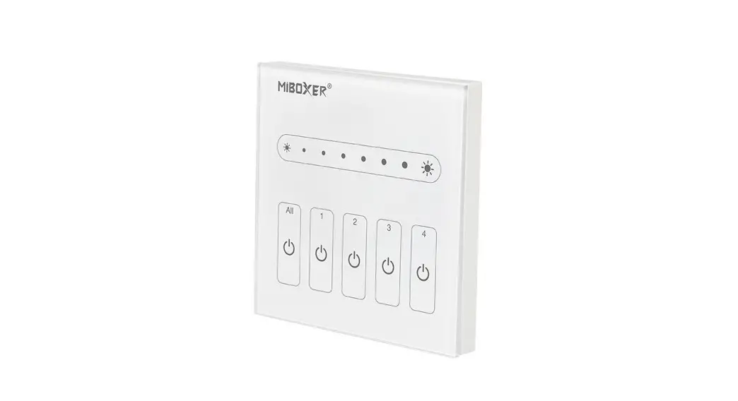
![]() DP1S Dali Touch Panel
DP1S Dali Touch Panel
Instruction Manual
Features
Adopt DALI standard protocol IEC62386. Powered by DALI bus, digital tube display, simple and quick function setting. It can control the ON/OFF, color, color temperature, saturation, and brightness of DALI lightings, and support scene saving and selection.
- Support DALI standard protocol IEC62386-102, 207, 209.
- Support DT8 type. Tc, XY coordinates, RGBWAF.
- Support 4 control modes: scene, grouping, unicast, and broadcast.
- Support ON/OFF, color, color temperature, saturation, and brightness control.
- Digital tube displays the address, group, scene. Function setting is simple and quick.
- Powered by DALI Bus.
- Touch control, sensitive touch.
Parameters
| Model No. | DP1S | DP2S | DP3S |
| Power Supply | DALI Power | DALI Power | DALI Power |
| DALI Bus Standard | IEC62386 | IEC62386 | IEC62386 |
| Output Signal | DALI Signal | DALI Signal | DALI Signal |
| Controlling Type | Dimming(DT6) | CCT(DT8 type: Tc) | RGB(DT8 type: xy coordinates) RGBW(DT8 type: RGBWAF) RGB+CCT(DT8 type: RGBWAF) |
| Standby Current | <4mA@16V | <4mA@16V | <4mA@16V |
| Working Temp. | -10~40°C | -10~40°C | -10~40°C |
| Weight | 145g | 145g | 145g |
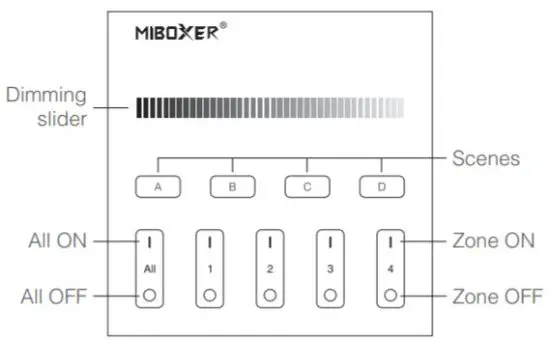
DALI Dimming Touch Panel (DT6) Model No.: DP1S
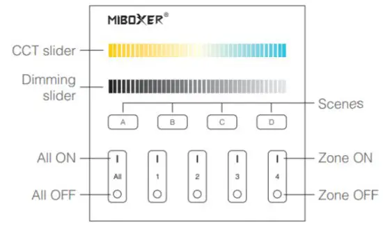
DALI Color Temp. Touch Panel (DT8) Model No.: DP2S
DALI 3 in 1 Touch Panel (DT8) Model No.: DP3S
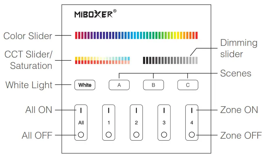
![]() Change lamp colors.
Change lamp colors.![]() Adjust color temperature.
Adjust color temperature.![]() Under white light mode, adjust color temperature.
Under white light mode, adjust color temperature.
Under color light mode, change lamp colors.![]() Adjust brightness(1%~100%).
Adjust brightness(1%~100%).![]() Short press to get white light mode.
Short press to get white light mode.![]() Short press A or B or C or D to select scene.
Short press A or B or C or D to select scene.
Long press A or B or C or D button to save the current light status to the Corresponding scene (see more on instruction 5).
Master ON: Short press to turn on all the lights under groups 1-4 on this panel.![]() Long press for 5 seconds to turn on the button sound.
Long press for 5 seconds to turn on the button sound.
Zone on (1-4): Short press to turn on all the lights in the group.
Master OFF: Short press to turn off all the lights under groups 1-4 on the panel.![]() Long press for 5 seconds to turn off the button sound.
Long press for 5 seconds to turn off the button sound.
Zone OFF (1-4): Short press to turn off all lights in the group.
 Indicator light: The group indicator light is always on, indicating that the group has been selected;
The indicators of the 4 groups are all on, indicating that all 4 groups are selected.
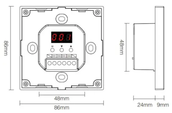
Function setting instruction
Digital dube display state instruction
Self-locking: If there is no operation for 5s, it will enter the locked state, and the digital tube will not display.
Unlocking: Long press the M button for 2s until the digital tube is highlighted, and the unlock is successful.
Control mode setting (Only DP3S have this function)
Under unlocked status, short press M button; until the digital tube displays DP3-DP5, press ▲ button or ▼ button to switch (RGB, RGBW, RGBCCT) 3 different control modes.
![]() RGB dimming control mode(DT8 type: x-y)
RGB dimming control mode(DT8 type: x-y)![]() RGBW dimming control mode(DT8 type: RGBWAF)
RGBW dimming control mode(DT8 type: RGBWAF)![]() RGBCCT dimming control mode(DT8 type: RGBWAF)
RGBCCT dimming control mode(DT8 type: RGBWAF)
DALI unicast address, group address, and broadcast address settings
Under unlocked status, short press M button,
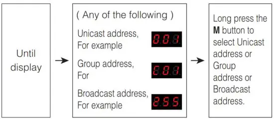
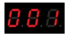
Unicast address:
When display (000-063): DALI panel is in unicast address mode. Short press ▲ or ▼ to set the start unicast address of DALI panel, long press can quickly adjust.
For example:
| Panel set a unicast address | Unicast addresses corresponding to the 4 groups | |||
| Zone-1 | Zone-2 | Zone-3 | Zone-4 | |
 | 001 | 002 | 003 | 004 |
 | 062 | 063 | 000 | 001 |
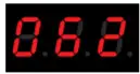
Group address:
When display (C00-C15): DALI panel is in group address mode. Short press the ▲ or ▼ to set the starting group address of the DALI panel, long press can quickly adjust.
For example:
| Panel set group address | Group addresses corresponding to the 4 groups | |||
| Zone-1 | Zone-2 | Zone-3 | Zone-4 | |
 | 01 | 02 | 03 | 04 |
 | 14 | 15 | 00 | 01 |
Scene setting
Under the unlocked state, short press the M button until the digital tube displays (E00-E15). Short press ▲ or ▼ to set the initial scene value of the DALI panel, long press for quick adjustment.
For example:
Setting to | Relative scene for (A B C D) button | ||
DP1S | DP2S | DP3S | |
 | A: Scenes 01 B: Scenes 02 C: Scenes 03 D: Scenes 04 | A: Scenes 01 B: Scenes 02 C: Scenes 03 D: Scenes 04 | A: Scenes 01 B: Scenes 02 C: Scenes 03 |
 | A: Scenes 14 B: Scenes 15 C: Scenes 00 D: Scenes 01 | A: Scenes 14 B: Scenes 15 C: Scenes 00 D: Scenes 01 | A: Scenes 14 B: Scenes 15 C: Scenes 00 |
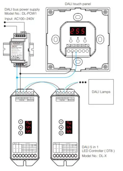
Connection Diagram
Installation / Dismantlement
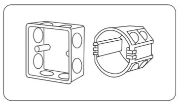 | 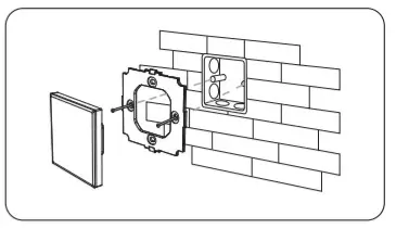 |
| Install the bottom case into the wall; Above are the standard bottom cases. | Fix the base on the bottom case with screw. |
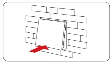 | 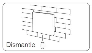 |
| Clip glass panel to the base. | Insert a screwdriver into the bayonet of the panel, pry it out to dismantle it. |
Attention
- The product shall be debugged and installed by professionals.
- Before switching on the power, please ensure that all wiring is correct, so as not to cause damage to the device.
- If there is faults, non-professional please do not repair without permission, otherwise, the device may be damaged.
 Made in China


