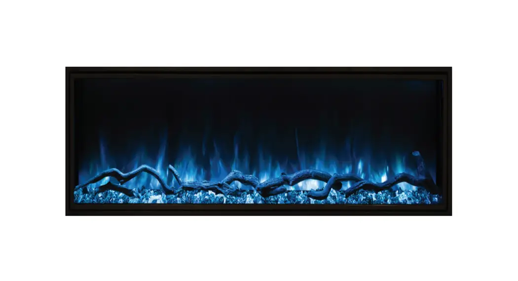
Landscape Pro Slim Series
LPS-4414 • LPS-5614 • LPS-6814 • LPS-8014 • LPS-9614INSTALLATION/OWNERS MANUAL
FOR USE IN UNITED STATES AND CANADA
SERIAL NUMBER:________________________________________
SAFETY INFORMATION AND OPERATIONS MANUALRead these instructions completely before beginning installation. Failure to follow them could cause a heater malfunction resulting in serious injury and/or property damage.
WARNING: All electric heaters have hot and arcing or sparking parts inside. Do not use it in areas where gasoline, paint or fl ammable liquids are or are stored.
This fireplace meets the construction and safety standards of H.U.D. for application in manufactured homes when installed according to these instructions.
INSTALLER: Leave this manual with the appliance.
CONSUMER: Retain this manual for future reference.
IMPORTANT INSTRUCTIONS
When using electrical heaters, basic precautions should always be followed to reduce the risk of fire, electric shock and injury to persons, including the following:
WARNING: Improper installation, adjustment, alteration, service or maintenance can cause injury or property damage. Refer to this manual. For assistance or additional information, consult a qualifi ed installer.
CAUTION: Do not expose the heater to the elements (such as rain, etc). Do not place clothing or other flammable material on or near firebox. Never place any objects on the fi replace. Carefully supervise young children when they are in the room with fi replace. Fireplace becomes very hot when running. Keep children and adults away from hot surfaces to avoid burns or clothing ignition. Fireplace will remain hot for a time after shutdown. Allow surfaces to cool before touching.![]() CAUTION: In order to avoid overheating, do not cover the heater.
CAUTION: In order to avoid overheating, do not cover the heater.
- Read all instructions before installing or using this heater.
- This heater is hot when in use. To avoid burns, do not let bare skin touch hot surfaces. Keep combustible materials, such as furniture, pillows, bedding, papers, clothes, and curtains at least 3 feet (0.9m) from the front of the heater and keep them away from the sides and rear.
- Extreme caution is necessary when any heater is used by or near children or disabled people and whenever the heater is left operating and unattended.
- Do not operate any heater after it malfunctions, has been dropped, or damaged in any manner. Disconnect power at service panel and have heater inspected by an authorized technician or a reputable electrician before using.
- Do not use outdoors.
- To disconnect heater, turn controls to off and turn off power to heater circuit at main disconnect panel.
- Do not insert or allow foreign objects to enter any ventilation or exhaust opening as this may cause an electric shock or fi re, or damage the heater.
- To prevent a possible fi re, do not block air intakes or exhaust in any manner.
- A heater has hot and arcing or sparking parts inside. Do not use it in areas where gasoline, paint or fl ammable vapors or liquids are used or stored.
- Use this heater only as described in this manual. Any other use not recommended by the manufacturer may cause fi re, electric shock or injury to persons.
- SAVE THESE INSTRUCTIONS
USER INSTRUCTIONS
POWER DATA
| LPS-4414 | LPS-5614 | LPS-6814 | LPS-8014 | LPS-9614 | |
| Voltz/HZ Amps | AC 120V 60Hz 14 Amps | AC 120V 60Hz 14 Amps | AC 120V 60Hz 14 Amps | AC 120V 60Hz 14 Amps | AC 120V 60Hz 14 Amps |
| Heater | AC 120V 1500W | AC 120V 1500W | AC 120V 1500W | AC 120V 1500W | AC 120V 1500W |
| Lamps | LED DC 12V | LED DC 12V | LED DC 12V | LED DC 12V | LED DC 12V |
| Rotor Motor | AC120V/60Hz 40mA 3.7W 18/15RPM CCW | AC120V/60Hz 40mA 3.7W 18/15RPM CCW | AC120V/60Hz 40mA 3.7W 18/15RPM CCW | AC120V/60Hz 40mA 3.7W 18/15RPM CCW | AC120V/60Hz 40mA 3.7W 18/15RPM CCW |
| Shipping Size | 47 %” x 26 %” x81/4″ | 59 ‘A” x 26 %” x81/4″ | 71 ‘A” x 26 %” x8%” | 83 1/2″ x 26 %” x8%” | 99 1/2″ x 26 %” x8%” |
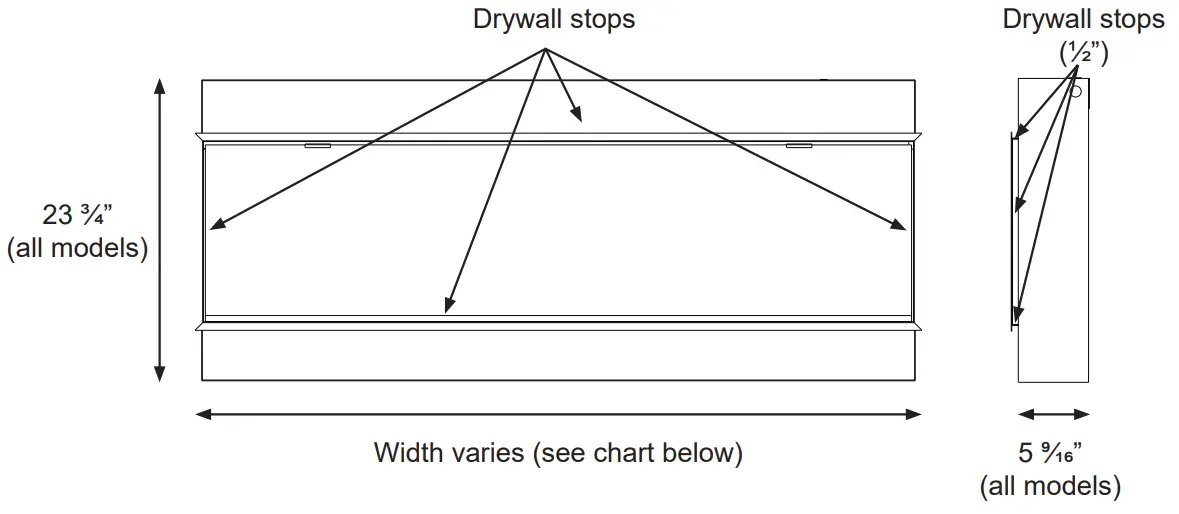
PRODUCT GUIDE
| Model | Viewing Area | Firebox Dimensions | Framing Dimensions |
| LPS-4414 | 43 ³⁄” W x 14” H | 44 ¹⁄” W x 23 ³⁄” H x 5 ⁹⁄” D | 44 ¹⁄” W x 24 ¹⁄” H x 6” D |
| LPS-5614 | 55 ³⁄” W x 14” H | 56 ⁵⁄” W x 23 ³⁄” H x 5 ⁹⁄” D | 56 ¹⁄” W x 24 ¹⁄” H x 6” D |
| LPS-6814 | 67 ³⁄” W x 14” H | 68 ⁵⁄” W x 23 ³⁄” H x 5 ⁹⁄” D | 68 ¹⁄” W x 24 ¹⁄” H x 6” D |
| LPS-8014 | 79 ³⁄” W x 14” H | 80 ⁵⁄” W x 23 ³⁄” H x 5 ⁹⁄” D | 80 ¹⁄” W x 24 ¹⁄” H x 6” D |
| LPS-9614 | 95 ³⁄” W x 14” H | 96 ⁵⁄” W x 23 ³⁄” H x 5 ⁹⁄” D | 96 ¹⁄” W x 24 ¹⁄” H x 6” D |
INSTALLATION
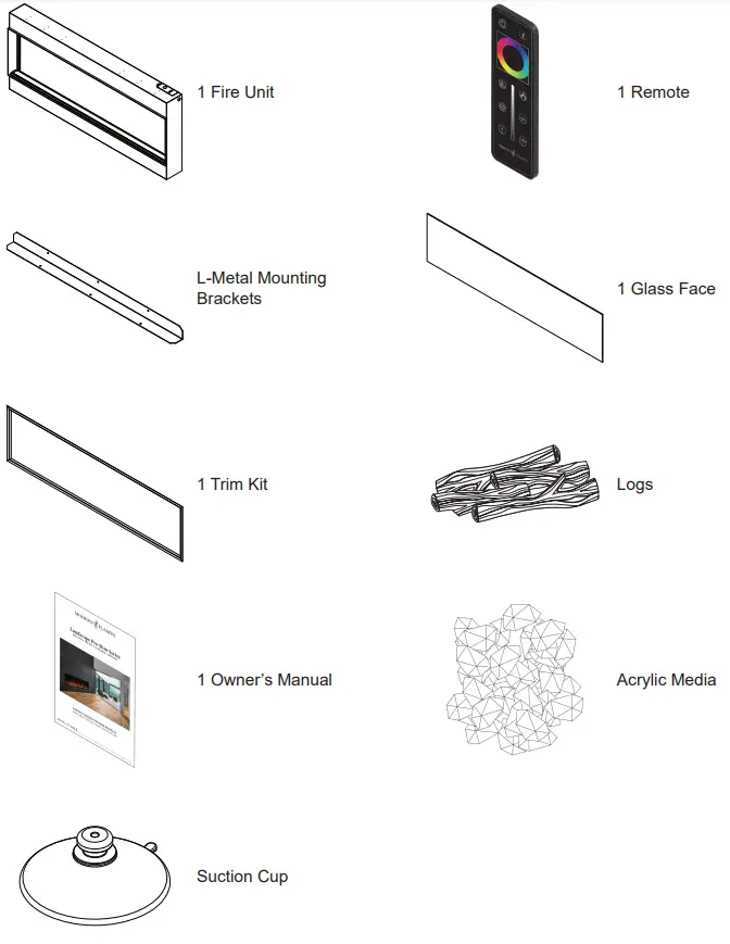
BOX CONTENTS
WARNING: If the information in these instructions is not followed exactly, a fire or explosion may result causing property damage, personal injury or death.
WARNING – RISK OF FIRE! To prevent a possible fire, do not block air intake or exhaust in any manner. Do not use on soft surfaces where openings may become blocked.
WARNING – RISK OF FIRE!
Do not blow or place insulation against the firebox.
To reduce the risk of fi re do not store or use gasoline or other fl ammable vapors in the vicinity of this or any other heater.
CAUTION: Keep combustible materials, such as furniture, pillows, bedding, papers, clothes and curtains at least 3 feet (0.9m) from the front of the heater and keep them away from the sides and rear.
CAUTION: Wear gloves and safety glasses for protection during installation and maintenance.
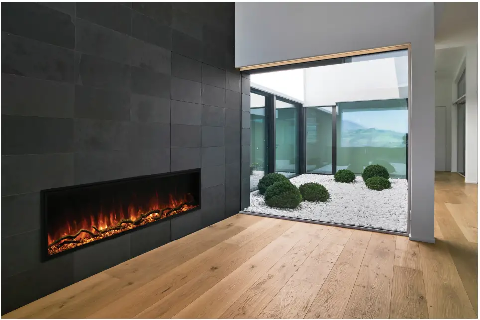
Installing fireplace
Select a suitable location that is not susceptible to moisture and is a safe distance from drapes, furniture and high traffic areas. A qualified electrician should add a dedicated flexible 20 amp 120 volt circuit per local building codes.
Note: Follow all national and local electrical codes.
This fireplace can be installed fully recessed or half recessed.
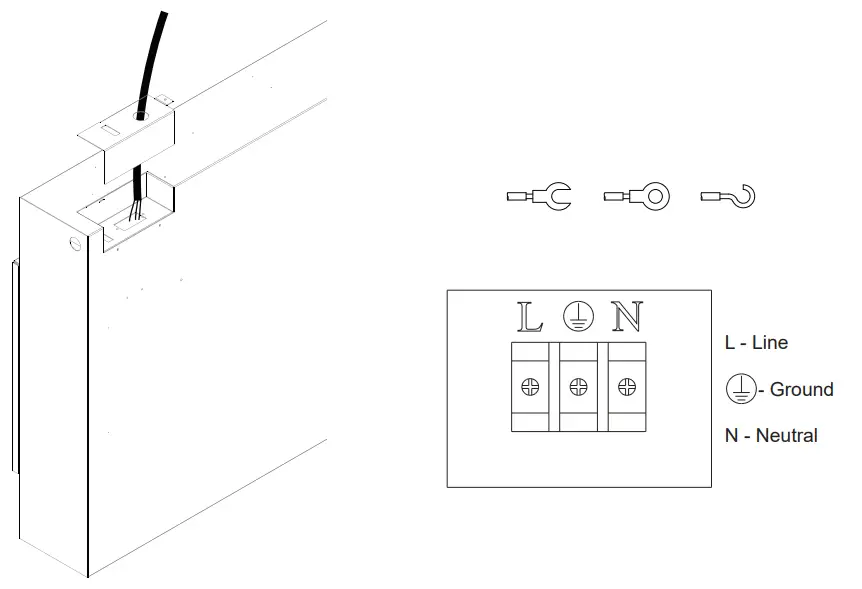
To prepare for installation, connect the hard wire to the terminal block according to the diagram below.
Choose any connector type according to local building code.
To be performed by a qualifi ed electrician according to local building codes.
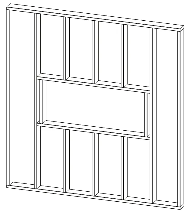
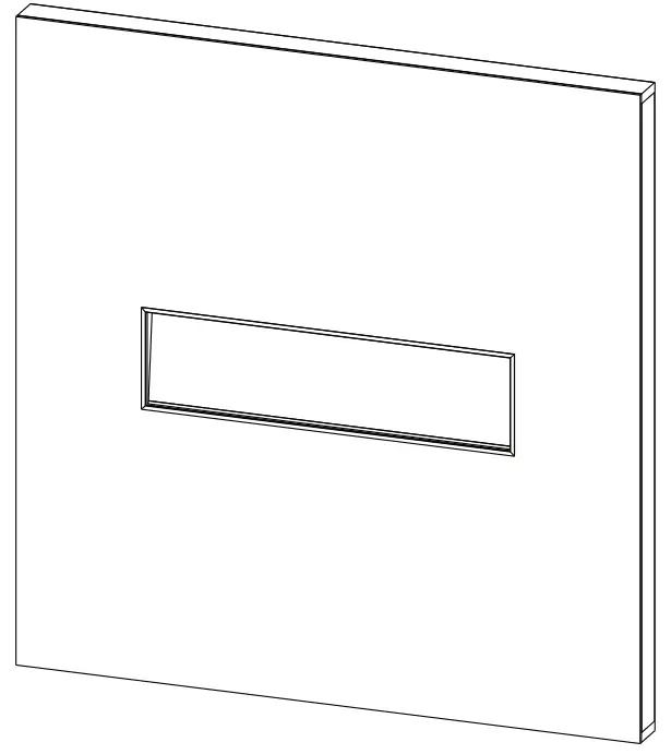
Fully recessed installation
| Model | W | H | D |
| LPSA414 | 44 ⅛” | 24⅛” | 6″ |
| LPS-5614 | 56 ½” | 24 ⅛” | 6″ |
| LPS-6814 | 68½” | 24⅛” | 6″ |
| LPS-8014 | 80½” | 24 ⅛” | 6″ |
| LPS-9614 | 96½” | 24 ⅛” | 6″ |
- This installation is optimized for a 2×6 framed wall. Prepare the framed opening according to the chart above. *Provide appropriate dedicated circuit for hardwire install at the top right of framed opening.

- Install L Metal Nailing Flanges to the top and bottom of the fi re unit.
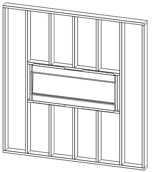
- Install the fi re unit in the framed opening with a minimum 1 ¼ drywall screws to secure the unit.

- Mask the exposed fi re unit during the drywall process. Install drywall to the drywall stops on the perimeter of the fi re box. For more information on the drywall stops see the Product Guide on page 4. Decorate as desired.
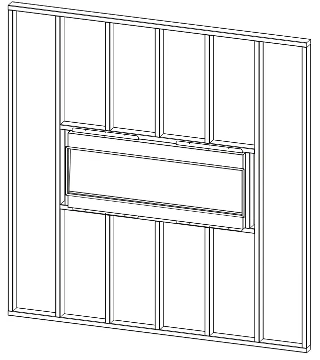
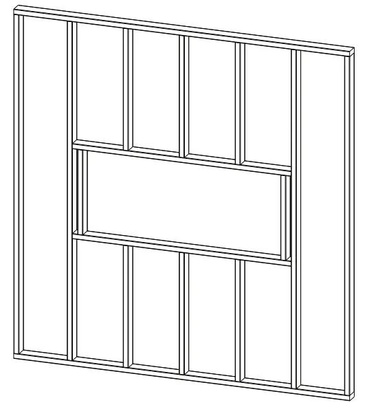
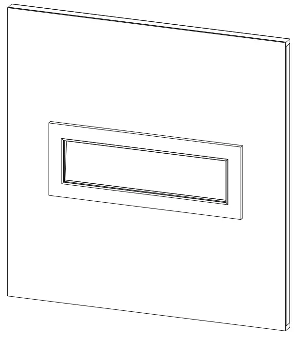
Half recessed installation
- This installation is optimized for a 2×4 framed wall. Prepare the framed opening according to the chart on page 7. *Provide appropriate dedicated circuit for hardwire install at the top right of framed opening.

- Install L Metal Nailing Flanges to the fi replace.
- Install the fi re unit in the framed opening with a minimum 1 ¼ drywall screws to secure the unit.

- Mask the exposed fi re unit during the drywall process. Install drywall to the perimeter of the fi re box. The unit can be covered with a custom facade. Decorate as desired.
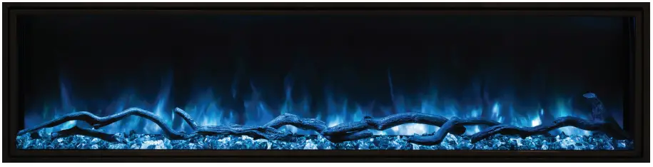
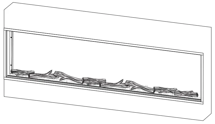
Installing Media and Front Glass
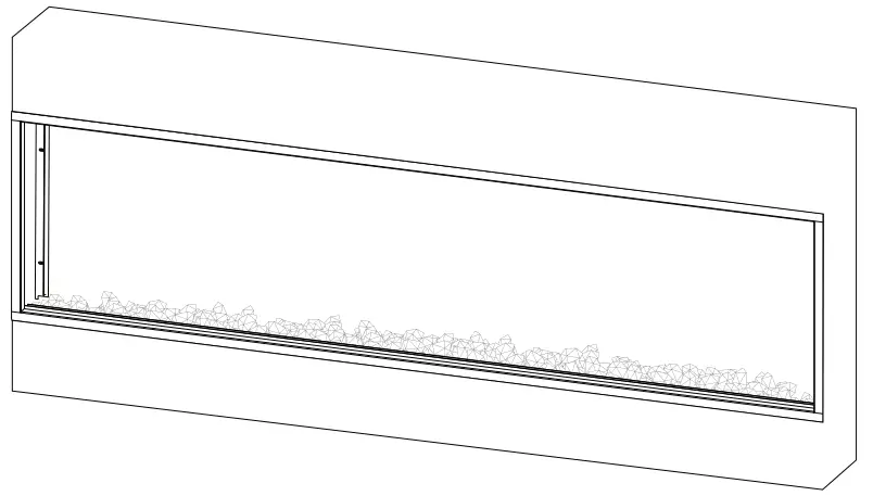
- Before installing the front glass, evenly spread out the acrylic crystals along the ember bed.

- Place the logs on top of the acrylic crystals.

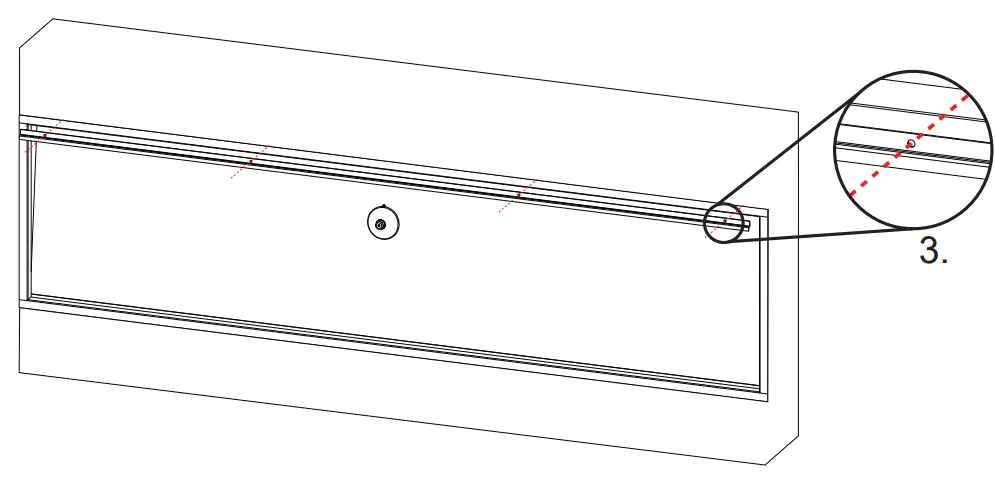
- The front glass can now be installed using the included suction cup. After placing the front glass it can be secured with screws.
OPERATION
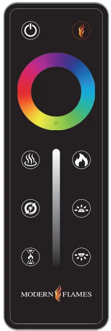
The unit has a main power switch just in front of the glass on the top right hand side. A hand-held remote is included.![]()
Power This will cycle the machine on and off . Upon cycling power on, the machine will return to the settings it had when it was cycled off . ![]()
Reset If the fi replace is on, this button will act as a reset and bring all colors back to the default Modern Flames’ signature color. ![]()
Heat This will cycle the heater between high, low and off . ![]()
Fade All zones of the fi replace will cycle through various demo modes – 7 & 3 color gradient/fade, 7 & 3 color jump, red/green/ blue gradient. ![]()
Sync Pressing the sync button will change all the colors of the fi replace (Flame, Ember Bed and Downlight) to match the current color of the flame setting. ![]()
Flame This is a zone setting. Touching this button will allow you to change the color and brightness of the flame by using the color wheel and brightness slider. ![]()
Ember Bed This is a zone setting that controls the color and brightness of the ember bed. ![]()
Downlight This is a zone setting that controls the color and brightness of the downlight. ![]()
Color Wheel This will cycle the selected zone through the colors of the color spectrum. ![]()
Brightness Slider This will adjust the brightness of the selected zone.
Pairing remote/wall mounted touch control:
- With the fi replace ON press and hold the Power button for about 3 seconds until you hear the buzzer sound twice and the power indicators begin to fl ash.
- Within 5 seconds on the hand held remote or wall touch control press the Power button repeatedly until the buzzer sounds again and the indicators fl ash acknowledging that it has paired. You may also hear another buzzer and the pair is now completed.
• Pairing must be done within 5 seconds or the fi replace will time out of pairing mode.
• To clear any paired remotes from the unit, locate then press and hold the reset button for 3 seconds.
You should hear a buzzer letting you know the codes have been cleared so you can now pair a new remote or wall touch control. (The reset is located next to the manual controls and can be pressed with a paper clip.)
Power indicator lights for wall switch as well as upper right corner of the main unit

When the switch turns on, this orange pilot lamp turns on. It shows the fi re is energized.

The status light above shows that the power is on and the heater is on low.

The status light above shows that the power is on and the heater is on high.
Manual Controls
The unit has manual controls located next to the power switch, just in front of the glass on the top right side.
Power
Turns unit on/offHeat
Cycles heat low/ high/offColor
Changes all fireplace colors
togetherReset
Resets unit
MAINTENANCE
SERVICE PARTSITEM PHOTO DESCRIPTION MF-PRO-PCB 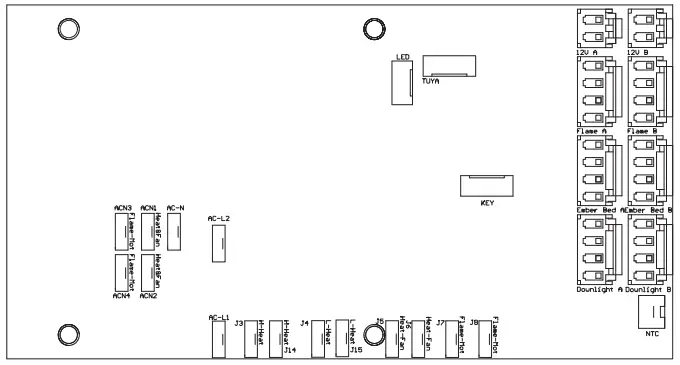
PRINTED CIRCUIT BOARD CONTROLS LOW VOLTAGE AND HIGH VOLTAGE FUNCTIONS AND TRANSFORMER MF-PRO-WIFI 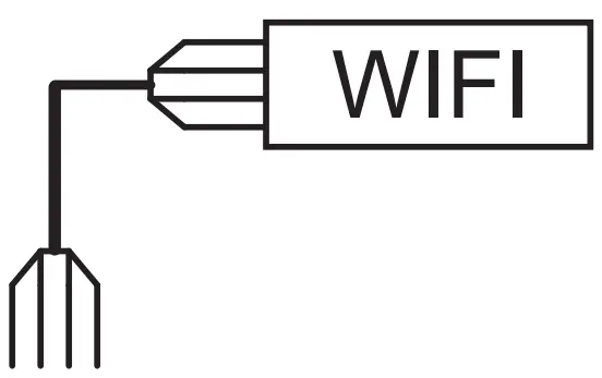
WIFI BOARD MF-PRO-HF 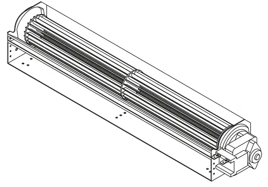
HEATER FAN 120 V MF-PRO-PTC 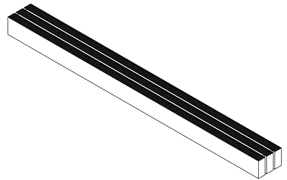
PTC HEATER 120V 750/1500 WATTS MFSM120 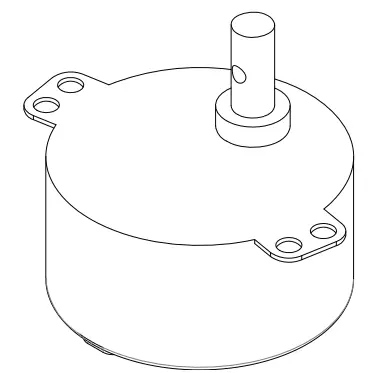
SPINDLE MOTOR 120 V 50-60 HZ MF-PRO-RC 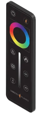
PRO SERIES RF REMOTE CONTROL MF-PRO-WTC 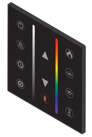
OPTIONAL
WALL MOUNTED TOUCH CONTROL ASSEMBLYMF-PRO-TB 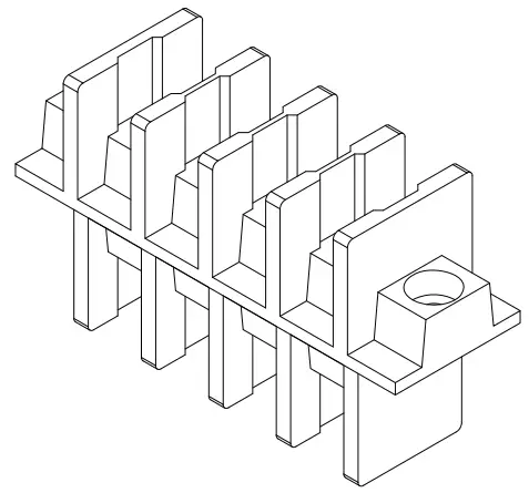
TERMINAL BLOCK 120/240 V MF-PRO-MTC 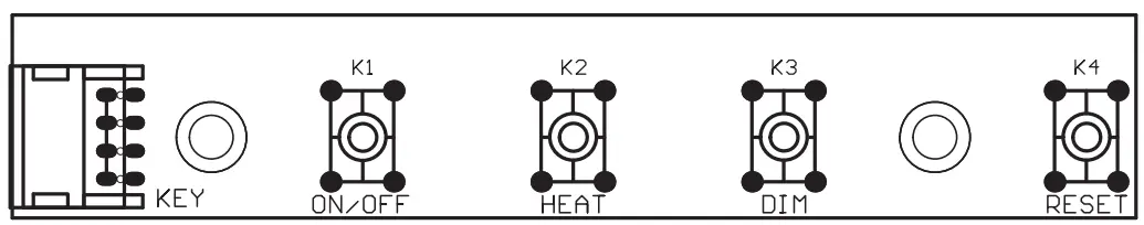
MANUAL TOUCH CONTROL BOARD MFPS2 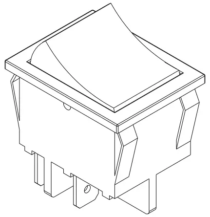
20 AMP POWER SWITCH ITEM PHOTO DESCRIPTION MF-PRO-PIB 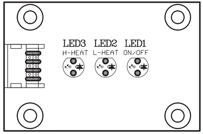
POWER INDICATOR BOARD MF-PRO-NTC 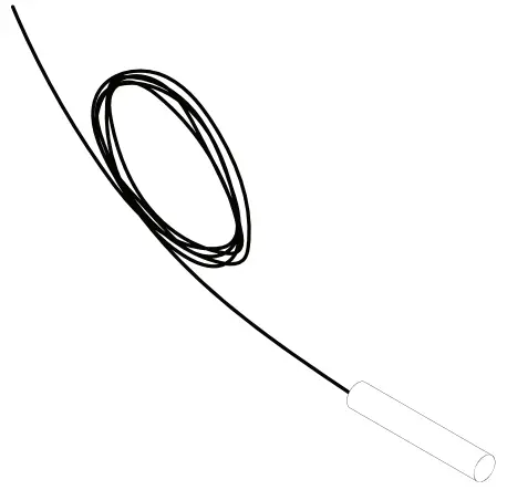
THERMOSTAT SENSOR MF-LPS-TK-44
MF-LPS-TK-56
MF-LPS-TK-68
MF-LPS-TK-80
MF-LPS-TK-96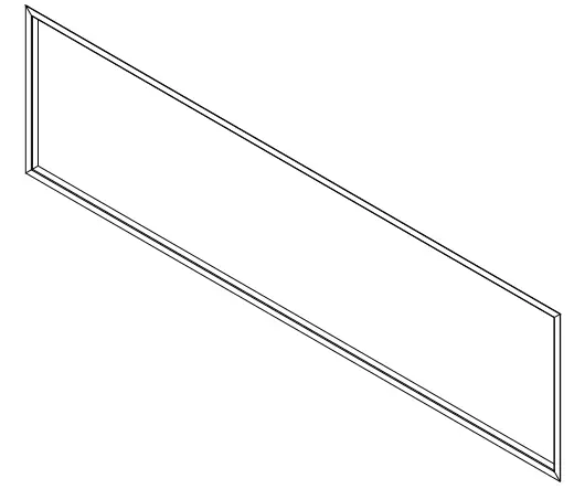
TRIM KIT MF-LPS-F/LED-44
MF-LPS-F/LED-56
MF-LPS-F/LED-68
MF-LPS-F/LED-80
MF-LPS-F/LED-96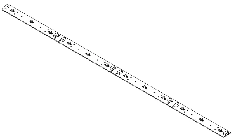
RGB FLAME LED BAR MF-LPS-EB/DL-44
MF-LPS-EB/DL-56
MF-LPS-EB/DL-68
MF-LPS-EB/DL-80
MF-LPS-EB/DL-96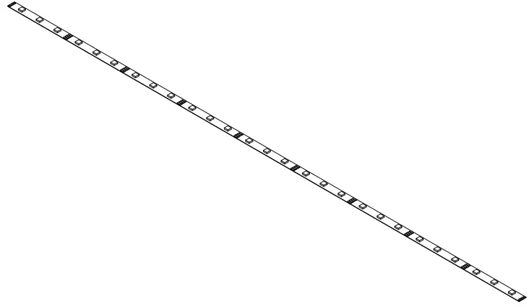
RGB EMBER BED/DOWNLIGHT LED STRIP MF-LPS-SR-44
MF-LPS-SR-56
MF-LPS-SR-68
MF-LPS-SR-80
MF-LPS-SR-96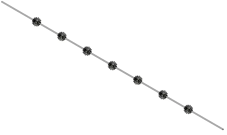
SPINDLE ROD FOR FLAME OR EMBER BED MF-LPS-GF-44
MF-LPS-GF-56
MF-LPS-GF-68
MF-LPS-GF-80
MF-LPS-GF-96
FRONT GLASS MF-LPS-PP-44
MF-LPS-PP-56
MF-LPS-PP-68
MF-LPS-PP-80
MF-LPS-PP-96POLY SCREEN
TROUBLESHOOTING
| Problem | Possible Cause | Corrective Action |
| Nothing comes on (touch screen, etc.) | A. Breaker tripped or circuit has no power | A. Reset breaker, test circuit for power, check power switch |
| B. Internal component is frozen and needs to be reset | B.Turn power off at the main breaker for 60 seconds. Turn power back on. | |
| C.Loose connection | C. Inspect wiring for loose or damaged connection | |
| D. Defective component | D. Replace motherboard. touch control or power switch | |
| Touch Screen Comes on – thennothing | A. Not operating touch control properly with finger | A.Press flat part of finger firmly on the touch screen and apply moderate pressure |
| B Loose connection on motherboard | B.Check functions with remote control. If functional, check connections on motherboard | |
| C.Motherboard is defective | C. Replace Motherboard | |
| Fireplace turns off and will not turn back on | A. Fireplace has overheated and safety disc has snapped or circuit breaker has tripped | -A Turn. the main breaker to theoff” position for 60 seconds. Next flip the breaker back into the on position. |
| Can operate fireplace functions with manual controls but not remote control | A. Low Batteries | A. Replace batteries in remote control with – CR2025 |
| B. Remote not paired properly | B.With the fireplace ON press and hold the Power button for about 3 seconds until you hear the buzzer sound twice and the power indicators begin to flash. Within 5 seconds on the hand held remote or wall touch control press the Power button repeatedly until the buzzer sounds again and the indicators flash acknowledging that it has paired. You may also hear another buzzer and the pair is now completed. | |
| C.Remote control defective | C. Replace remote control | |
| Heater does not provide heat when on | A. Wiring is loose | A. Disconnect unit from power source and inspect for loose connections |
| B. Snap disc tripped | B.Turn off for 5 minutes to reset | |
| C.Heater core is defective | C. Replace Heater Core |
| Problem | Possible Cause | Corrective Action |
| Flame is not visible when unit is turned on | A. Wiring is loose | A. Disconnect unit from power source and inspect for loose connections |
| B. LEDs defective | B.Replace LEDs | |
| C.Motherboard is defective | C. Replace motherboard | |
| Fireplace lights up but there is no flame image or flame image frozen | A. Wiring for motor is loose | A. Disconnect unit from power source and inspect for loose connections from motor |
| B. Spindle rod came loose | B.Reconnect spindle rod | |
| C.Motor is defective | C. Replace motor | |
| Fireplace is squeaking when flame image is on | A. Fireplace spindle/rod is contacting to metal | A. Apply lithium grease or any standard grease to contacts with rod and metal |
| B. Motor is defective | B. Replace motor |
FREQUENTLY ASKED QUESTIONS
A. Long press on the up and down arrows on the fire unit to toggle between Fahrenheit and Celsius.
A. Optimal distance for the remote control is maximum 20 feet.
A. Yes.
A. No. Please review the entire safety chapter before installing this fi replace.
A. Yes.
A. 1/2” or 5/8”, thinner is recommended for tile façade.
A. Annually, possibly more with heavy use.
A. No, only the actual remote requires batteries. The rest of the fi replace runs entirely off of the main power supply.
A. Turn power off at the breaker for 1 minute.
A. Optional wall control & Wi-Fi app instructions available for download on Modern Flames’ website, www.modernflames.com
CLEANING AND MAINTENANCE INSTRUCTIONS
There is very little maintenance involved with your electric fi replace. Please follow the few points below:
- On a semi-annual basis unplug the machine from it’s power source, wait for the heating element to cool and dust the fi re unit with a dry cloth. Be careful not to brush any wires that may be exposed as you do this.
- To clean the glass face of the fi replace simply use your desired glass cleaner with paper towels.
- To clean the air inlets/outlets, wipe with a soft cloth or the nozzle of a vacuum cleaner
- Dust can easily build up around the heater area inside the fi re unit, on the left and right sides. Take particular care to clean this area on a regular basis to prevent buildup.
- For long periods of inactivity, please unplug the fi replace and ensure the surrounding area remains dry.
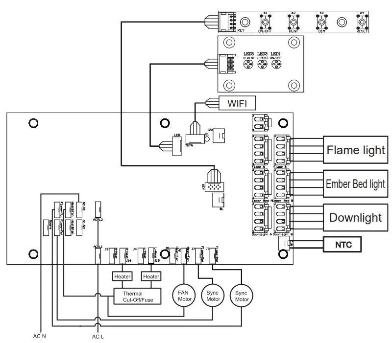
WIRING DIAGRAM
DO NOT RETURN TO STORE!
CALL US FIRST
For immediate help with installation, product information or
if your product arrives damaged, please call our toll free number at:
1-877-246-9353
(Monday – Friday, 8:00AM – 5:00PM, AZ Mountain Time)
Or email us at:
[email protected]
OUR STAFF IS READY TO PROVIDE ASSISTANCE
©2019www.modernflames.com
Please dispose of properly.


