OTTO 5R6=1 Socket Adapter
INSTRUCTIONS
- Please read this document carefully before using the product and observe the safety notices.
- Instruct the user in the safe use of the product.
- Please contact the manufacturer if you have questions about the product or in case of problems.
- Report each serious incident in connection with the product, in particular, a worsening of the state of health, to the manufacturer and to the relevant authority in your country.
- Please keep this document for your records.
Application and description
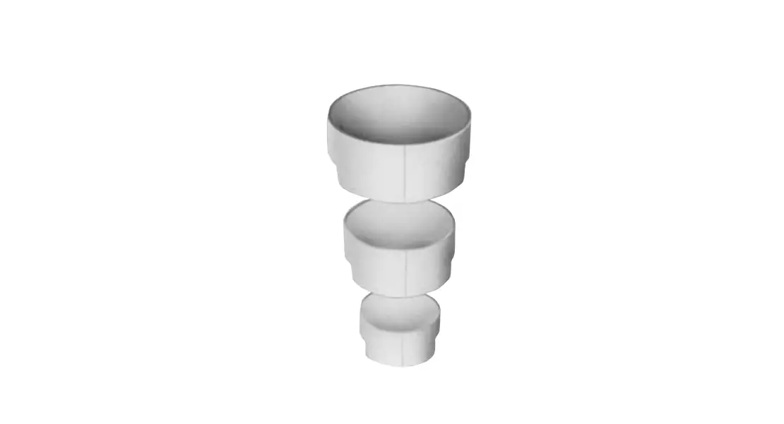
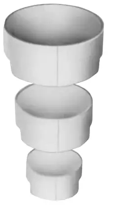
The 5R6 Modular Adapter is to be used exclusively for lower limb prosthetic fittings.
The Modular Adapter is suitable for transtibial [below-knee] and transfemoral (above-knee) prostheses. It is used to create a detachable connection between thermoplastic sockets or frames and the Modular System components.
Safety
General safety instructions
- CAUTION
Excessive strain on the product
Risk of injury due to breakage of load-bearing components- Use the product according to the specified area of application (Area of application).
- CAUTION
Unallowable combination of prosthetic components
Risk of injury due to breakage or deformation of the product- Only combine the product with prosthetic components that are approved for that purpose.
- Based on the instructions for use of the prosthetic components, verify that they may be combined with each other.
- CAUTION
Use under unallowable environmental conditions
Risk of injury due to damage to the product- Do not expose the product to unallowable environmental conditions.
- If the product has been exposed to unallowable environmental conditions, check it for damage.
- If damage is apparent or in case of doubt, do not continue using the product.
- Take suitable measures if required (e.g. cleaning, repair, replacement, inspection by the manufacturer or a specialist workshop etc.).
- CAUTION
Exceeding the service life
Risk of injury due to change in or loss of functionality and damage to the product- Ensure that the approved service life is not exceeded.
- CAUTION
Mechanical damage to the product
Risk of injury due to change in or loss of functionality- Use caution when working with the product.
- If the product is damaged, check it for proper function and readiness for use.
- In case of changes in or loss of functionality, do not continue using the product (see “Signs of changes in or loss of functionality during use” in this section).
- Take any necessary measures (e.g. repair, replacement, inspection by the manufacturer’s customer service, etc.).
Signs of changes in or loss of functionality during use
Among other factors, changes in functionality can be indicated by an alte-red gait pattern, a change in the positioning of the prosthetic components relative to each other and by the development of noises.
3 5Y14 Tool
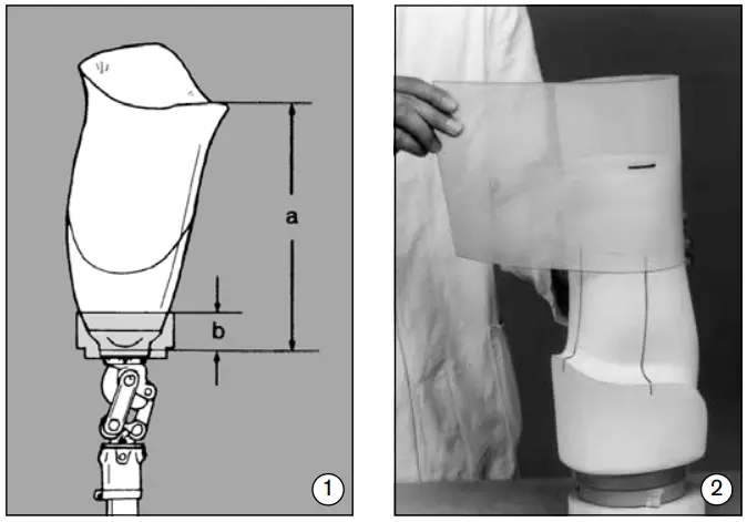
- The 5Y14 Tool is available in three sizes to correspond with the 5R6 Modu-lar Adapters. This tool makes it easier to accurately shape the distal end of the plaster extension of a plaster positive or vacuum-formed inner socket. To calculate the amount of space needed for fabrication, measure the distance from the ischial tuberosity to the lower edge of the modular adapter (a) and substract the tool depth (b): Size 1 = 50 mm, Size 2 = 45 mm, Size 3 = 35 mm (fig. 1).

- Draw reference lines on the positive to show the desired alignment. Use a piece of polyethylene sheet material to extend the model (inner socket). Pour plaster into the polyethylene sheet, filling to the marked height (corresponding to the upper edge of the tool). Square off the end of the extension with respect to the alignment lines (fig. 2).
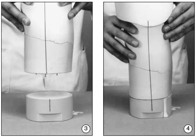
- For a stronger bond, drive a few brads into the hardened plaster insert. Coat the inner surface of the 5Y14 Tool with plaster parting agent cream. Then, fill in with thin plaster (fig. 3).

- Set the plaster model precisely on the tool and align using the plumb lines drawn on earlier (fig. 4).
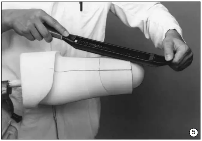
- Smooth the transition area on the model (fig. 5).

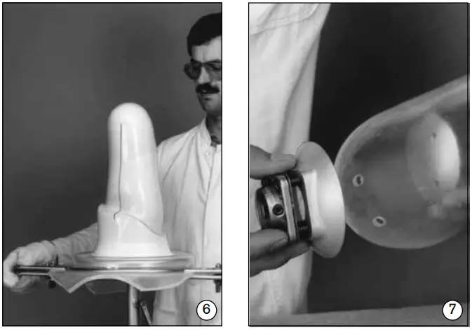
- Clamp the prepared model (inner socket) into the vacuum-forming tools. Pull the socket or outer support frame using a thermoplastic sheet (fig. 6).

- Determine the position of the socket, then drill four holes to mount the modular adapter to the socket (fig. 7).
Attention!
Both when mounting to the socket attachment block and when mounting a socket adapter, tighten the four screws in the following order:
- Tighten both countersunk head screws on the displacement (posterior) side with controlled torque to 12 Nm.
- Afterward, tighten the two countersunk head screws on the opposite side with controlled torque 12 Nm.
Use a 710D4 Torque Wrench!
Technical data
| Article number | 5R6=1 | 5R6=2 | 5R6=3 |
| Weight [g] | 160 | 135 | 115 |
| System height [mm] | 4 | 4 | 4 |
| Build height [mm] | 4 | 4 | 4 |
| Residual limb end circumference [mm] | Approx. 400 | Approx. 320 | Approx. 250 |
| Material | Aluminium | Aluminium | Aluminium |
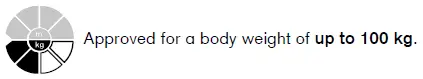
| Max. patient weight [kg] | 100 | 100 | 100 |
| Allowable environmental conditions |
| Temperature range for use: -10 °C to +60°C |
| Allowable relative humidity 0 % to 90 %, non-condensing |
| Unallowable environmental conditions |
| Mechanical vibrations or impacts |
| Perspiration, urine, fresh water, salt water, acids |
| Dust, sand, highly hygroscopic particles (e.g. talcum) |
Handling
Maintenance instructions
Note:
As a basic principle, all Ottobock modular adapters are subjected to tests involving three million load cycles. Depending on the amputee’s activity this corresponds to a service life of three to five years.
We recommend carrying out regular safety checks once a year.
Legal information
All legal conditions are subject to the respective national laws of the country of use and may vary accordingly.
Liability
The manufacturer will only assume liability if the product is used in accordance with the descriptions and instructions provided in this document. The manufacturer will not assume liability for damage caused by disregard of this document, particularly due to improper use or unauthorized modification of the product.
CE conformity
The product meets the requirements of Regulation (EU) 2017/745 on medical devices. The CE declaration of conformity can be downloaded from the manufacturer’s website.
Ottobock SE & Co. KGaA
Max-Näder-Straße 15 · 37115 Duderstadt/Germany T +49 5527 848-0 · F +49 5527 848-3360 [email protected] · www.ottobock.com


