FORLINX FET-MX9352-C SoM Industrial Board
Introduction
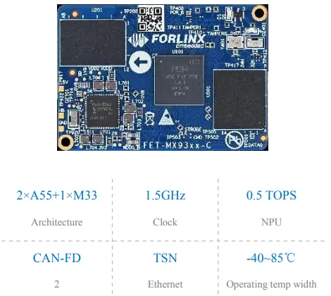
FET-MX9352-C SoM
FET-MX9352-C SoM is the world’s first system on module designed by Forlinx as a gold partner of NXP based on i.MX 9352 at the processor’s alpha phase. It contains two Cortex-A55 cores at speed up to 1.7GHz and one Cortex-M33 co-processor. 8x UART, 2x Ethernet(contains 1 TSN), 2x USB2.0, 2x CAN-FD and other common interfaces.It’s more advanced than i.MX6 and i.MX8, integrating NPU engine for deep learning accelerating. It has a compact appearance can fit various applications.
Features
- A core+ M core, multi-task processing with real-time control ;
- 0.5 TOPS Ethos U-65 microNPU for light AI applications;
- Dual Gigabit Ethernet with one enabled with TSN;
- One dual-lane MIPI-CSI;
- Various interfaces ready-to-use, excellent integrity of signal and power.;
- Advanced performance and cost efficient

SoM features:
| CPU | NXP i.MX9352 MPU: Cortex-A55 @1.5GHz MCU: Cortex-M33 @250 MHz NPU: 0.5 TOPS |
| RAM | 1GB LPDDR4 |
| ROM | 8GB eMMC |
| Voltage input | DC 5V |
| Operating temp | -40~85℃ |
| Package | Board-to-board connector(2*100-pin, 0.4mm pitch, combined height 1.5mm) |
| Interface | QTY | Spec. |
| LCD | 1 | Parallel RGB888, up to 1366×768p60 or 1280×800p60 |
| LVDS | 1 | Single 4-lane supports 720p60, up to 1366×768p60 or 1280×800p60 |
| MIPI-DSI | 1 | 1x 4-lane MIPI DSI Compatible with MIPI-DSI V1.2 and MIPI D-HPY V1.2 Pixel clock up to 200MHz, and pixel filling rate 140 MP/s, 24-bit Supports resolution of 1080p60 or 1920x 1200p60, each lane up to 1.5GHz |
| Ethernet | ≤2 | 2x RGMII with one supports TSN; Ethernet with TSN supports QoS, supports 802.1Qbv and 802.1Qbu Transmission rate 10/100/1000 Mbps, complies with IEEE 802.3 |
| UART | ≤8 | Baud rate up to 5Mbps |
| CAN-FD | ≤2 | Supports CAN-FD and CAN 2.0B |
| USB | ≤2 | Two USB2.0 controllers integrated with PHY |
| SD card slot | ≤1 | Complies with SD3.0; Supports SDR up to 200MHz and DDR up to 50MHz |
| SDIO | ≤1 | Complies with SDIO3.0 |
| SAI | ≤3 | SAI1 supports 2 lanes, SAI2 supports 4 lanes, and SAI3 supports 1 lane; Full-duplex serial supports frame synchronization, such as I2S, AC97, TDM and codec/ DSP |
| SPDIF | 1 | Supports original capturing mode; Supports L-PCM and IEC61937 forms |
| PDM | 1 | 24-bit, supports linear phase response and AOP MIC |
| MIPI-CSI | 1 | Compiles both MIPI CSI-2 V1.3 and MIPI D-PHY V1.2; Supports up to 2 RX data lanes (and 1 RX clock lane) Pixel clock up to 200MHz, pixel filling rate up to 150MP/s under rated voltage and over speed voltage; 80Mbps~1.5 Gbps under high-speed mode, and 10Mbps rating under low power mode; |
| SPI | ≤8 | Supports to configure master and slave modes |
| I2C | ≤8 | Rating up to 100Kbit/s in standard mode, and 400Kbit/s in fast-speed mode, 1000Kbit/ s in enhanced fast-speed mode, 3400Kbit/s in high-speed mode, and 5000Kbit/s in super fast speed mode. |
| I3C | ≤2 | Supports 400Kbit/s fast speed mode and 1000Kbit/s enhanced fast speed mode, backward compatible with I2C. |
| ADC | ≤4 | One 12-bit 4-lane 1MS/s ADC |
| JTAG | 1 | For M33 core debugging |
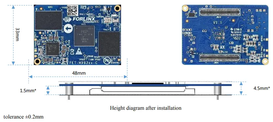
Exterior and dimensions
| OS version | Linux 5.15.52+Qt 6.3.2 |
| Firmware installation | • TF card
• USB OTG |
|
Linux5.10 | Interface | Function | Chipset | ||
| RGMII | Gigabit Ethernet | RTL8211FSI-CG | |||
| USB | WiFi/ BT | BL-M8723DU1 | |||
| USB | 4G modem | EC25/EC20 | |||
| USB | Serial/ RS485 | XR21V1414IM48 | |||
| USB | UVC camera | / | |||
| I2C | RTC | RTC8010/PCF8563 | |||
| MIPI-CSI | camera | OV5645 | |||
| SAI | Sound card | NAU88C22YG | |||
| MIPI-DSI | 7’’ MIPI-DSI | FIT-LCD7.0 V2.1MIPI with resolution of 1024x 600 | |||
| LVDS | 10.1’’ display | 1280x 800 | |||
| LCD-RGB888 | 7’’ LCD | FIT-LCD7.0V2.1 with resolution of 1024x 600 | |||
| SD card | TF card | General purpose | |||
| CAN/CAN-FD | General purpose | General purpose | |||
| GPIO | / | General purpose | |||
| ADC | 1 | General purpose | |||
| PWM | LCD backlight | / |
Provided technical files
| Linux5.15.52 | User manual, compiling guideline, kernel source code, file system, OS image, VM ubuntu image, SD card tool, USB OTG tool, QT demos and source code |
| Hardware | User manual, carrier board schematic, carrier board PCB(AD), datasheet, carrier board and SoM DXF files, pinmux sheet |
Order options
| Model | Core number | CPU speed | RAM | Flash | Working temp | Phase |
| FET-MX9352-C+151GSE8GIB11 | 2x A55 | [email protected] | 1GB | 8GB | -40~85℃ | sampling |
| FET-MX9352-C+171GSE8GCxxx | 2x A55 | [email protected] | 1GB | 8GB | 0~70℃ | scheduled |
| FET-MX9331-C+151GSE8GIxxx | 1x A55 | [email protected] | 1GB | 8GB | -40~85℃ | scheduled |
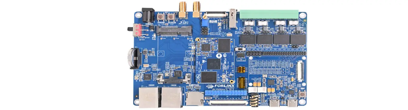
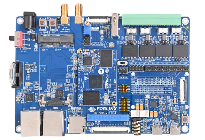
Development board/ kit

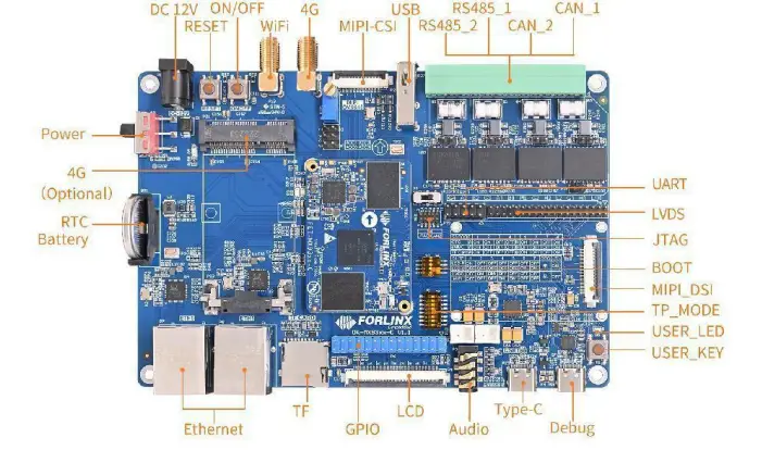
Carrier board features
| Peripheral | QTY | Spec. |
| LCD | 1 | RGB888 24-bit, up to 1366×768p60 or 1280×800p60 |
| LVDS | 1 | single 8-bit, up to 1366×768p60 or 1280×800p60 |
| MIPI-DSI | 1 | 4 lanes, up to 1920×1200p60 |
| TF card slot | 1 | For OS image flashing, complies with SD card 3.0 protocol |
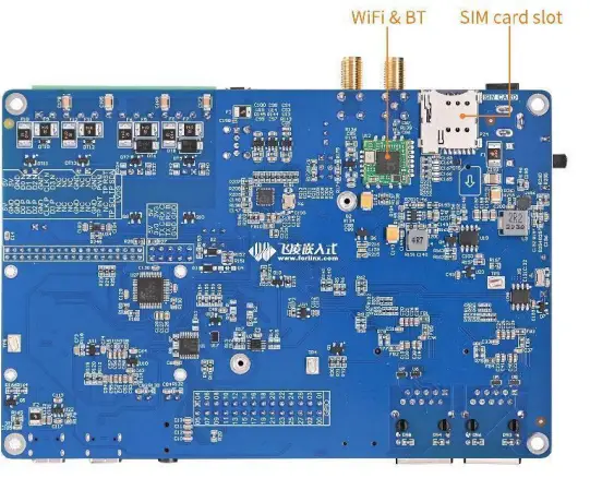
| 4G modem | 1 | Mini-PCIe slot, available for EC20 module with external antenna |
| Ethernet | 2 | 2x 10M/100M/1000M RJ45 connector, ENET1/ETH1 supports TSN |
| GPIO | 28 | dual-row pin headers, multiplexed with LCD |
| ADC | 4 | 12-bit ADC with sampling rate 1MS/s |
| CAN-FD | 2 | with static, surge and pulse protection circuits level 4, and Galvanic isolation complies with CAN2.0B |
| RS485 | 2 | with static, surge and pulse protection circuits level 4, and Galvanic isolation with automatic transceiving control |
| USB2.0 | 2 | USB1 by TYPE-C, can be used for OS image flashing; USB2 is expanded from HUB, circuited to 4G, WiFi /BT, USB to 4 serial, and USB-A female connector |
| UART | 2 | 3.3V TTL, by pin headers with pitch of 2.54mm |
| WiFi& BT | 1 | on-board BL-M8723DU, 2.4GWiFi, Bluetooth 2.1/4.2 |
| RTC | 1 | on-board RTC battery holder, for real-time updating |
| Audio | 1 | 1 four-part phone jack with dual-channel HP and MIC and 2 speaker jacks. |
| Camera | 1 | MIPI-CSI, fits OV5645 module |
| KEY | 3 | reset, power on/ off and user key |
| LED | 1 | user defined |
| GPIO | 9 | 9xGPIO(3.3V), 5V, 3.3V and 1.8V power by pin headers with pitch of 2.54mm |
| Debug | 1 | serial converted to USB for debug, TYPE-C connector |
| JTAG | 1 | 10-pin(2×5) headers with pitch of 2.0mm |
Copyright © 2007-2022 reserved by Forlinx Embedded Technology Co., Ltd.
[email protected]
www.forlinx.net


