
VENITEM L-LS-LSP HEMA

GENERAL DESCRIPTION
HEMA L is a low-consumption sounder with high-brightness LED flashing unit – anti-opening and anti-removal tamper – sound and timing programming – alarm counting – microprocessor self-test of: battery, speaker and drivers with dedicated anomaly negative output –programming of sounder trigger polarity – input for speaker block – permanent or momentary optical indication of alarm system ON/FF (arming/disarming) – electronic board protected against polarity inversion and tropicalized through a special resin tropicalization process against bad weather conditions and moisture. External cover and sounder base are in ABS while the internal cover is made of zinc-plated steel.
The tamper devices detecting removal, sounder opening, foam and shock are to be connected in series. In case of tamper attempt, they open the contact between the two TAMPER terminals thus triggering off the alarm.
HEMA LS: technical features as HEMA L with double micro switch anti-foam circuit provided of anti-shock technology against hard hits.
HEMA LSP: technical features as HEMA L with double micro switch anti-foam circuit provided of anti-shock technology against hard hits and anti-drilling device.
TECHNICAL FEATURES
| Voltage | Nominal battery recharge | 13.0 ± 13.8 Vdc |
| Minimum command | 4.1 Vdc | |
| Minimum supplying | 10 Vdc | |
| Max supplying | 15 Vdc | |
| Current | Max consumption from control panel (for battery recharge and sound) | 500 mA ± 100 mA |
| Battery consumption in alarm | 1.3 A +100/-300 mA | |
| Flashing unit consumption | 90 mA ± 10 mA | |
| Consumption in stand-by | 15 mA | |
| Consumption from control inputs | +0.5 mA @12 Vdc; -0.3 mA @ 0 Vdc | |
| Open collector | -10 mA Max | |
| Fundamental frequency | See CHART 6 | |
| Sound pressure | See DIAGRAM 1 | |
| Life of LED flashing light | 1,000,000 flashes | |
| Timings | 3 minutes, settable at 8 min | |
| Battery | Housing capacity | 12 Vdc 1.2 Ah or 12 Vdc 2.2 Ah max |
| Duration in stand-by | 120 hours using 12 Vdc 2.2 Ah model | |
| Control panel command | 2 or 3 wires | |
| Tamper switch | N.C. 0.2 A max; cover opening and sounder removal from wall | |
| Mechanic | ||
| Cover | Painted ABS | |
| Base | ABS | |
| Internal cover | Zinc-plated steel | |
| Flash cover | Polycarbonate | |
| Temperature conditions | from –25°C to +55°C | |
| Environmental class | Class IV | |
| IP protection | IP 44 | |
| Relative humidity condition | from 20% to 100% of RH | |
| Size | 330x210x110 (H x L x W) | |
| Weight | 1,957 gr | |
| Standards compliance | T031:2014 | |
| EN50131-4:2009 | ||
| Security | L and LS models | Grade 3 |
| LSP model | Grade 4 |
MOUNTING:
- Use the 6mm plugs to fix the siren on the wall; always check if the tamper works properly;
- Insert the connection cables through the holes located on the lower part of the sounder base;
- If necessary, modify the default settings by acting on the dipswitches as shown in the charts below;
- Connect battery and power supplying to the alarm control panel;
- Close both internal and external covers using the screws provided.
Battery must have UL94-HB flammability rate.
Power supplying must be of SELV type.
Attention: in order to avoid moisture formation inside the sounder, it is important to prevent air from flowing in the cable tray. To obtain such a result, once the sounder is connected, seal the hole using some silicon or any other filler type. This operation avoids the formation of moisture inside the sounder; condensation mostly appears in winter and it is usually caused by warm and humid air coming out of the wall where the sounder is installed and passing through the holes located on the sounder base. Condensation and moisture can affect the sounder which might not work properly.
CONNECTION SCHEMES
- FOUR-WIRE CONNECTION
Connect 13.8 Vdc supplying coming from control panel to the dedicated terminals:- RIC negative; +RIC positive; +C positive-missing trigger; RES negative trigger for flash reset.
Note: by default, DIPSWITCH N°2 is set in OFF position, POSITIVE-MISSING TRIGGER
- RIC negative; +RIC positive; +C positive-missing trigger; RES negative trigger for flash reset.
- THREE-WIRE CONNECTION
Connect 13.8 Vdc supplying coming from control panel to the dedicated terminals:- RIC negative; +RIC positive. (+C trigger must be jumped to +RIC ); RES negative trigger for flash reset.
Note: by default, DIPSWITCH N°2 is set in OFF N°6 OFF, POSITIVE-MISSING TRIGGER
- RIC negative; +RIC positive. (+C trigger must be jumped to +RIC ); RES negative trigger for flash reset.
- HEMA LSP MODEL WIRING
Connect 13.8 Volt supplying coming from control panel to the dedicated terminals:- RIC negative; +RIC positive; +C positive-missing trigger; RES negative trigger for flash reset.
Note: by default, DIPSWITCH N°2 is set in OFF position, POSITIVE-MISSING TRIGGER
Only in HEMA LSP model, terminal M9 must be jumpered to terminal M10 TAMPER A.P.
- RIC negative; +RIC positive; +C positive-missing trigger; RES negative trigger for flash reset.
- OPTICAL INDICATION OF SYSTEM STATUS (MOMENTARY OR PERMANENT ON-OFF)
- If a positive is given to terminal STI (System status) all LEDs of the flashing light make 3 flashes (ON);
- If the positive is removed, all LEDs light on steady for 5 seconds (OFF) and the complete sounder test is launched (remote test).
By default, DIPSWITCH N°4 is set in OFF position (MOMENTARY ON-OFF)
DIPSWITCH N°4 in ON position (MOMENTARY ON-OFF) and 1 LED keeping on flashing as long as positive tension = 0V is given to terminal STI.
- SOUNDER TIMING
By default, timing is 3 minutes (DIPSWITCH N°1 in OFF position) and it can be modified into 8 minutes. - TERMINAL 5 – NEGATIVE SOUND-BLOCK INPUT
It gives a 0V signal to terminal 5 thus activating the sound interruption trigger. - TERMINAL OUT ANM AND FAULTS LED
The microcontroller managing the sounder is able to check if recharge, battery, loudspeaker and drivers are working properly. In case of faults, the open collector output OUT ANM opens while the LED located on the sounder board shows the type of fault by making a certain number of flashes followed by a short pause (please see chart here below for FAULTS LED signalisation).
The microcontroller automatically performs every 4 hours the battery current test. Moreover, other tests are performed on regular basis. Usually, if the sounder is properly supplied, the faults output (terminal 7) remains at 0 Vdc (max consumption 50 mA). In case any of the tests performed fails, the faults output disconnects from the ground and becomes free. Moreover, the microprocessor is always under self-test and in case of failure or malfunctioning, it gives a free output with sound interruption.
To reset the fault appeared: eliminate the fault cause. Then:- (see scheme below): wait 10 seconds, let terminal n°4 (STI) free, take it to 12 Vdc, wait 10 seconds and let terminal n°4 free again. This procedure resets all faults;

- all faults are anyway reset after every alarm (+C), with the exception of those concerning the battery that are reset after 12 hours from battery restore (replacement). The sounder performs all tests again and therefore updates battery faults too.
At the first sounder supplying (13.8 Vdc or battery), anomalies automatically reset once the cause disappears; this makes the installation easier. After the first activation of the sounder, anomalies reset through a command to STI terminal or through +C.
To launch the remote test, see scheme here above. This action launches the test that lasts 60 seconds. During the test, the sounder verifies if it is working properly and provides signalization of any faults through the faults output (OUT ANM) and the faults LED as shown in CHART 1:
FAULTS below.
In case a fault occurs, the LEDs of the flashing light flash faster.
CHART 1: FAULTSFAULT TYPE LED
LD1Output
OUT ANMSpeaker interruption (test performed every 10 s) 1 FLASH OPEN No recharge voltage (recharge V < 12 Vdc) (test performed every 10 s) 2 FLASHES OPEN Battery not connected (test performed every 12 hours) 3 FLASHES OPEN Low battery (battery V < 10.5V) (test performed every 12 hours) 4 FLASHES OPEN Damaged battery – internal resistor over 3.5 Ohm (test performed every 12 hours) 5 FLASHES OPEN Speaker drivers failure (test performed every 10 s) 6 FLASHES OPEN No anomaly OFF 0V
- (see scheme below): wait 10 seconds, let terminal n°4 (STI) free, take it to 12 Vdc, wait 10 seconds and let terminal n°4 free again. This procedure resets all faults;
- CONNECTION OF MICRO SWITCH ANTI-OPENING AND ANTI-REMOVAL TAMPER
Connect the tamper line coming from control panel in series to the two wires of micro switch located on the sounder using the dedicated terminals TAMPER 8 and 9. - CONNECTION OF ANTI-FOAM (LS model)
Connect the two wires of the antifoam device in series to the micro switch and the tamper line coming from control panel. - CONNECTION OF ANTI-DRILLING (LSP model)
Connect TAMPER A.P. terminals in series to the anti-foam, the micro switch and the tamper line coming from control panel.
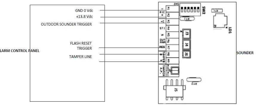
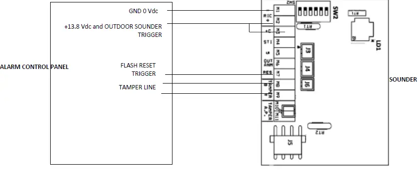
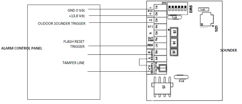

Diagram 1 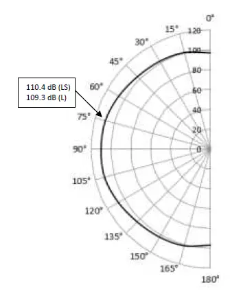
| HEMA LS DIP3 in ON position | |
| Angle | dB (A) @1m |
| 15° | 100.8 |
| 45° | 104.5 |
| 75° | 110.4 |
| 105° | 110.7 |
| 135° | 104.7 |
| 165° | 100.8 |
| HEMA L DIP3 in ON position | |
| Angle | dB (A) @1m |
| 15° | 100.9 |
| 45° | 103.4 |
| 75° | 109.3 |
| 105° | 110.1 |
| 135° | 104.0 |
| 165° | 101.2 |
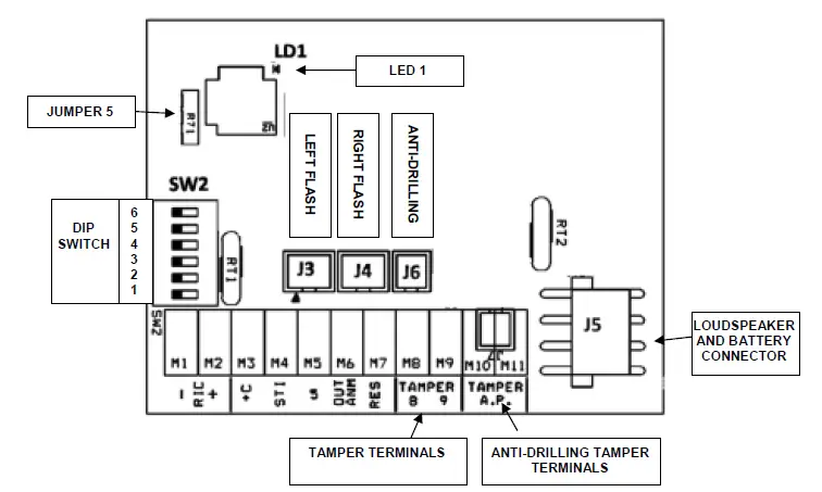
CONNECTION and SETTINGS
DIP SWITCHES SETTING
DIP switches can be moved only within the first 12 hours after the board is powered. After this period, DIP switches settings will be stored and any further switching will be useless.
By disconnecting battery and power supply, DIP switches will return to active for another 12 hours.
| Chart 2: dipswitches and jumpers | |
| DIP 1 | Alarm timing |
| DIP 2 | Polarity of alarm input +C |
| DIP 3 | Tone selection |
| DIP 4 | Alarm system STI (ON/OFF) notice setting |
| DIP 5 | Flash reset mode |
| DIP 6 | Alarm trigger mode +C |
| JUMPER 5 | Max daily alarms |
| Chart 3: wiring | |
| Terminals | Connections |
| -RIC (1) | Negative supplying 0 Vdc GND |
| +RIC (2) | Positive supplying +13.8 Vdc |
| +C (3) | Sounder control chart 5 |
| STI (4) | ON/OFF indication of alarm system status |
| 5 | Input for sound block |
| OUT ANM (6) | Fault output. Open collector, 0 Vdc = no anomaly |
| RES (7) | Flash reset |
| TAMPER (8) | Self-protection N.C. |
| TAMPER (9) | Self-protection N.C. |
| Chart 4: alarm timing | |
| DIP 1 | Alarm duration |
| OFF (default) | 3 minutes |
| ON | 8 minutes |
| Chart 5: Voltage reference for alarm input +C | |
| DIP 2 | Terminal +C |
| OFF (default) | Positive (12 Vdc) reference for Alarm [see DIP 6] |
| ON | Negative (0 Vdc) reference for Alarm [see DIP 6] |
| Chart 6: tone selection | ||
| DIP 3 | Tone | Frequency limits (Hz) |
| OFF (default) | Increasing-continuous-decreasing | 1,200 ÷ 1,750 |
| ON | Increasing-decreasing (NFC 48-265) | 1,400 ÷ 1,600 |
| Chart 7: Alarm system STI (ON/OFF) signalization setting | ||
| DIP 4 | Terminal 4 | Flash status (ON/OFF) |
| OFF (default) | +12 Vdc | All LEDs flash 3 times |
| Not connected or 0 Vdc | All LEDs remain steady on for 4 seconds then switch off | |
| ON | +12 Vdc | All LEDs flash 3 times and 1 LED keeps on flashing |
| Not connected or 0 Vdc | All LEDs remain steady on for 4 seconds then switch off | |
| Chart 8: flash reset mode | |
| DIP 5 | Flash behaviour – Terminals +C and RES |
| OFF (default) | Flash activates through +C trigger and deactivates through a negative signal to RES terminal (Flash reset) |
| ON | Flash activates through +C trigger and deactivates through +C trigger |
| Chart 9: Alarm trigger mode +C | ||
| DIP 6 | Terminal +C | Note |
| OFF (default) | Missing Reference | Alarm occurs by disconnecting the cable (see DIP 2) |
| ON | Giving Reference | Alarm occurs by connecting the cable (see DIP 2) |
| Chart 10: Max daily alarms | |
| JUMPER 5 | Number of alarms during 24 hrs after the first alarm |
| CONNECTED (default) | Infinite alarms |
| CUT | Restriction to 4 daily alarms (24 hours) of sound activation (STI resets the counter to zero) |
INSTALLATION SUGGESTIONS
In case the sounder does not work properly, check if the on-board LED flashes. If it flashes, check FAULTS CHART here above.
WARRANTY
All Venitem products are granted against factory or material defects. In order to improve design and quality of its products, Venitem reserves the right to modify the products without prior notice. All faulty or defective products must be returned to supplier.
Product manufactured in Italy
Venitem s.r.l.
via del Lavoro, 10
30030 – Salzano (VE) – ITALY Tel. (+39) 0415740374
Fax (+39) 0415740388
E-mail: [email protected]
website: www.venitem.com


