HONDA A 9 Clutch Gearshift Linkage Driver Gear
SERVICE INFORMATION
GENERAL
This section covers removal and installation of the clutch, primary drive gear, oil pump drive gear and gearshift linkage. These services can be performed with the engine installed in the frame.
SPECIFICATIONS
TORQUE VALUES
- Clutch lifter bolt 12 N·m (1.2 kgfm, 9 lbHt)
- Clutch center lock nut 74 N·m (7.5 kgf·m, 54 lbf·ft)
- Shift drum stopper arm bolt 12 N·m (1.2 km, 9 lb t)
- Gearshift return spring pin 25 N·m (2.5 kg-m, 18 ! bf-ft) Apply a locking agent to the threads
- Primary drive gear lock nut 53 N·m (5.4 kg-fm, 39 lbf·ft)
TOOLS
- Clutch center holder 07GMB – KT70101
- Gear holder 07724 – 0010200
- Lock nut wrench, 20 x 24 mm 07716 – 0020100
- Extension bar 07716 – 0020500 or equivalent commercially available in U.S.A.
RIGHT CRANKCASE COVER REMOVAL
- Drain the engine oil
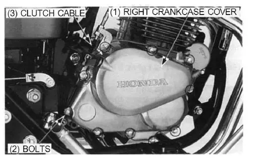
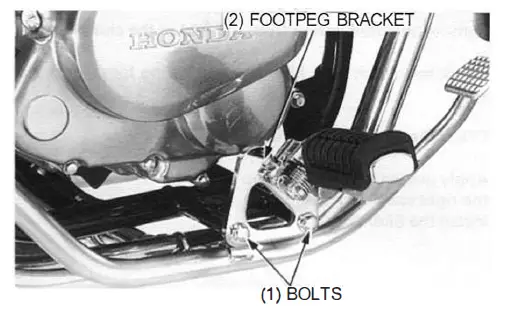
Remove the bolts and right footpeg bracket.
- Disconnect the clutch cable from the clutch arm. Remove the bolts and right crankcase cover.

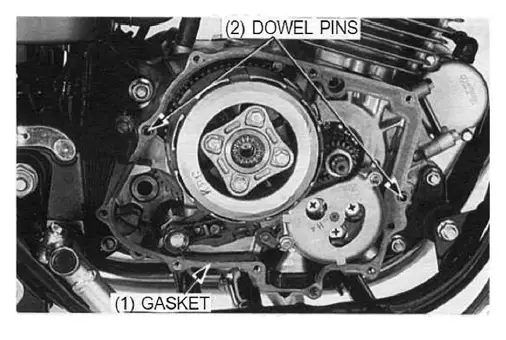
- Remove the gasket and dowel pins.

CLUTCH LIFTER REMOVAL/INSTALLATION
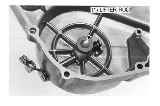
- Remove the clutch lifter rod.

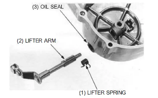
- Remove the lifter spring from the end of the clutch arm.
- Check the clutch arm, lifter rod and spring for wear or damage.
- Check the oil seal for damage.
- Apply grease to the oil seal lip and insert the clutch arm into the right crankcase cover.

- Install the lifter spring.
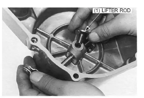
- Slightly turn the clutch arm clockwise and install the lifter rod into the right crankcase cover.

CLUTCH
REMOVAL
Remove the clutch lifter plate bolts, plate and clutch springs.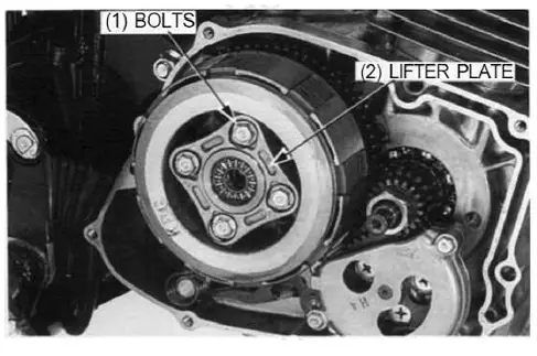
NOTE
Loosen the clutch lifter plate bolts in a crisscross pattern in 2 – 3 steps.
Unstake the clutch lock nut with a drill or grinder.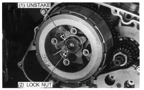
CAUTION
Be careful not to damage the mainshaft threads.
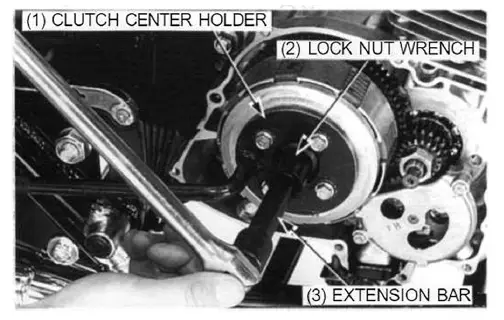
Remove the clutch center lock nut using the special tools.
TOOLS:
- Clutch center holder 07GMB – KT70101
- Lock nut wrench, 20 x 24 mm 07716 – 0020100
- Extension bar 07716 – 0020500 or equivalent commercially available in U.S.A.

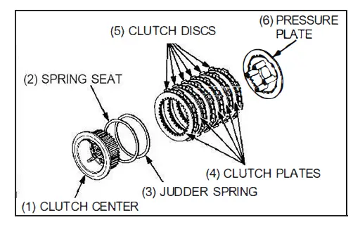
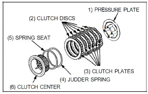
Remove the following:
- Clutch center
- Spring seat
- Judder spring
- Clutch discs and plates
- Pressure plate
- Spline washer
- Clutch outer
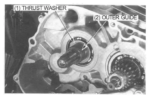
- Outer guide
- Thrust washer

INSPECTION
Clutch lifter bearing
Turn the lifter bearing rollers with your finger. The bearing should turn smoothly and freely witlhout excessive play.
If necessary replace the bearing.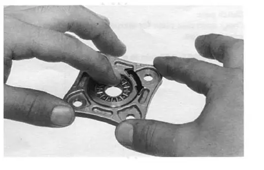
Clutch spring
Measure the clutch spring free length. SERVICE LIMIT: 36.0 mm (1.42 in)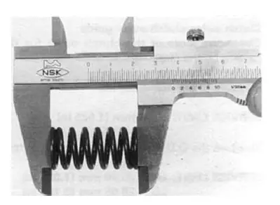
Clutch center
Check the grooves of the clutch center for damage or wear caused by the clutch plates.
Replace if necessary.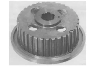
Clutch disc
Replace the clutch discs if they show signs of scoring or discoloration.
Measure the disc thickness of each disc.
SERVICE LIMIT: 2.6 mm (0.10 in)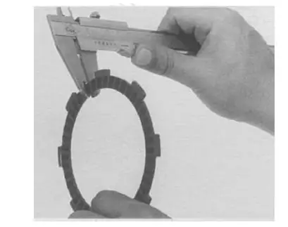
Clutch pate
Check each disc plate for warpage on a surface plate using a feeler gauge.
SERVICE LIMIT: 0.20 mm (0.008 in)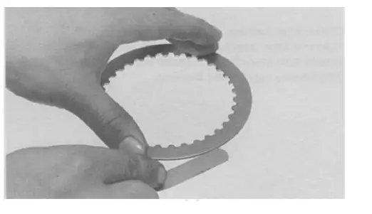
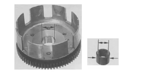
Clutch outer/clutch outer guide
Check the slots of the clutch outer for damage or wear caused by the clutch discs.
Replace if necessary.
Measure the clutch outer 1.0.
- SERVICE LIMIT: 26.04 mm (1.025 in)
- Measure the 0.0. and 1.0. of the clutch outer guide.
- SERVICE LIMIT: O.D.: 25.90 mm (1.0-20 in) I.D.: 20.05 mm (0.789 in)

installation

- Install the thrust washer and clutch outer guide onto the mains haft.

- Install the clutch outer and spline washer.

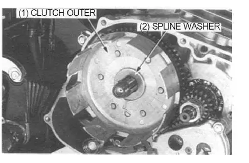
NOTE
Note the direction of the spline washer.
- Install the spring seat and judder spring onto the clutch center as shown.
- Assemble the clutch pressure plate, discs, plates and clutch center, and install them in the clutch outer.
- Coat new clutch discs with clean engine oil.
- Stack the discs and plates alternately.

NOTE
Note the direction of the judder spring.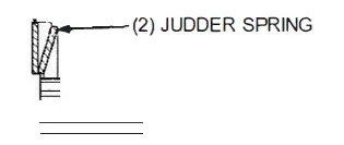
Stack the discs and plates alternately.
Install the lock washer with its “OUT SIDE” mark facing out.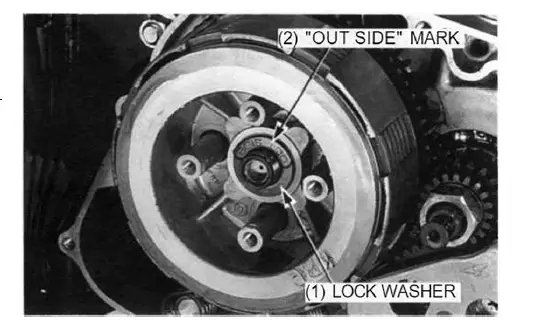
Attach the clutch center holder using the clutch lifter bolts. Install a new lock nut, then tighten it to the specified torque using the special tools.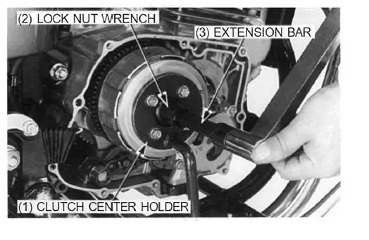
TOOLS:
- Clutch center holder 07GMB- KT70101
- Lock nut wrench, 20 x 24 mm 07716- 0020100
- Extension bar 07716 – 0020500 or eqlllivalent commercially available in U.S.A.
TORQUE: 74 N·m (7.5 kgf·m, 54 lbf-ft)
Stake the end of the lock nut into the groove of the mainshaft with a punch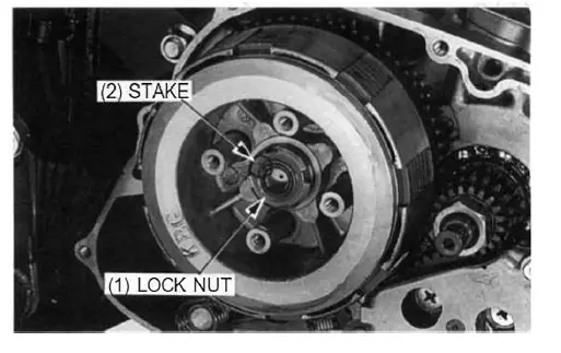
- Install the clutch springs and lifter plate.
- Install and tighten the lifter plate bolts to the specified torque.
NOTE
Tighten the lifter plate bolts in a crisscross pattern in 2 – 3 steps.
TORQUE: 10 N·m (1.0 kgf·m, 7 lbMt)
- Install the lifter plate bearing if it was removed.
- Install the right crankcase cover (page 9-12).
PRIMARY AND OIL PUMP DRIVE GEARS
REMOVAL
- Remove the right crankcase cover (page 9-3).
- Remove the oil pump (page 4-2).
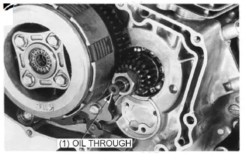
- Remove the oil through and spring from the crankshaft.

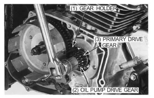
- Attach the gear holder between the primary drive and driven gear as shown.
TOOL:
Gear holder 07724 – 0010200
- Remove the lock nut and washer.
- Remove the clutch assembly (page 9-4).
- Remove the oil pump drive gear and primary drive gear

INSTALLATION
Install the primary drive gear and oil pump-driven gear on the crankshaft.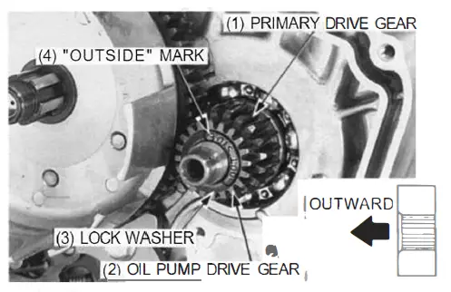
NOTE
Note the direction of the primary drive gear.
Install the clutch assembly (page 9-7).
Install the lock washer with its “OUTSIDE” mark facing out
RIGHT CRANKCASE COVER INSTALLATION
- Clean off any gasket material.
- Install the dowel pins and new gasket.
NOTE
Be careful not to damage the gasket mating surface.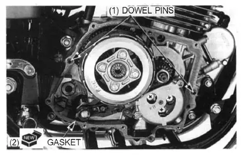
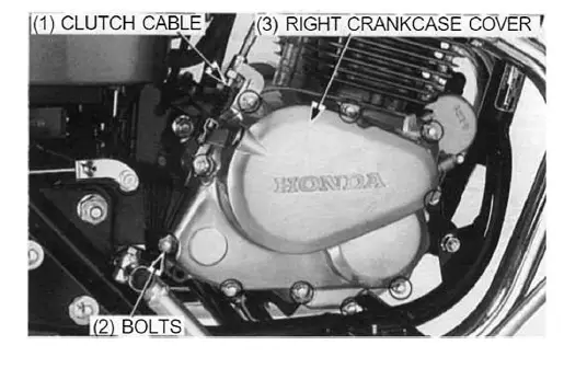
- Install the right crankcase cover and connect the clutch cable to the clutch arm.
- Set the clutch cable guide and tighten the right crankcase cover bolts.

- Install the right footpeg bracket and tighten the bolts.
- Adjust the clutch (page 3-18).
- Fill the crankcase with the recommended engine oil (page 3-9).
- Start the engine and check the clutch for smooth operation. Be sure there are no oil leaks.