BATTERY BACKUP POWER BBP-AR-33-EBP Battery Cabinet
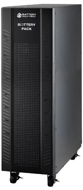
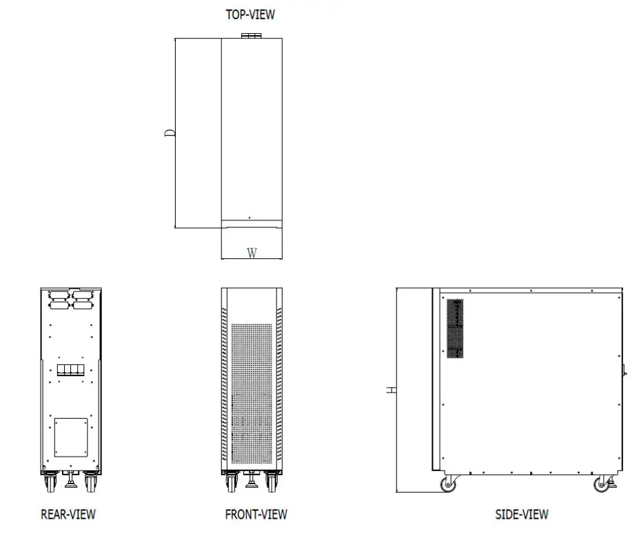
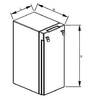
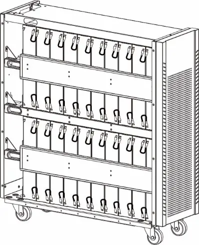
Cabinet Overlook
- Dimension (D x W x H): 780 mm x 250 mm x 840 mm
- Net weight for empty cabinet: 255kg
Preparation
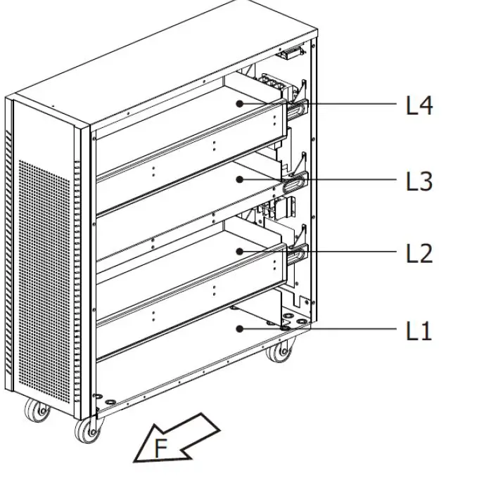
Mechanical Overview
- Battery cabinet The “F” marks the front side of the battery cabinet.
- Battery shelf The cabinet includes four trays, from L1 (bottom) to L4 (top).
Battery Requirement
- Lead-Acid cell type and quantity : 12V 9.4Ah x 80 pieces
- Maximum size for lead-acid battery (L x W x H ) :65.8x 98.6x 152 mm.
Cable Specification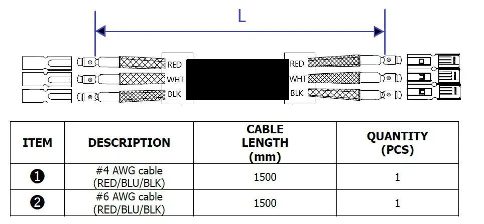
Note: PE-Wiring 6 AWG, Nut Torque: 105.9 lbf-in.
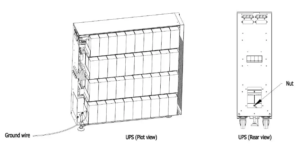
GND Connection Diagram
Please refer the below assembly step before operating.
- Remove the back cover on the rear panel.
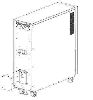
- Take off the knockouts.
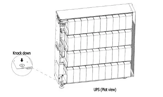
- Connect the ground wire then use nut to fix.

Caution:
- UPS and Remote Battery Supply Cabinet employed battery case with HB flame class: “Not for use in a computer room as define in the standard for the Protection
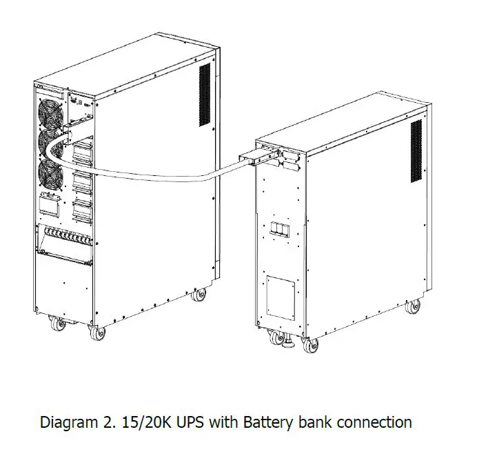
of Electronic Computer/Data Processing Equipment ANSI/NFPA 75”. - Battery replacement and remote battery supply cabinet installation shall be handled by SERVICE PERSONNEL only. Remote battery supply cabinet installation with UPS.
- Disconnection of all AC source and the DC source is required to de-energize this unit before servicing.
Battery Wiring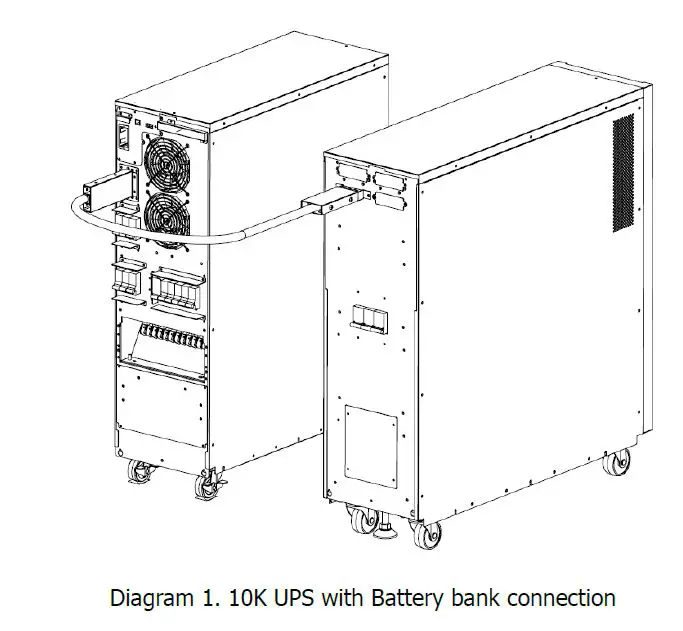
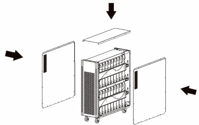
Installation
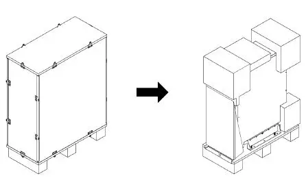
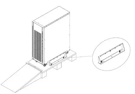
- Remove the carton and foam.
- Remove fixing plates on the two sides of the UPS by removing all screws as shown below.
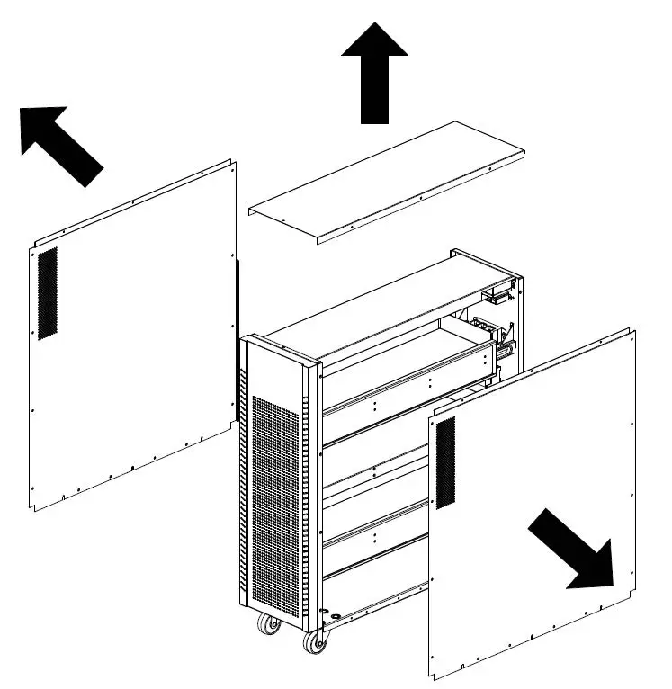
- Take out top and side panels by removing all screws as shown below.
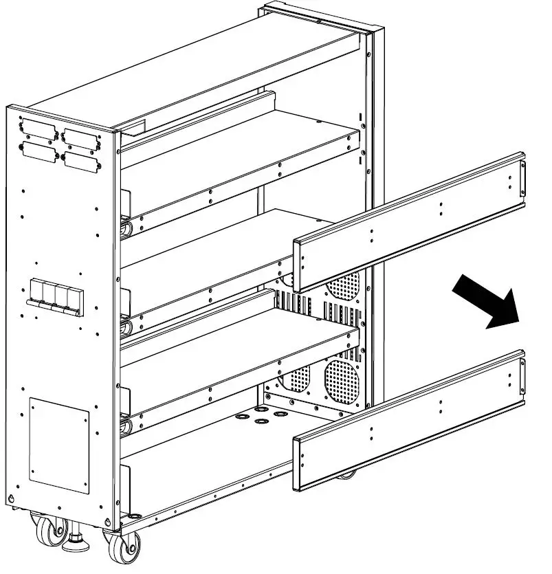
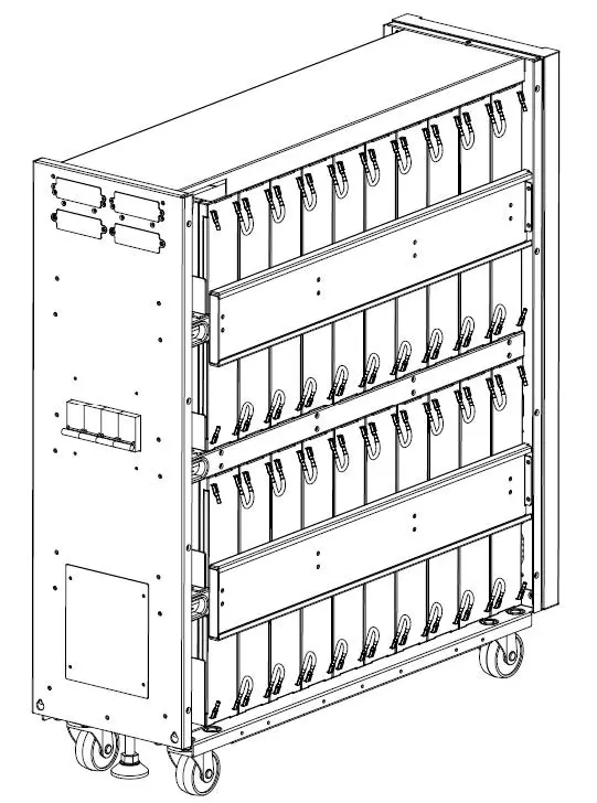
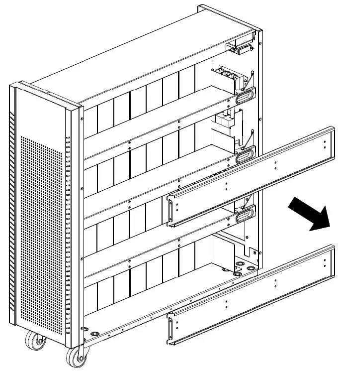
- Remove two (for 20K) and two (for 15K) battery fixing bars on the left side of the UPS.
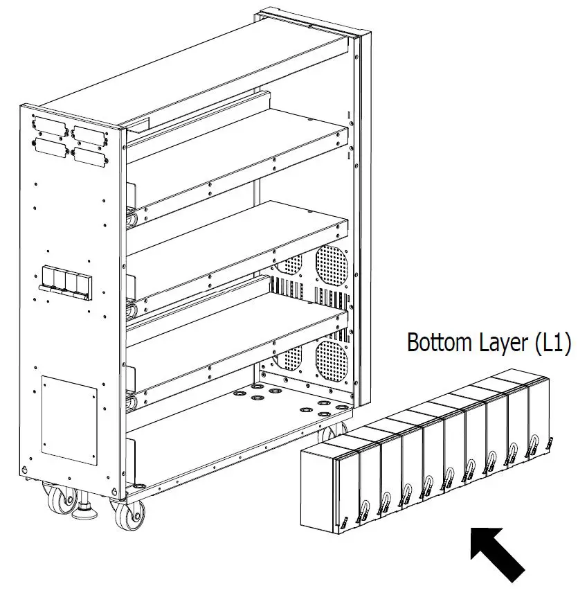
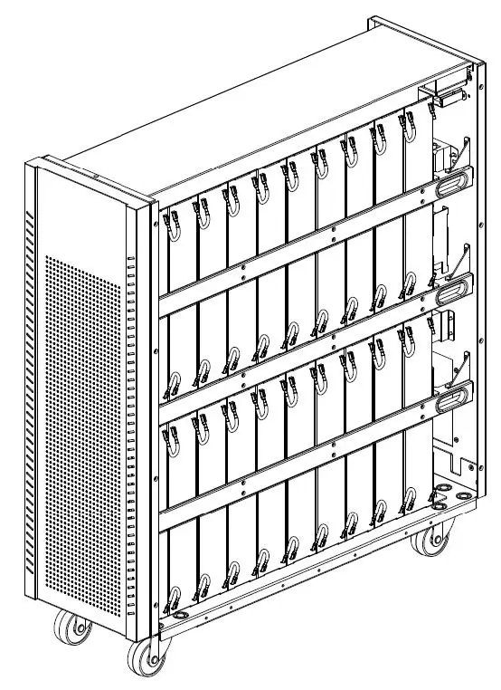
- Please install 10 battery packs as shown below to the bottom layer (L1). Be sure to keep the terminal sides of all batteries up.
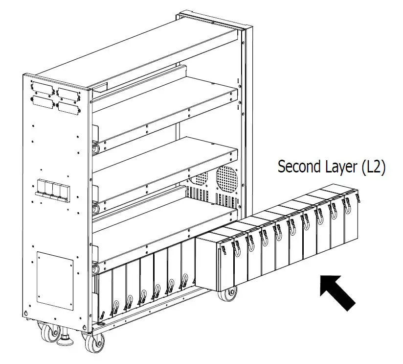
- Install another 10 battery packs as shown below to the third layer (L2). Be sure to keep the terminal sides of all batteries up.
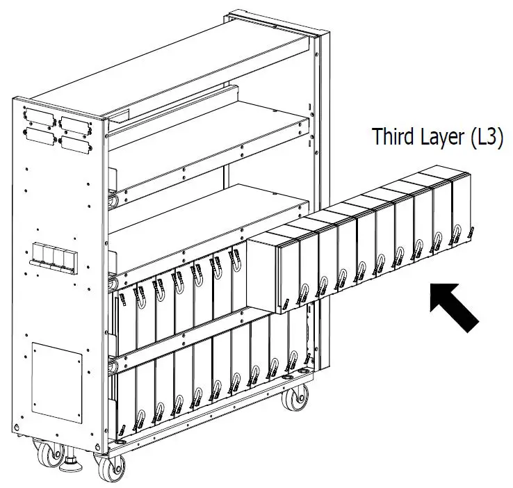
- Install another 10 battery packs as shown below to the second layer (L3). Be sure to keep the terminal sides of all batteries up.
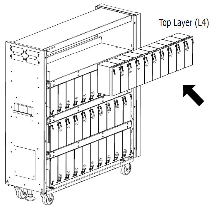
- Install another 10 battery packs as shown below to the top layer (L4). Be sure to keep the terminal sides of all batteries up.
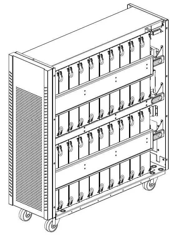
- Put two (for 20K) and two (for 15K) fixing battery bars back to the original place.
- Prepare to install the battery on the right side and first remove two (for 20K) and two (for 15K) battery fixing bars.
- Battery installation is from L1 to L4 according to the step5 to step8.
- Put two (for 20K) and two (for 15K) fixing battery bars back to the original place
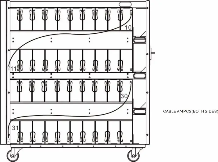
- Use one cable A to connect #10 and #11 batteries (for 15K and 20K). Use one more cable A to connect #30 and #31 batteries as shown below (only for 20K).

- On the left side of the UPS, use 36 pieces (for 20K) and 17 pieces (for 15K) of cable B*72 PCS (for 20K) and cable B*34 PCS (for 15K) to connect two terminals on all batteries as shown below.
- Use one cable A to connect #10 and #11 batteries (for 15K and 20K). Use one more cable A to connect #30 and #31 batteries as shown below (only for 20K).
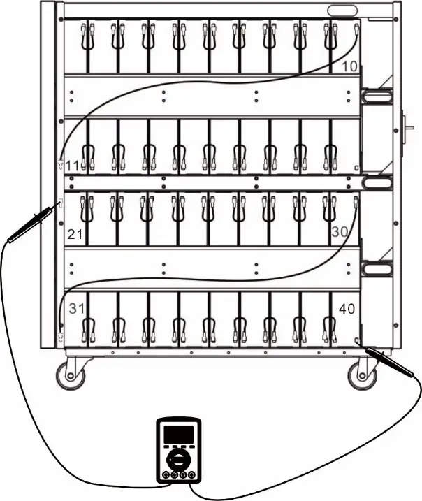
- On the right side of the UPS, use one meter to measure the positive pole of #40 battery and the negative pole of#21 battery. (DC voltage should be within 120V~130V)
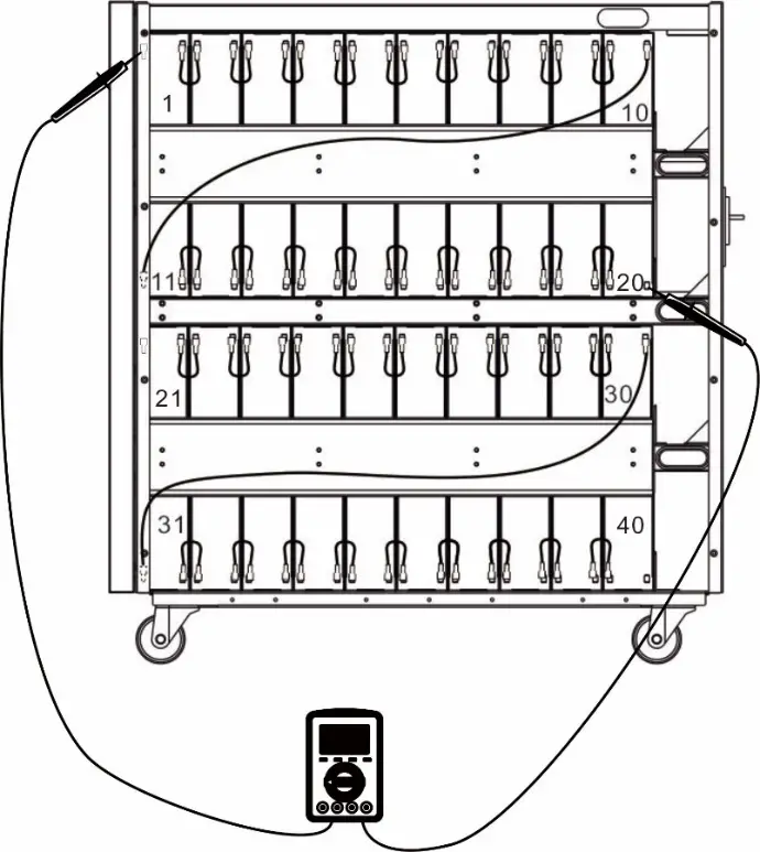
- Measure the positive pole of #20 battery and the negative pole of #1 battery. (DC voltage should be within 120V~130V).
- On the right side of the UPS, use one meter to measure the positive pole of #40 battery and the negative pole of#21 battery. (DC voltage should be within 120V~130V)
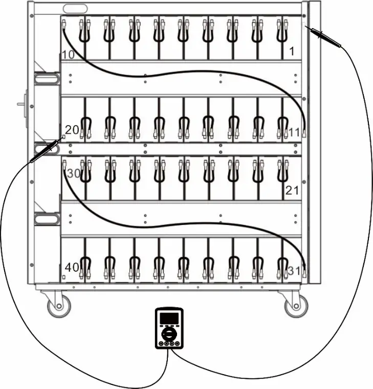
- On the left side of the UPS, use one meter to measure the positive pole of #1 battery and the negative pole of#20 battery. (DC voltage should be within 120V~130V)

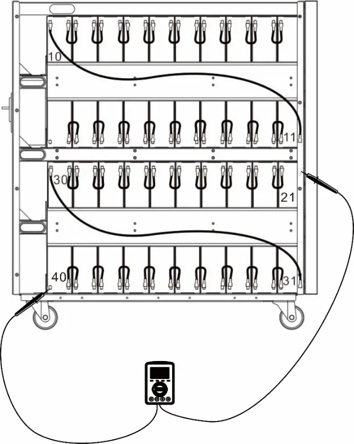
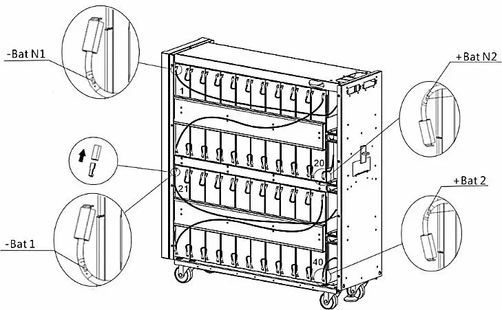
- On the left side of the UPS, there are 6 cables (for 20K) and 4 cable (for 15K) with label marks. Please follow below chart to connect each cable.
- On the right side of the UPS, there are 6 cables (for 20K) and 4 cable (for 15K) with label marks. Please follow below chart to connect each cable.
- Put top and side panels back to original place as shown below.