

Quickstart
This is a
secure
HVAC-Thermostat
for
.
To run this device please connect it to your mains power supply.
Important safety information
Please read this manual carefully. Failure to follow the recommendations in this manual may be dangerous or may violate the law.
The manufacturer, importer, distributor and seller shall not be liable for any loss or damage resulting from failure to comply with the instructions in this manual or any other material.
Use this equipment only for its intended purpose. Follow the disposal instructions.
Do not dispose of electronic equipment or batteries in a fire or near open heat sources.
What is Z-Wave?
Z-Wave is the international wireless protocol for communication in the Smart Home. This
device is suited for use in the region mentioned in the Quickstart section.

Z-Wave ensures a reliable communication by reconfirming every message (two-way
communication) and every mains powered node can act as a repeater for other nodes
(meshed network) in case the receiver is not in direct wireless range of the
transmitter.
This device and every other certified Z-Wave device can be used together with any other
certified Z-Wave device regardless of brand and origin as long as both are suited for the
same frequency range.
If a device supports secure communication it will communicate with other devices
secure as long as this device provides the same or a higher level of security.
Otherwise it will automatically turn into a lower level of security to maintain
backward compatibility.
For more information about Z-Wave technology, devices, white papers etc. please refer
to www.z-wave.info.
Product Description
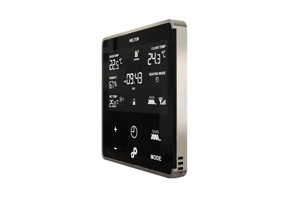
The HE-HT01 is HELTUNs advanced programmable thermostat for heating systems that is impossibly thin on the wall while being packed full of features. It delivers highly accurate comfort control using proprietary technology and four built-in sensors. Even though it stands out only 9mm from the wall, it provides all the information you need at-a-glance without having to touch the display. You can monitor and control the HE-HT01 from anywhere in the world using a Z-Wave hub and your smartphone.* And because it uses the Z-Wave 700 Platform, SmartStart, and S2 Security, the HE-HT01 can be placed up to 100 meters away from the hub and is a snap to install. Best of all, real-time and cumulative energy consumption meters help you save money on energy costs while staying comfortable all year long.The HELTUN HE-HT01 is part of an entire line of smart, connected products designed to provide the best technology has to offer without compromising stylish living. (*hub and smartphone not included)
Prepare for Installation / Reset
Please read the user manual before installing the product.
In order to include (add) a Z-Wave device to a network it must be in factory default
state. Please make sure to reset the device into factory default. You can do this by
performing an Exclusion operation as described below in the manual. Every Z-Wave
controller is able to perform this operation however it is recommended to use the primary
controller of the previous network to make sure the very device is excluded properly
from this network.
Safety Warning for Mains Powered Devices
ATTENTION: only authorized technicians under consideration of the country-specific
installation guidelines/norms may do works with mains power. Prior to the assembly of
the product, the voltage network has to be switched off and ensured against re-switching.
Inclusion/Exclusion
On factory default the device does not belong to any Z-Wave network. The device needs
to be added to an existing wireless network to communicate with the devices of this network.
This process is called Inclusion.
Devices can also be removed from a network. This process is called Exclusion.
Both processes are initiated by the primary controller of the Z-Wave network. This
controller is turned into exclusion respective inclusion mode. Inclusion and Exclusion is
then performed doing a special manual action right on the device.
Quick trouble shooting
Here are a few hints for network installation if things dont work as expected.
- Make sure a device is in factory reset state before including. In doubt exclude before include.
- If inclusion still fails, check if both devices use the same frequency.
- Remove all dead devices from associations. Otherwise you will see severe delays.
- Never use sleeping battery devices without a central controller.
- Dont poll FLIRS devices.
- Make sure to have enough mains powered device to benefit from the meshing
Association – one device controls an other device
Z-Wave devices control other Z-Wave devices. The relationship between one device
controlling another device is called association. In order to control a different
device, the controlling device needs to maintain a list of devices that will receive
controlling commands. These lists are called association groups and they are always
related to certain events (e.g. button pressed, sensor triggers, …). In case
the event happens all devices stored in the respective association group will
receive the same wireless command wireless command, typically a ‘Basic Set’ Command.
Association Groups:
Group NumberMaximum NodesDescription
| 1 | 1 | This is the Lifeline Group 1 which sends status (lifeline) reports to the primary controller. |
| 2 | 1 | Group 2Basic Set On/Off: is assigned to the HE-HT01 operating state. It sends a Basic Set command with value 0 (Off) when it goes to IDLE state and sends 255 (ON) when it goes into HEATING state. |
Configuration Parameters
Z-Wave products are supposed to work out of the box after inclusion, however
certain configuration can adapt the function better to user needs or unlock further
enhanced features.
IMPORTANT: Controllers may only allow configuring
signed values. In order to set values in the range 128 … 255 the value sent in
the application shall be the desired value minus 256. For example: To set a
parameter to 200 it may be needed to set a value of 200 minus 256 = minus 56.
In case of a two byte value the same logic applies: Values greater than 32768 may
needed to be given as negative values too.
Parameter 1: NTC RESISTANCE
Floor Sensor Resistance (k)
Size: 1 Byte, Default Value: 10
SettingDescription
| 1 – 100 | Floor Sensor Resistance in kiloOhms (k) |
Parameter 10: TIME FORMAT
Time format
Size: 1 Byte, Default Value: 1
SettingDescription
| 0 | 24 hour format |
| 1 – 0 | 12 hour (AM/PM) format |
Parameter 11: WEEKDAY
Week day. This parameter allows manually adjustment of the day of the week in case if the thermostat is not connected to any Z-Wave gateway or Parameter 09 (auto-correction) is selected as 0.
Size: 1 Byte, Default Value: 1
SettingDescription
| 1 – 0 | Monday |
| 2 – 0 | Tuesday |
| 3 – 0 | Wednesday |
| 4 – 0 | Thursday |
| 5 – 0 | Friday |
| 6 – 0 | Saturday |
| 7 – 0 | Sunday |
Parameter 12: HOUR
Time hour
Size: 1 Byte, Default Value: 0
SettingDescription
| 0 – 23 | This Parameter allows manual adjustment of Time in hours (24 hours). |
Parameter 13: MINUTE
Time minutes
Size: 1 Byte, Default Value: 0
SettingDescription
| 0 – 59 | This Parameter allows manual adjustment of the Time in minutes (60 minutes)) |
Parameter 14: AIR TEMP MIN
Air Temperature Minimum in C, value X 10, e.g. 22.5C=225The AIR TEMP MIN value cannot be higher than AIR TEMP MAX value 10
Size: 2 Byte, Default Value: 210
SettingDescription
| 40 – 360 | This Parameter is the room temperature low limitreading the internal temperature sensor. This only comes into effect if FA or PA are selected as the source sensor in Parameter 04. The factory default value is 21C (69F). Note: The AtL value cannot be higher than AtH value 1C. |
Parameter 15: AIR TEMP MAX
Air Temperature Maximum in C, x10The AIR TEMP MAX value cannot be lower than AIR TEMP MIN value +10
Size: 2 Byte, Default Value: 270
SettingDescription
| 50 – 370 | This Parameter is the room temperature high limitreading the internal temperature sensor. This only comes into effect if FA or PA are selected as the source sensor in Parameter 4. The factory default value is 27C (80F). Note: The AtH value cannot be lower than AtL value +1C. |
Parameter 16: FLOOR TEMP MIN
Floor Temperature Minimum in C, x10The FLOOR TEMP MIN value cannot be higher than FLOOR TEMP MAX value 10
Size: 2 Byte, Default Value: 180
SettingDescription
| 40 – 360 | This Parameter is the floor temperature low limitreading the external NTC temperature sensor. It only comes into effect if AF or PF are selected as the source sensor. The factory default value is 18C or 64F. Note: The FtL value cannot be higher than FtH value 1C. |
Parameter 17: FLOOR TEMP MAX
Floor Temperature Maximum in C, x10The FLOOR TEMP MAX value cannot be lower than FLOOR TEMP MIN value +10
Size: 2 Byte, Default Value: 320
SettingDescription
| 50 – 370 | This Parameter is the floor temperature high limitreading the external NTC temperature sensor. It only comes into effect if AF or PF are selected as the source sensor. The factory default value is 32C (89F). Note: The FtH value cannot be lower than FtL value +1C. |
Parameter 18: DEGREE MODE
Degree mode (C/F)Floor and air temperature, as well as Set Point and all Parameters will be indicated in the chosen mode. Factory default value is degrees Celsius (0).
Size: 1 Byte, Default Value: 0
SettingDescription
| 0 | Celsius |
| 1 – 0 | Fahrenheit |
Parameter 19: AIR TEMP CORRECTION
Air Temperature Calibration in C, x10.This Parameter defines the offset value for room air temperature. If the internal air temperature sensor is not correctly calibrated, then manual calibration can be made by adjusting the values up to 9.5C or 17F (this value will be added or subtracted from the internal air temperature sensor reading).
Size: 1 Byte, Default Value: 0
SettingDescription
| -95 – 95 | This value will be added or subtracted from the internal air temperature sensor reading. |
Parameter 2: S1 INPUT MODE
S1 input mode
Size: 1 Byte, Default Value: 0
SettingDescription
| 0 | No action will be taken (the input state is ignored by the Thermostat logic). |
| 1 – 0 | Thermostat will be switched to the operating mode selected in Parameter 3 if the output was short-circuited. The Heating Thermostat will go back to previous mode as soon as the input is open. |
| 2 – 0 | Thermostat will be switched to the operating mode selected in Parameter 3 if the output was short-circuited, but it will not undertake any action if the input is open again. |
Parameter 20: FLOOR TEMP CORRECTION
Floor Temperature Calibration in C, x10.This Parameter defines the offset value for floor temperature. If the external floor temperature sensor is not calibrated properly, then manual calibration can be made by adjusting the values up to 9.5C or 17F (this value will be added or subtracted from the floor temperature sensor reading).
Size: 1 Byte, Default Value: 0
SettingDescription
| -95 – 95 | This value will be added or subtracted from the floor temperature sensor reading. |
Parameter 21: TEMP HYSTERESYS
Temperature Hysteresis in C, x10.The HE-HT01 will stabilize the temperature with selected hysteresis. For example, if the SET POINT is set for 25C and HYSTERESIS is set for 0.5C the HE-HT01 will change the state to IDLE if the temperature reaches 25.0C, but it will change the state to HEATING if the temperature becomes lower than 24.5C. The hysteresis can be changed from 0.2C to 10.0C range in Celsius mode, and from 0.3F to 18.0F in Fahrenheit mode. The factory default value is 0.5C (0.9F).
Size: 1 Byte, Default Value: 5
SettingDescription
| 2 – 100 | Hysteresis value for temperature control. |
Parameter 22: AUTO BRIGHTNESS
Display auto-brightness control.
Size: 1 Byte, Default Value: 1
SettingDescription
| 0 | Manual Control: display inactive state brightness will be set to the level defined by Parameter 23. |
| 1 – 0 | Automatic Brightness Control. |
Parameter 23: MANUAL BRIGHTNESS
Display manual brightness level.The Display Brightness Level Parameter will take effect when Parameter 22 is set to Manual Control (value = 0). Note: The environment illumination is displayed in the TIME position and also can be checked at any time via a Z-Wave gateway.
Size: 1 Byte, Default Value: 10
SettingDescription
| 1 – 15 | The LCD brightness may be adjusted from 1 (lowest brightness) to 15 (highest brightest). |
Parameter 24: TOUCH THRESHOLD
Touch buttons sensitivity.5 = Highly sensitive. 50 = Lowest sensitivity.Note: Setting the sensitivity too high can lead to false touch detection. We recommend not changing this Parameter unless there is a need to do so.
Size: 1 Byte, Default Value: 15
SettingDescription
| 5 – 50 | Threshold to be adjusted from level 5 (very sensitive) to 50 (minimal sensitivity). |
Parameter 25: RESERVED
Parameter reserved by the manufacturer. Setting this parameter will have no impact on DUT functionality.
Size: 1 Byte, Default Value: 0
SettingDescription
| 0 | Parameter reserved by the manufacturer. Setting this parameter will have no impact on DUT functionality. |
| 1 – 0 | Parameter reserved by the manufacturer. Setting this parameter will have no impact on DUT functionality. |
Parameter 26: RESERVED
Parameter reserved by the manufacturer. Setting this parameter will have no impact on DUT functionality.
Size: 1 Byte, Default Value: 0
SettingDescription
| 0 | Parameter reserved by the manufacturer. Setting this parameter will have no impact on DUT functionality. |
| 1 – 0 | Parameter reserved by the manufacturer. Setting this parameter will have no impact on DUT functionality. |
Parameter 27: RESERVED
Parameter reserved by the manufacturer. Setting this parameter will have no impact on DUT functionality.
Size: 1 Byte, Default Value: 0
SettingDescription
| 0 | Parameter reserved by the manufacturer. Setting this parameter will have no impact on DUT functionality. |
| 1 – 0 | Parameter reserved by the manufacturer. Setting this parameter will have no impact on DUT functionality. |
Parameter 28: RESERVED
Parameter reserved by the manufacturer. Setting this parameter will have no impact on DUT functionality.
Size: 1 Byte, Default Value: 0
SettingDescription
| 0 | Parameter reserved by the manufacturer. Setting this parameter will have no impact on DUT functionality. |
| 1 – 0 | Parameter reserved by the manufacturer. Setting this parameter will have no impact on DUT functionality. |
Parameter 29: RESERVED
Parameter reserved by the manufacturer. Setting this parameter will have no impact on DUT functionality.
Size: 1 Byte, Default Value: 0
SettingDescription
| 0 | Parameter reserved by the manufacturer. Setting this parameter will have no impact on DUT functionality. |
| 1 – 0 | Parameter reserved by the manufacturer. Setting this parameter will have no impact on DUT functionality. |
Parameter 3: S1 INPUT ACTION
Mode number for S1 input action
Size: 1 Byte, Default Value: 6
SettingDescription
| 1 – 0 | COM mode |
| 2 – 0 | TIME mode |
| 3 – 0 | DRY mode |
| 4 – 0 | ECO mode |
| 5 – 0 | VAC mode |
| 6 – 0 | MAN mode with IDLE (Off) state |
| 7 – 0 | MAN mode with HEATING (On) state |
Parameter 30: BASIC SET MODE
Mode to switch to on Basic Set Action command receive.This Parameter defines which Operating Mode the HE-HT01 reverts to if the Basic Set command is received. If the Basic Set command value is 0 (OFF state) the HE-HT01 will go to Manual (MAN) mode and switch off the heating element (IDLE mode). If the Basic Set command is 1 or higher (ON state) the HE-HT01 will change the Mode to the corresponding selected Parameter value.
Size: 1 Byte, Default Value: 1
SettingDescription
| 1 – 0 | COM mode |
| 2 – 0 | TIME mode |
| 3 – 0 | DRY mode |
| 4 – 0 | ECO mode |
| 5 – 0 | VAC mode |
| 6 – 0 | MAN Mode with HEATING state |
Parameter 31: RESERVED
Parameter reserved by the manufacturer. Setting this parameter will have no impact on DUT functionality.
Size: 1 Byte, Default Value: 0
SettingDescription
| 0 | Parameter reserved by the manufacturer. Setting this parameter will have no impact on DUT functionality. |
| 1 – 0 | Parameter reserved by the manufacturer. Setting this parameter will have no impact on DUT functionality. |
Parameter 32: RESERVED
Parameter reserved by the manufacturer. Setting this parameter will have no impact on DUT functionality.
Size: 1 Byte, Default Value: 0
SettingDescription
| 0 | Parameter reserved by the manufacturer. Setting this parameter will have no impact on DUT functionality. |
| 1 – 0 | Parameter reserved by the manufacturer. Setting this parameter will have no impact on DUT functionality. |
Parameter 33: RESERVED
Parameter reserved by the manufacturer. Setting this parameter will have no impact on DUT functionality.
Size: 1 Byte, Default Value: 0
SettingDescription
| 0 | Parameter reserved by the manufacturer. Setting this parameter will have no impact on DUT functionality. |
| 1 – 0 | Parameter reserved by the manufacturer. Setting this parameter will have no impact on DUT functionality. |
Parameter 34: RESERVED
Parameter reserved by the manufacturer. Setting this parameter will have no impact on DUT functionality.
Size: 1 Byte, Default Value: 0
SettingDescription
| 0 | Parameter reserved by the manufacturer. Setting this parameter will have no impact on DUT functionality. |
| 1 – 0 | Parameter reserved by the manufacturer. Setting this parameter will have no impact on DUT functionality. |
Parameter 35: RESERVED
Parameter reserved by the manufacturer. Setting this parameter will have no impact on DUT functionality.
Size: 1 Byte, Default Value: 0
SettingDescription
| 0 | Parameter reserved by the manufacturer. Setting this parameter will have no impact on DUT functionality. |
| 1 – 0 | Parameter reserved by the manufacturer. Setting this parameter will have no impact on DUT functionality. |
Parameter 36: RESERVED
Parameter reserved by the manufacturer. Setting this parameter will have no impact on DUT functionality.
Size: 1 Byte, Default Value: 0
SettingDescription
| 0 | Parameter reserved by the manufacturer. Setting this parameter will have no impact on DUT functionality. |
| 1 – 0 | Parameter reserved by the manufacturer. Setting this parameter will have no impact on DUT functionality. |
Parameter 37: RESERVED
Parameter reserved by the manufacturer. Setting this parameter will have no impact on DUT functionality.
Size: 1 Byte, Default Value: 0
SettingDescription
| 0 | Parameter reserved by the manufacturer. Setting this parameter will have no impact on DUT functionality. |
| 1 – 0 | Parameter reserved by the manufacturer. Setting this parameter will have no impact on DUT functionality. |
Parameter 38: RESERVED
Parameter reserved by the manufacturer. Setting this parameter will have no impact on DUT functionality.
Size: 1 Byte, Default Value: 0
SettingDescription
| 0 | Parameter reserved by the manufacturer. Setting this parameter will have no impact on DUT functionality. |
| 1 – 0 | Parameter reserved by the manufacturer. Setting this parameter will have no impact on DUT functionality. |
Parameter 39: RESERVED
Parameter reserved by the manufacturer. Setting this parameter will have no impact on DUT functionality.
Size: 1 Byte, Default Value: 0
SettingDescription
| 0 | Parameter reserved by the manufacturer. Setting this parameter will have no impact on DUT functionality. |
| 1 – 0 | Parameter reserved by the manufacturer. Setting this parameter will have no impact on DUT functionality. |
Parameter 4: SOURCE TYPE
Source Sensor: 1=A, 2=AF, 3=F, 4=FA, 5=P, 6=PA, 7=PF
Size: 1 Byte, Default Value: 6
SettingDescription
| 1 – 0 | AAir sensor.Regulation (heating control) is based on the SET POINT applied to the internal room air temperature sensor. |
| 2 – 0 | AFAir sensor + Floor sensor. Regulation is based on SET POINT applied to the internal room temperature sensor but also controlled by the floor temperature sensor ensuring that the floor temperature remains within the set limits. The lower floor temperature limit is specified in Parameter 16 (FtL) and the high temperature limit in parameter 17 (FtH). |
| 3 – 0 | FFloor sensor.Regulation is based on the SET POINT applied to the external floor temperature sensor. |
| 4 – 0 | FAFloor sensor + Air sensor.Regulation is based on SET POINT applied to the external floor sensor but is also controlled by the internal air temperature sensor ensuring that the room temperature remains within the set limits. The lower air temperature limit is specified in Parameter 14 (AtL) and the higher temperature limit in Parameter 15 (AtH). |
| 5 – 0 | PPower regulator.Regulation is based on the time settings for heating which will be ON during the time in Parameter 05 (POn) and then OFF during the time in Parameter 06 (POf). This cycle will be repeated constantly. |
| 6 – 0 | PAPower regulator + Air sensor.Regulation is based on the time set by Parameters 05 and 06 but also controlled by the internal air temperature sensor ensuring that the room temperature remains within the set limits. The air temperature limits are specified in Parameters 14 and 15. |
| 7 – 0 | PFPower regulator + Floor sensor.Regulation is based on the time set by Parameters 05 and 06 but also controlled by the floor temperature sensor ensuring that the floor temperature remains within set limits. The floor temperature limits are specified in Parameters 16 and 17. |
Parameter 40: RESERVED
Parameter reserved by the manufacturer. Setting this parameter will have no impact on DUT functionality.
Size: 1 Byte, Default Value: 0
SettingDescription
| 0 | Parameter reserved by the manufacturer. Setting this parameter will have no impact on DUT functionality. |
| 1 – 0 | Parameter reserved by the manufacturer. Setting this parameter will have no impact on DUT functionality. |
Parameter 41: SENSORS REPORT TIME
Sensors consecutive reporting interval, minutes.When the device is connected to the Z-Wave gateway (controller), it periodically sends to the gateway reports from its room & floor temperature, humidity and light sensors even if there are not changes in the values. This Parameter defines the interval between consecutive reports. The value can be adjusted from 1 min to 120 min.Note: If the sensor readings change, the device will send the report to the gateway regardless of this parameter value. In order not to increase traffic on your network, it is not recommended to reduce the value of this parameter. We recommend to reduce the value of this parameter only in case of poor connection, when reports from the device does not always reach the gateway.
Size: 1 Byte, Default Value: 10
SettingDescription
| 1 – 120 | The value can be adjusted from 1 to 120 minutes |
Parameter 42: CONSUMPTION REPORT TIME
Consumption meter consecutive reporting interval, minutes.This Parameter defines the interval between consecutive reports of real time and cumulative energy consumption data to the gateway. The value can be adjusted from 1 min to 120 min. The factory default value is 10 min. Note: If the sensor readings change, the device will send the report to the gateway regardless of this parameter value. In order not to increase traffic on your network, it is not recommended to reduce the value of this parameter.
Size: 1 Byte, Default Value: 10
SettingDescription
| 1 – 120 | The value can be adjusted from 1 to 120 minutes. |
Parameter 43: TEMPERATURE THRESHOLD
Temperature difference to send to controller, value x10.This parameter determines the change in temperature level (in C) resulting in temperature sensors report being sent to the gateway. The value of this parameter should be x10, e.g. for 0.4C use value 40. From 0.5C to 10C can be selected. Use the value 0 if there is a need to stop sending the reports. The factory default value is 0.5C (5).
Size: 1 Byte, Default Value: 5
SettingDescription
| 0 | Stop sending the reports |
| 5 – 100 | Temperature level (in C) |
Parameter 44: HUMIDITY THRESHOLD
Humidity difference to send to controller, %.This parameter determines the change in humidity level in % resulting in humidity sensors report being sent to the gateway. From 2% to 25% can be selected. Use the value 0 if there is a need to stop sending the reports. The factory default value is 2.
Size: 1 Byte, Default Value: 2
SettingDescription
| 0 | Stop sending the reports |
| 2 – 25 | Humidity level in % |
Parameter 45: LIGHT THRESHOLD
Light sensor values difference to send to controller, %.This parameter determines the change in temperature level resulting in temperature sensors report being sent to the gateway. From 10% to 99% can be selected. Use the value 0 if there is a need to stop sending the reports. The factory default value is 50.
Size: 1 Byte, Default Value: 50
SettingDescription
| 0 | Stop sending the reports |
| 10 – 99 | Temperature level change in % |
Parameter 46: MORNING START TIME
Morning start time. Format: HHMM. e.g.08:00 should be sent as 0800
Size: 2 Byte, Default Value: 600
SettingDescription
| 0 – 2359 | Morning start time. Format: HHMM (from 00:00 to 23:59) |
Parameter 47: DAY START TIME
Day start time. Format: HHMM.
Size: 2 Byte, Default Value: 900
SettingDescription
| 0 – 2359 | Day start time. Format: HHMM (from 00:00 to 23:59) |
Parameter 48: EVENING START TIME
Evening start time. Format: HHMM.
Size: 2 Byte, Default Value: 1800
SettingDescription
| 0 – 2359 | Evening start time. Format: HHMM (from 00:00 to 23:59) |
Parameter 49: NIGHT START TIME
Night start time. Format: HHMM.
Size: 2 Byte, Default Value: 2300
SettingDescription
| 0 – 2359 | Night start time. Format: HHMM (from 00:00 to 23:59) |
Parameter 5: POWER REGULATION ON TIME
Power Regulation ON time, min
Size: 2 Byte, Default Value: 30
SettingDescription
| 10 – 240 | This Parameter defines floor HEATING time in minutes when Power Regulator (P, PA or PF) is selected as the source sensor in Parameter 04. Time values can be changed in the range: 10 to 240 minutes. |
Parameter 50: MONDAY MORNING TEMP
Monday Morning temperature, valueX10
Size: 2 Byte, Default Value: 240
SettingDescription
| 40 – 370 | Monday Morning temperature value |
Parameter 51: MONDAY DAYTIME TEMP
Monday Day temperature, valueX10
Size: 2 Byte, Default Value: 200
SettingDescription
| 40 – 370 | Monday Day temperature value |
Parameter 52: MONDAY EVENING TEMP
Monday Evening temperature, valueX10
Size: 2 Byte, Default Value: 230
SettingDescription
| 40 – 370 | Monday Evening temperature value |
Parameter 53: MONDAY NIGHT TEMP
Monday Night temperature, valueX10
Size: 2 Byte, Default Value: 180
SettingDescription
| 40 – 370 | Monday Night temperature value |
Parameter 54: TUESDAY MORNING TEMP
Tuesday Morning temperature, valueX10
Size: 2 Byte, Default Value: 240
SettingDescription
| 40 – 370 | Tuesday Morning temperature value |
Parameter 55: TUESDAY DAYTIME TEMP
Tuesday Day temperature, valueX10
Size: 2 Byte, Default Value: 200
SettingDescription
| 40 – 370 | Tuesday Day temperature value |
Parameter 56: TUESDAY EVENING TEMP
Tuesday Evening temperature, valueX10
Size: 2 Byte, Default Value: 230
SettingDescription
| 40 – 370 | Tuesday Evening temperature value |
Parameter 57: TUESDAY NIGHT TEMP
Tuesday Night temperature, valueX10
Size: 2 Byte, Default Value: 180
SettingDescription
| 40 – 370 | Tuesday Night temperature value |
Parameter 58: WEDNESDAY MORNING TEMP
Wednesday Morning temperature, valueX10
Size: 2 Byte, Default Value: 240
SettingDescription
| 40 – 370 | Wednesday Morning temperature value |
Parameter 59: WEDNESDAY DAYTIME TEMP
Wednesday Day temperature, valueX10
Size: 2 Byte, Default Value: 200
SettingDescription
| 40 – 370 | Wednesday Day temperature value |
Parameter 6: POWER REGULATION OFF TIME
Power Regulation OFF time, min
Size: 2 Byte, Default Value: 30
SettingDescription
| 10 – 240 | This Parameter defines floor IDLE time in minutes when Power Regulator (P, PA or PF) is selected as the source sensor in Parameter 04. Time can be changed in the range: 10 to 240 minutes. |
Parameter 60: WEDNESDAY EVENING TEMP
Wednesday Evening temperature, valueX10
Size: 2 Byte, Default Value: 230
SettingDescription
| 40 – 370 | Wednesday Evening temperature value |
Parameter 61: WEDNESDAY NIGHT TEMP
Wednesday Night temperature, valueX10
Size: 2 Byte, Default Value: 180
SettingDescription
| 40 – 370 | Wednesday Night temperature value |
Parameter 62: THURSDAY MORNING TEMP
Thursday Morning temperature, valueX10
Size: 2 Byte, Default Value: 240
SettingDescription
| 40 – 370 | Thursday Morning temperature value |
Parameter 63: THURSDAY DAYTIME TEMP
Thursday Day temperature, valueX10
Size: 2 Byte, Default Value: 200
SettingDescription
| 40 – 370 | Thursday Day temperature value |
Parameter 64: THURSDAY EVENING TEMP
Thursday Evening temperature, valueX10
Size: 2 Byte, Default Value: 230
SettingDescription
| 40 – 370 | Thursday Evening temperature value |
Parameter 65: THURSDAY NIGHT TEMP
Thursday Night temperature, valueX10
Size: 2 Byte, Default Value: 180
SettingDescription
| 40 – 370 | Thursday Night temperature value |
Parameter 66: FRIDAY MORNING TEMP
Friday Morning temperature, valueX10
Size: 2 Byte, Default Value: 240
SettingDescription
| 40 – 370 | Friday Morning temperature value |
Parameter 67: FRIDAY DAYTIME TEMP
Friday Day temperature, valueX10
Size: 2 Byte, Default Value: 200
SettingDescription
| 40 – 370 | Friday Day temperature value |
Parameter 68: FRIDAY EVENING TEMP
Friday Evening temperature, valueX10
Size: 2 Byte, Default Value: 230
SettingDescription
| 40 – 370 | Friday Evening temperature value |
Parameter 69: FRIDAY NIGHT TEMP
Friday Night temperature, valueX10
Size: 2 Byte, Default Value: 180
SettingDescription
| 40 – 370 | Friday Night temperature value |
Parameter 7: DRY TIME
Dry Time, min
Size: 1 Byte, Default Value: 30
SettingDescription
| 5 – 90 | This Parameter specifies how long in minutes the Heating Thermostat will be in HEATING mode when the DRY mode is selected. After this time the HE-HT01 will enter the mode specified in Parameter 8. The time range is 5 to 90 minutes. |
Parameter 70: SATURDAY MORNING TEMP
Saturday Morning temperature, valueX10
Size: 2 Byte, Default Value: 240
SettingDescription
| 40 – 370 | Saturday Morning temperature value |
Parameter 71: SATURDAY DAYTIME TEMP
Saturday Day temperature, valueX10
Size: 2 Byte, Default Value: 200
SettingDescription
| 40 – 370 | Saturday Day temperature value |
Parameter 72: SATURDAY EVENING TEMP
Saturday Evening temperature, valueX10
Size: 2 Byte, Default Value: 230
SettingDescription
| 40 – 370 | Saturday Evening temperature value |
Parameter 73: SATURDAY NIGHT TEMP
Saturday Night temperature, valueX10
Size: 2 Byte, Default Value: 180
SettingDescription
| 40 – 370 | Saturday Night temperature value |
Parameter 74: SUNDAY MORNING TEMP
Sunday Morning temperature, valueX10
Size: 2 Byte, Default Value: 240
SettingDescription
| 40 – 370 | Sunday Morning temperature value |
Parameter 75: SUNDAY DAYTIME TEMP
Sunday Day temperature, valueX10
Size: 2 Byte, Default Value: 200
SettingDescription
| 40 – 370 | Sunday Day temperature value |
Parameter 76: SUNDAY EVENING TEMP
Sunday Evening temperature, valueX10
Size: 2 Byte, Default Value: 230
SettingDescription
| 40 – 370 | Sunday Evening temperature value |
Parameter 77: SUNDAY NIGHT TEMP
Sunday Night temperature, valueX10
Size: 2 Byte, Default Value: 180
SettingDescription
| 40 – 370 | Sunday Night temperature value |
Parameter 8: DRY SWITCH MODE
Mode to switch after Dry mode operation completion
Size: 1 Byte, Default Value: 1
SettingDescription
| 1 – 0 | COM mode |
| 2 – 0 | TIME mode |
| 4 – 0 | ECO mode |
| 5 – 0 | VAC mode |
| 6 – 0 | MAN mode mode with IDLE state |
Parameter 9: TIME CORRECTION
Time correction by controller
Size: 1 Byte, Default Value: 1
SettingDescription
| 0 | Switch off auto-correction |
| 1 – 0 | If thermostat is connected to a Z-Wave gateway, the time and day will be periodically polled and corrected from the gateway |
Technical Data
| Hardware Platform | ZGM130 |
| Device Type | Thermostat – HVAC |
| Network Operation | Always On Slave |
| Firmware Version | HW: 12 FW: 2.01 |
| Z-Wave Version | 7.11.1 |
| Certification ID | ZC12-19120023 |
| Z-Wave Product Id | 0x0344.0x0004.0x0001 |
| Thermostat HVAC Systems Supported | |
| Thermostat Modes | |
| Thermostat Power Source | |
| Firmware Updatable | |
| Neutral Wire Required | ok |
| Switch Type | |
| Security V2 | S2_UNAUTHENTICATED ,S2_AUTHENTICATED |
| Frequency | XXfrequency |
| Maximum transmission power | XXantenna |
Supported Command Classes
- Application Status
- Association Grp Info V3
- Association V2
- Basic V2
- Clock
- Configuration V4
- Device Reset Locally
- Firmware Update Md V5
- Indicator V3
- Manufacturer Specific V2
- Meter V4
- Multi Channel Association V3
- Powerlevel
- Security
- Security 2
- Sensor Multilevel V11
- Supervision
- Thermostat Mode V3
- Thermostat Operating State
- Thermostat Setpoint V3
- Transport Service V2
- Version V3
- Zwaveplus Info V2
Explanation of Z-Wave specific terms
- Controller — is a Z-Wave device with capabilities to manage the network.
Controllers are typically Gateways,Remote Controls or battery operated wall controllers. - Slave — is a Z-Wave device without capabilities to manage the network.
Slaves can be sensors, actuators and even remote controls. - Primary Controller — is the central organizer of the network. It must be
a controller. There can be only one primary controller in a Z-Wave network. - Inclusion — is the process of adding new Z-Wave devices into a network.
- Exclusion — is the process of removing Z-Wave devices from the network.
- Association — is a control relationship between a controlling device and
a controlled device. - Wakeup Notification — is a special wireless message issued by a Z-Wave
device to announces that is able to communicate. - Node Information Frame — is a special wireless message issued by a
Z-Wave device to announce its capabilities and functions.


 Heatit Z-wave Thermostat Heae5430499 Manual")


