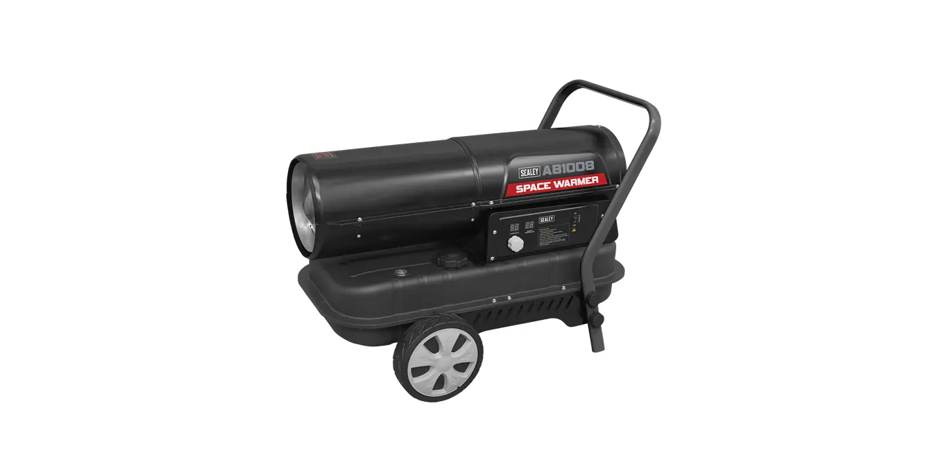
SEALEY AB1008.V4 Space Warmer Kerosene and Diesel Heaters With Wheels Instruction Manual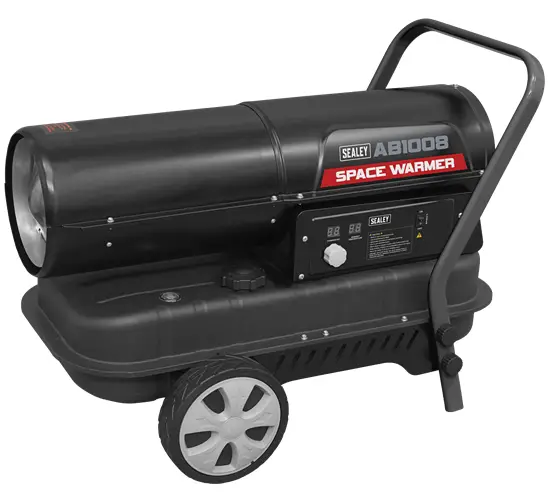
Introduction
Thank you for purchasing a Sealey product. Manufactured to a high standard, this product will, if used according to these instructions, and properly maintained, give you years of trouble free performance.
IMPORTANT: PLEASE READ THESE INSTRUCTIONS CAREFULLY. NOTE THE SAFE OPERATIONAL REQUIREMENTS, WARNINGS & CAUTIONS. USE THE PRODUCT CORRECTLY AND WITH CARE FOR THE PURPOSE FOR WHICH IT IS INTENDED. FAILURE TO DO SO MAY CAUSE DAMAGE AND/OR PERSONAL INJURY AND WILL INVALIDATE THE WARRANTY. KEEP THESE INSTRUCTIONS SAFE FOR FUTURE USE.
 Refer to instructions
![]() Warning! automatic start-up
Warning! automatic start-up
![]() Warning!! Hot surfaces
Warning!! Hot surfaces
![]() Warning
Warning
SAFETY
ELECTRICAL SAFETY
- WARNING! It is the responsibility of the owner and the operator to read, understand and comply with the following:
You must check all electrical products, before use, to ensure that they are safe. You must inspect power cables, plugs, sockets and any other connectors for wear or damage. You must ensure that the risk of electric shock is minimised by the installation of appropriate safety devices. A Residual Current Circuit Breaker (RCCB) should be incorporated in the main distribution board. You must also read and understand the following instructions concerning electrical safety. - Ensure that cables are always protected against short circuit and overload.
- Regularly inspect power supply cables and plugs for wear or damage and check all connections to ensure that none are loose.
- Ensure that the voltage marked on the appliance matches the power supply to be used and that the plug is fitted with the correct fuse – see fuse rating at right.
- DO NOT use worn or damaged cables, plugs or connectors. Have any faulty item repaired or replaced immediately by a competent electrician.
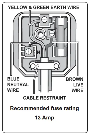
- It is recommended that this heater is wired directly to a fused isolator switch. If, however, a plug is fitted, the following applies:
- Fit a new plug according to the following instructions (UK only).
- Connect the GREEN/YELLOW earth wire to the earth terminal ‘E’.
- Connect the BROWN live wire to the live terminal ‘L’.
- Connect the BLUE neutral wire to the neutral terminal ‘N’.
- After wiring, check that there are no bare wires, that all wires have been correctly connected, that the cable restraint is tight.

GENERAL SAFETY Read instructions carefully. Read and follow all instructions. Place instructions in a safe place for future reference.
DO NOT allow anyone who has not read these instructions to assemble, light, adjust or operate the heater.
- If the information in this manual is not followed exactly, a fire or explosion may result causing property damage, personal injury or loss of life.
- Check that the heater is in sound condition and good working order. Servicing must be performed by qualified operatives only.
Take immediate action to repair or replace damaged parts. Use recommended parts only. Unapproved parts may be dangerous and will invalidate the warranty. - Only use clean kerosene or diesel (NOT BIO-DIESEL) to fuel your heater, in accordance with instructions contained in this manual.
- WARNING! Only use heater in well ventilated areas. Ensure continuous ventilation from outside of the building is provided to the heater operating area. Refer to 5.2 Installation Maximum OPening Size. Unvented portable heaters use air (oxygen) from the area in which it is used. Adequate combustion and ventilation air must be provided.
- WARNING! DO NOT store or use compressed air cylinders, petrol or other flammable liquids/gases in the vicinity of this or any other appliance.
- WARNING! fire, burning and inhalation hazard. Keep solid combustibles such as building materials, paper and cardboard away from the heater. Never use the heater in spaces which do or may contain volatile or airborne products such as petrol, solvents, paint thinner, dust particles or unknown chemicals.
- WARNING! Direct fired heaters may cause carbon monoxide (CO) poisoning when incorrectly used e.g. indoors without adequate air circulation, or if not working properly. CO poisoning may lead to death.
- DO NOT use the heater in closed rooms, living areas, basements or below ground level.
- DO NOT allow untrained persons to operate the heater and DO NOT operate the heater without the cover.
- DO NOT move or handle the heater when hot.
- DO NOT leave the heater unattended when in use. Switch the heater off and unplug from the mains before leaving work area.
- DO NOT fill the fuel tank whilst the heater is running or still hot.
- DO NOT overfill the fuel container. Wipe up any spilt fuel immediately.
- DO NOT obstruct the air inlet (rear) and air outlet (front) of the heater. DO NOT use duct work in front or at the rear of the heater.
- DO NOT look into the exhaust end of the heater.
- DO NOT allow children or animals near the heater when in use, or while hot.
- WARNING! not for recreational vehicle use.
- DANGER! the front outlet is very hot during operation. DO NOT touch danger of burning.
- WARNING! RISK OF ELECTRIC SHOCK. DO NOT expose the heater to water spray, rain, dripping water or wind.
- DO NOT touch the heater outlet or dome when first switched off as these are very hot and will take time to cool.
- Ensure that the heater is correctly turned off when not in use and store in a safe, dry area, out of reach of children.
- DO NOT unplug the heater to switch it off. Use the ON/OFF switch.
- WARNING! Improper maintenance can lead to poor combustion and soot production
- WARNING! IF YOU NEED ASSISTANCE OR HEATER INFORMATION SUCH AS AN INSTRUCTIONS MANUAL, LABELS, ETC. CONTACT THE MANUFACTURER.
NOTE:
This appliance is not intended for persons (including children) with reduced physical, sensory or mental capabilities, or lack of experience and knowledge, unless they have been given supervision or instruction concerning use of the appliance by a person responsible for their safety. Children should be supervised to ensure that they do not play with the appliance.
INTRODUCTION
35,000Btu/hr, 70,000Btu/hr Heat output Clean burning and proven pump system can operate with either kerosene or diesel. Stainless steel combustion chamber. Dual LED Display for ambient and thermostatically controlled desired temperature. Fitted with safety cut-outs and fuel gauge. Complies with rigorous standards.
SPECIFICATION
| Model no. | AB1008 | AB1258 | AB1758 |
| Airflow (cfm) | 441 | 529 | 647 |
| Electrical fuse rating | 13A | ||
| Electrical Plug type | 3-pin BS | ||
| Fuel | Kerosene/Diesel | ||
| Fuel tank | 34L | 50L | |
| Heated area | 28,250ft³(800m³) | 42,300ft³(1,200m³) | 49,500ft³(1,400m³) |
| Motor power | 230W | 340W | |
| Output | 100,000Btu/hr(30kW) | 135,000Btu/hr(40kW) | 170,000Btu/hr(50kW) |
| Running time per filling (max.) | 14hr | 11hr | |
| Supply | 230V~50Hz | ||
| Transport wheels | Yes | ||
ASSEMBLY
- To assemble the heater, proceed as follows (see Fig.1):
- Insert the wheel shaft E into the corresponding hole of the caster fixing plate J, insert the cotter I to the corresponding holes of the wheel shaft; put plain washer F to the two sides of shaft, slide the wheel D over the wheel shaft E, screw the nut G to fix the wheel on the shaft
- Install the wheel cover H.
- Use the clamping screw C and Plain washer ø6 B to install the Handle A into the corresponding hole of the caster fixing plate J.

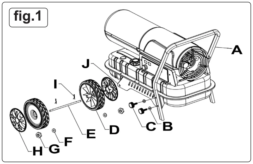
| No. | Description | Qty. |
| A | Handle | 1 |
| B | Plain washer Ø6mm | 4 |
| C | Clamping screw | 4 |
| D | Wheel | 2 |
| E | Wheel shaft | 1 |
| F | Plain washer Ø12mm | 2 |
| G | Nut M12 | 2 |
| H | Wheel cover | 2 |
| I | Cotter pin | 2 |
| J | Castor fixing plate | 2 |
INSTALLATION
- Position the heater on a flat, level, non-flammable, solid surface.
- Direct-fired heaters are intended for use in outdoor open areas or in indoor well ventilated areas. For indoor use, provide permanent ventilation openings of at least 25 cm²/kW, equally distributed between floor and high level, with a minimum of 250 cm².
Maximum Opening Size:
AB1008 – 800cm2
AB1258, AB1758 – 1250cm2
- Only install the heater in normal upright position.
- DO NOT place the heater near walls, corners or low ceilings.
- DO NOT place the heater below a socket outlet.
- DO NOT place the heater on moving vehicles or where it can tip over.
- Keep the heater away from flammable, combustible, explosive or corrosive materials.
- Keep the heater away from curtains or similar materials that could block the air inlet and outlet.
- Never block or restrict the air inlet and outlet for any reason.
- Keep the power cable away from heat sources, sharp edges, cutting and moving parts.
- DO NOT expose directly to the weather or to excessive humidity.
- DO NOT place the heater in the immediate surroundings of a bath, shower or swimming pool
Follow general and special fire safety regulations in force in all fields of applications. In any case ensure the following minimum safety clearances from materials or objects in the surroundings of the heater:
Side: 0.6 m
Air inlet side: 1 m
Top: 1.5 m
Hot air outlet side: 3 m
Floor: 0 m
Floors and ceilings must be made of fireproof materials in the place where the heater is operated.
- DO NOT connect direct-fired heaters to air ducts
OPERATING CONDITIONS
- KEROSENE AND DIESEL FUEL USAGE
These AB heaters are factory adjusted to give the most efficient burn on kerosene but will also burn diesel. Note that kerosene will tend to burn more cleanly than diesel. Care should be taken to provide at least the minimum amount of ventilation recommended when burning diesel. - STORAGE OF FUEL
Always store kerosene and diesel in a well ventilated area well away from general living space. Do not store in direct sunlight or near a source of heat or other source of ignition such as a torch or a portable generator. Do not use fuel that has been stored from one season to the next as it may have deteriorated and will not burn properly in the heater. Store the fuel in a suitable container which complies with requirements set out in local authority regulations. - WARNING! Air contaminants taken into the heater may affect the heat output, damage the unit and may cause health problems. Example: Bodyshop filler dust / paint overspray will damage the motor bearing, clog the filter and pump and contaminate the combustion chamber causing flame flutter and health hazards. Please note that any parts damaged by filler dust / paint overspray will not be covered
by warranty. Additionally, a cleaning charge will be made for any heaters damaged by filler dust.
OPERATION
(REF. FIG.1A)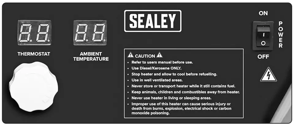
START UP
- gauge on top of the tank allows to check fuel level.
- Connect the power cord plug to a AC220-240V 50 Hz earthed electrical supply system. Earthing is mandatory.
- When complete “start-up” above, the left display window shows “–”, the right display window shows ambient temperature value.
- Push the power switch to “ON”(1) position.
- The default temperature setting is 20°C, shown on the left display window.
- If the ambient temperature is lower than default temperature, the electrodes start sparking, after 7 seconds, the heater starts.
- If the ambient temperature is higher than default temperature, turn thermostat control knob to desired temperature, the electrodes start sparking, after 7 seconds, the heater starts.
COLD START UP
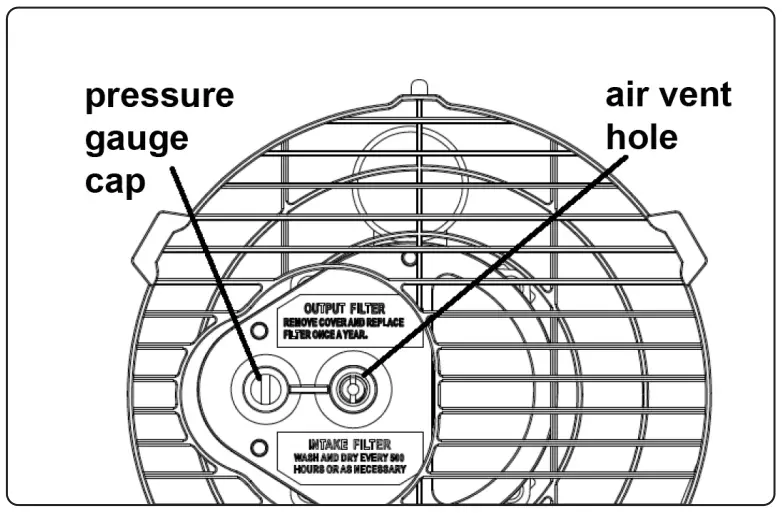
- At low temperature keep the air vent hole fig.4 closed by a finger during ignition to make start-up easier.
- ABNORMAL OPERATION: in case of malfunction (flame failure, reduced air flow, bad combustion, etc.) the heater stops and the indicator light starts FLASHING (THE LOCK-OUT MODE code will be showed on the display window).
MANUAL REST/RESTART
- If the heater is in lock-out mode, check and remove the cause of lock-out before restarting the heater.
- To reset, turn the ON/OFF switch to 0 and then again to I. In case of repeated malfunction, call technical service.
Turning the thermostat control knob will NOT reset the heater.
SHUT DOWN
- Move switch to “OFF” (O) position. Unplug the unit when not used for a long time.
- Never disconnect the heater from mains to stop it while in operation. Always allow the cooling sequence to be completed, otherwise the residual heat could damage internal components.
- DO NOT cover the heater.
- DO NOT block the air inlet and outlet.
- WARNING! The heater outlet is very hot during operation and after use. DO NOT TOUCH! Use personal protecting equipment if needed.
- WARNING! Children should be supervised to ensure that they do not play with the appliance.
Note: The appliance is not intended for use by persons (including children) with reduced physical, sensory or mental capabilities, or lack of experience and knowledge.
Unplug the heater before moving it. Never pull the cable to unplug or move the unit.
- DO NOT leave the heater unattended when in use.
- Never use the appliance with wet hands or when either the heater or the power cable is wet.
- WARNING! If the supply cable is damaged, it must be replaced by the manufacturer, by a service agent or a similar qualified person.
CLEANING & MAINTENANCE
- WARNING! Before starting any maintenance task, shut down, unplug and let the heater cool down for at least 15 minutes.
- DO NOT attempt any electrical repair yourself. If the heater needs service or repair, contact a qualified technician.
- DO NOT use a faulty unit unless a qualified technician has inspected and repaired it.
- When cleaning, make sure that water does not enter the unit.
- DO NOT open the enclosure to clean the inner parts. DO NOT spray water into the heater.
- Never use solvents, gasoline, toluene and similar aggressive chemicals to clean the heater.
- Regularly wipe the enclosure using a soft sponge or cloth. For very dirty parts, use a sponge wetted with lukewarm water and a mild detergent, then dry using a clean cloth.
- Keep air inlet and fan free from dust and dirt. To clean inner parts, gently blow compressed air through air inlet.
- Regularly inspect the power cable: if worn, cracked or damaged have it replaced by technical service.
- Before storing the heater, make sure it is perfectly cool and dry. Cover the unit with a plastic bag, put it in its packing box and store it in a dry, ventilated place.
LONG TERM STORAGE
If the heater is to be stored for a long period of time, drain the fuel through the fuel cap opening. Rinse and swirl a small amount of fuel within the tank and then empty it fully. When you come to use the heater again do not use old fuel which has been stored from the previous season. Use of old fuel can damage your heater.
Although our heaters operate with diesel fuel, when the temperature is below 0°C diesel additives are required to maintain the diesel’s viscosity. Typically diesel can cloud in freezing conditions and will start to gel. You will need additives for your fuel in these conditions.
Kerosene does not start to gel until the ambient temperature is around -40°C.
Refer to fig.1B.
DO NOT use paraffin in these heaters.
MAINTENANCE
The following checks BY QUALIFIED PERSONNEL ONLY are recommended before every seasonal use:
Nozzle
Carefully unscrew nozzle from nozzle fitting. Blow compressed air through nozzle orifice to free it from dirt. Replace nozzle if necessary.
Air Filters
Clean air filters. Remove filter end cover (11), wash air intake filter (10) using a light detergent and dry it thoroughly before re-installing. Replace air delivery filter (9) once a year fig.2.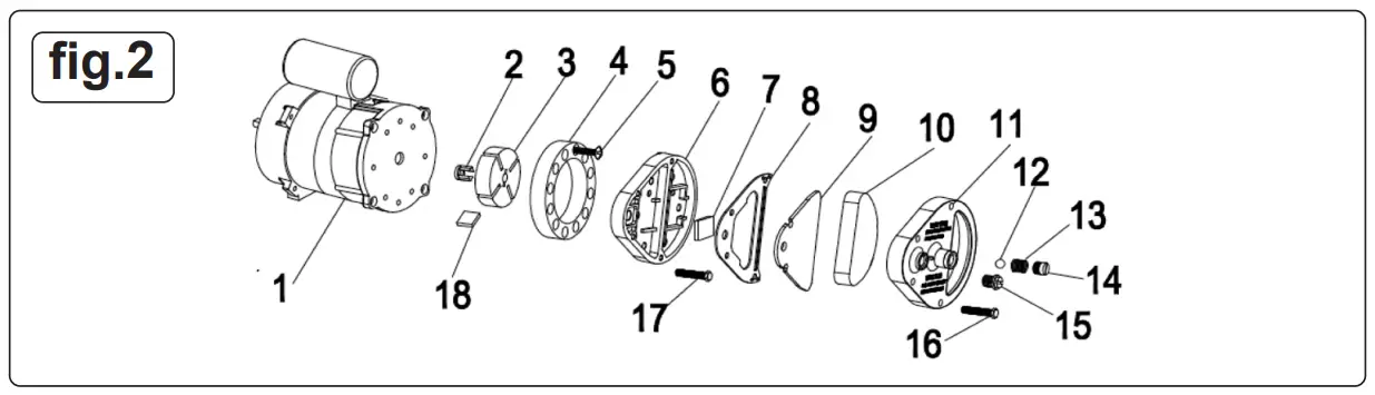
Ignition Electrodes fig.3
Clean and if necessary replace the ignition electrode. For electrode gaps see fig.3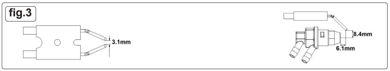
Compressor Pressure Adjustment fig.4
- WARNING! The compressor pressure is factory set and must be checked by qualified technicians only. Tampering with the unit may be dangerous.
Remove pressure gauge cap. Connect a pressure gauge on the pressure measuring port on the rear guard. Start heater and read air pressure value. If necessary adjust pressure to correct value by turning the adjusting screw (the air vent hole in the adjusting screw middle) clockwise to increase, anticlockwise to decrease the pressure.
fig.4
Model
AB1008
AB1258, AB1758
Air Pressure (bar)
0.31
0.45
TROUBLESHOOTING
| PROBLEM | CAUSE | REMEDY |
| Motor does not start E1 displayed on the screen | No power or low voltage | Check power line and voltage |
| Faulty or damaged mains cable | Check and replace if needed | |
| Faulty motor/capacitor | Check and if necessary replace | |
| Lockout of appliance due to previous overheating | Detect the cause of the overheating Shut the appliance down Check air inlet and outlet Wait a few minutes and restart the heater | |
| E2 displayed on the screen | The temperature probe is faulty or the connector for the temperature probe is loose | Check and replace the temperature probe if needed |
| Check and replace the PCB if needed | ||
| Motor runs, but the heater does not ignite and locks out after a short time E1 displayed on screen | Empty fuel tank, dirty or wrong fuel | Remove wrong or dirty fuel Fill tank with clean diesel or kerosene |
| Fuel filter clogged | Clean or replace fuel filter | |
| Air leaks on oil line | Check hoses, tighten connections, if necessary replace | |
| Burner nozzle clogged | Clean nozzle with compressed air, replace if necessary | |
| Fuel viscosity increased at low temperature | Mix diesel with 10-20% kerosene | |
| Flames come out of flue outlet E1 displayed on screen | Insufficient airflow into combustion chamber | Check air inlet, fan, motor |
| Compressor pressure too high | Check air pressure , adjust if needed* | |
| Heater stops during operation Ambient temperature displayed on the screen | The room temperature set on room thermostat has been reached | Normal operation To start turn temperature control knob clockwise onto a higher setting |
| Heater stops during operation E1 displayed on screen | Flame failure | Check and remove the cause of the malfunction To reset, turn On/Off switch to 0 and then to I Call technical service if problem persists |
| Bad combustion | ||
| Reduced airflow | ||
| Overheating | ||
| LC displayed on the screen | A 3 times failure for igniting will lock the PCB and stop operation | With mains supply connected, heater will unlock after the power switch is switched to ON 3 times in 10 seconds |
WEEE REGULATIONS
 Dispose of this product at the end of its working life in compliance with the EU Directive on Waste Electrical and Electronic Equipment (WEEE). When the product is no longer required, it must be disposed of in an environmentally protective way. Contact your local solid waste authority for recycling information.
ENVIRONMENT PROTECTION
 Recycle unwanted materials instead of disposing of them as waste. All tools, accessories and packaging should be sorted, taken to a recycling centre and disposed of in a manner which is compatible with the environment. When the product becomes completely unserviceable and requires disposal, drain any fluids (if applicable) into approved containers and dispose of the product and fluids according to local regulations.
Note: It is our policy to continually improve products and as such we reserve the right to alter data, specifications and component parts without prior notice. Please note that other versions of this product are available. If you require documentation for alternative versions, please email or call our technical team on [email protected] or 01284 757505.
Important: No Liability is accepted for incorrect use of this product.
Warranty: Guarantee is 12 months from purchase date, proof of which is required for any claim.
Support
Sealey Group, Kempson Way, Suffolk Business Park, Bury St Edmunds, Suffolk. IP32 7AR
 01284 757500
 01284 703534

Information requirements for gaseous/liquid fuel local space heaters
| Model identifier(s): AB1008.V4 | ||||||||||||||
| Indirect heating functionality: Yes | No |
| ||||||||||||
| Direct heat output: 30 (kW) | Indirect heat output: | N/A | (kW) | |||||||||||
| Fuel | Space heating emissions NOx nitrogen oxides | |||||||||||||
| Select fuel type: | Gaseous | Liquid | Specify: Kerosene | 69 | [mg/kWhinput] (GCV) | |||||||||
| Item | Symbol | Value | Unit | Item | Symbol | Value | Unit | |||||||
| Heat output | Useful efficiency (NCV) | |||||||||||||
| Nominal heat output | Pnom | 30 | kW | Useful efficiency at nominal heat output | ῃth,nom | 100 | % | |||||||
| Minimum heat output (indicative)* | Pmin | N/A | kW | Useful efficiency at minimum heat output (indicative)* | ῃth,min | N/A | % | |||||||
| Auxiliary electricity consumption | Type of heat output/room temperature control (select one) | |||||||||||||
| At nominal heat output | elmax | 0.002 | kW | Single stage heat output, no room temperature control | Yes No | |||||||||
| At minimum heat output | elmin | N/A | kW | Two or more manual stages, no room temperature control | Yes No | |||||||||
| In standby mode | elSB | N/A | kW | With mechanical thermostat room temperature control | Yes No | |||||||||
| * Enter figure or NA | With electronic room temperature control | Yes No | ||||||||||||
| With electronic room temperature control plus day timer | Yes No | |||||||||||||
| With electronic room temperature control plus week timer | Yes No | |||||||||||||
| Other control options (multiple selections possible) | ||||||||||||||
| Room temperature control, with presence detection | Yes No | |||||||||||||
| Room temperature control, with open window detection | Yes No | |||||||||||||
| With distance control option | Yes No | |||||||||||||
| With adaptive start control | Yes No | |||||||||||||
| Permanent pilot flame power requirement | With working time limitation | Yes No | ||||||||||||
| Pilot flame power required (if applicable)* | Ppilot | N/A | kW | With black bulb sensor | Yes No | |||||||||
| The seasonal space heating energy efficiency ƞs | ||||||||||||||
| Item | Symbol | Value | Unit | |||||||||||
| The seasonal space heating Energy efficiency in active mode | ƞs,on | 100 | % | |||||||||||
| The seasonal space heating energy efficiency ƞs | ƞs | 97 | % | |||||||||||
| Energy efficiency classes | A | |||||||||||||
| Contact details: Sealey Group, Kempson Way, Suffolk Business Park, Bury St Edmunds, Suffolk, IP32 7AR. www.sealey.co.uk | ||||||||||||||
| v1 | ERP Table 1 | |||||||||||||


