MSA GALLET F1XF / Cairns XF1 Communication Accessories User Manual
![]()
Operating Manual
![]()
Order No.: CH180459-PRQ10277/07
MSA Europe GmbH
Schlüsselstrasse 12
8645 Rapperswil-Jona
Switzerland
[email protected]
www.MSAsafety.com
© MSA 2022 All rights reserved
Safety Regulations
1.1 Correct Use
The following communication accessories are described in this document:
- Flexible microphone headset
- Bone conductive headset
These communication accessories are designed to be used together with the GALLET F1XF / Cairns XF1 fire-fighting helmet.
![]()
These accessories should not be used with other types of helmets or without a helmet.
The accessories provide hand-free communication capability in situations where the GALLET F1XF / Cairns XF1 helmet is likely to be used. These situations include but are not limited to structural firefighting, rescue operations, road traffic accidents.
![]()
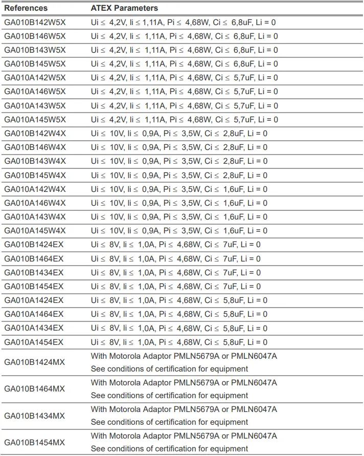
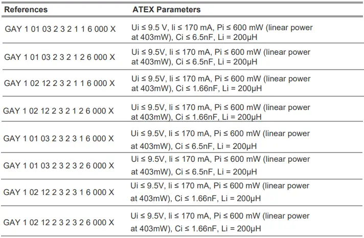
Uses in explosive atmosphere require the use of ATEX approved equipment (Check ATEX marking on sticker equipment).
ATEX GALLET F1XF / Cairns XF1 communication accessories are ATEX certified for use with ATEX certified PTT (push to talk)/RSM or radios (refer to ATEX parameters).
Before using the product in an ATEX area, it is the responsibility of the user to correctly verify the ATEX compatibility with the other interconnected systems (PTT/RSM/radios). Refer if necessary to the ATEX certificate of the products concerned. MSA disclaims any liability for the improper use.
Be aware that other configurations are not ATEX certified and must not be used in explosive areas.
It is imperative that this operating manual be read and observed when using the product. In particular, the safety instructions, as well as the information for the use and operation of the product, must be carefully read and observed. Furthermore, the national regulations applicable in the user’s country must be taken into account for safe use.
Alternative use, or use outside this specification will be considered as non-compliance. This also applies especially to unauthorized alterations to the product and to commissioning work that has not been carried out by MSA or authorized persons.
1.2 Liability Information
MSA accepts no liability in cases where the product has been used inappropriately or not as intended. The selection and use of the product are the exclusive responsibility of the individual operator.
Product liability claims, warranties also as guarantees made by MSA with respect to the product are voided, if it is not used, serviced or maintained in accordance with the instructions in this manual.
![]()
This product is supporting life and health. Inappropriate use, maintenance or servicing may affect the function of the device and thereby seriously compromise the user’s life.
Before use the product operability must be verified. The product must not be used if the function test is unsuccessful, it is damaged, a competent servicing/maintenance has not been made, genuine MSA spare parts have not been used.
Description
2.1 Overview Headsets
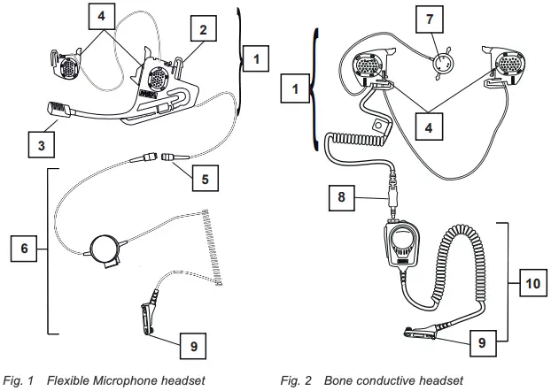
- Microphone + earphone set
- Fixing lugs
- Helmet mounted pickup / Microphone
- Loudspeaker
- Lemo plug
- Standard Gallet PTT
- Bone microphone
- Nexus plug
- Connector plug depending on the radio type
- RSM Handycom
The headsets with NEXUS plug can be connected to Push-to-talk modules with a NEXUS socket (female). The different wirings for a NEXUS 4 connection are shown below:
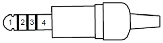
Standard Wiring
- (-) Microphone and
(-) Loudspeaker - (+) Microphone
- Not connected
- (+) Loudspeaker
NATO UK Wiring
- (-) Microphone
- (+) Microphone
- (+) Loudspeaker
- (-) Loudspeaker
NATO US Wiring
- (-) Microphone
- (+) Loudspeaker
- (+) Microphone
- (-) Loudspeaker
Installation
3.1 Flexible Microphone Headset
The headset is installed on the right side of the helmet.
(1) Insert the hook (A) into its designated slot.
(2) Push the clip (B) into its slot until it clicks.
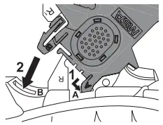
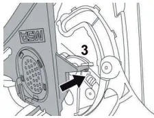
(3) Push the retention clip (3) behind the edge of the locking clip as shown.
(4) Check the attachment by gently pulling the module.
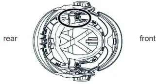
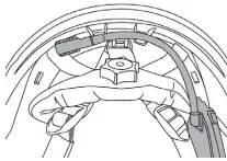
3.2 Speaker Module (Bone Conductive or Second Speaker)
Check the indication on the back of the module to position it on the proper side of the helmet (L or R).
(1) Insert the hook (A) into its designated slot.
(2) Push the clip (B) into its slot until it clicks.
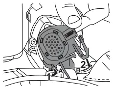
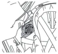
(3) For the second speaker (optional), position the module so that the connecting wire is located above the suspension straps as shown.
![]()
Ensure that the front retention strap does not obscure field of vision
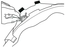
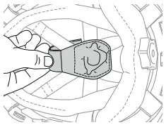
3.3 Bone Conductive Sensor
The bone conductive sensor could be placed inside the front padding of the headband or inside the leather pocket hooked to the straps of the suspension system.
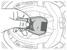
3.3.1 Installation in the Front Padding
(1) Open the front padding as shown by detaching the Velcro fasteners.
(2) Slide the bone conductive sensor inside one of the two pockets as shown.
(3) Ensure the microphone sensor is positioned towards the face.
The sensor must touch the forehead while wearing the helmet.
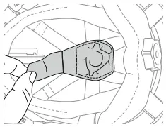
(4) Place the cable between headband and headband padding in a way to avoid any pressure points on the forehead.
(5) Fold back and close the headband by attaching the Velcro fasteners.
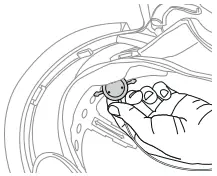
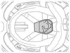
3.3.2 Installation in the Suspension System
(1) Install the bone conductive sensor in the leather pocket.
(2) Turn back the pocket on the straps of the suspension system and keep the leather strip open.
(3) Pass the leather pocket strip under the suspension straps. Close with the Velcro fastener.
(4) Put the cable between the inner cap and the suspension system straps in a way to avoid any pressure points on the head.
Use
4.1 Connection to the Communication System
![]()
The headset should be connected to the communication system before switching on the terminal. Do not disconnect the device while the radio is in use.
(1) Turn off the radio terminal.
(2) Connect the headset to the Communication system using the supplied quick release plug.
(3) Position the PTT/RSM/radio in the preferred position (belt, shoulder straps, etc.). Wearing equipment under cloths will protect them from the environment.
![]()
Keep a distance of 20 to 30 cm between the PTT/RSM and the radio module to avoid any risk of interference that may reduce communication quality.
(4) Turn on the radio terminal. Refer to Radio Terminal user’s instructions if needed.
Incoming communications are now directed to the headset loudspeaker (1 or 2 speakers).
(5) Adjust the volume on the radio to an appropriate level (or on the headset if equipped).
![]()
The devices are designed for use with 2-way radios (simplex mode).
(6) To listen to incoming messages, release the PTT/RSM push button.
(7) To speak (provided that the line is open), push the PTT push button and speak loud and clear.
(8) Release the push button once transmission is over.
4.2 Flexible Microphone Adjustment
The position of the flexible microphone can be adjusted by approximately 80 mm to properly position the microphone.
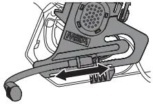
(1) Change the microphone position by sliding it gently along its mounting rail.
![]()
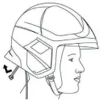
When using without a Breathing Apparatus (BA), the microphone should be positioned in front of the mouth.
When using with a BA, the microphone should be positioned in front of the speech diaphragm of the facepiece. Refer to the facepiece instructions manual to locate the speech diaphragm.
![]()
Do not carry the helmet by the flexible microphone or any of the cables of the communication accessory.
4.3 Flexible Microphone Parking Position
The device is equipped with a parking/standby position, so it can remain in the helmet without bothering the user when not in use.
(1) Push the flexible microphone all the way back, and rotate it downwards.
(2) Bend the microphone until it follows the shape of the shell as shown (inside the neck curtain if the helmet is fitted with a neck curtain).
![]()
If the communication accessories are not going to be used for extended periods MSA recommends to remove them from the helmet as the connection cable may bother the user during some operations.
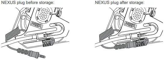
4.4 Storage of the NEXUS plug
The device is equipped with a yellow sheath giving the possibility to store the NEXUS plug when the device is not used. It avoids to bother the user when not in use.
Maintenance and Cleaning
5.1 Disassembly
(1) To disassemble the equipment from the helmet, push the clips and gently pull out the devices from the mounting slots.
5.2 Cleaning
(1) Clean with a sponge soaked in soapy water.
![]()
Do not use solvents or hydrocarbons.
Do not submerge in water.
5.3 Disposal
 When this crossed-out wheeled bin symbol is attached to a product it means the product is covered by the European Directive 2002/96/EC.
Use the available local separate collection system for electrical and electronic products.
Act according to local rules and legislations and do not dispose of used products with the normal household waste.
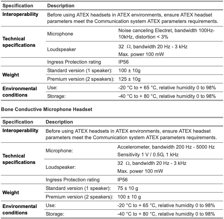
Technical Data
Flexible Microphone Headset
Marking
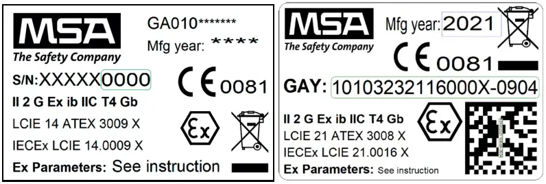
![]()
For local MSA contacts, please visit us at MSAsafety.com


