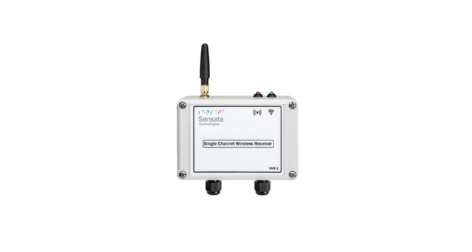
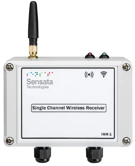
Sensata IWR-1 Series Single Channel Industrial Wireless Pressure-Temperature Receiver
Whilst every effort has been taken to ensure the accuracy of this document, we accept no responsibility for damage, injury, loss, or expense resulting from errors or omissions, and reserve the right of amendment without notice.
FCC STATEMENT
Information for users
This equipment has been tested and found to comply with the limits for a Class B device, pursuant to part 15 of the FCC Rules. These limits are designed to provide reasonable protection against harmful interference in a residential installation. This equipment generates uses and can radiate radio frequency energy, and if not installed and used in accordance with the instructions, may cause harmful interference to radio communications. However, there is no guarantee that interference will not occur in a particular installation. If this equipment does cause harmful interference to radio or television reception, which can be determined by turning the equipment off and on, the user is encouraged to try to correct the interference by one or more of the following measures:
- Reorient or relocate the receiving antenna
- Increase the separation between the equipment and the receiver
- Connect the equipment to an outlet on a circuit different from that which the receiver is connected
- Consult the dealer or an experienced radio/TV technician for help
Caution:
To satisfy FCC RF Exposure requirements for mobile and base station transmission devices, a separation distance of 20cm or more should be maintained between the antenna of this device and persons during operation. To ensure compliance operation at closer than this distance is not recommended. The antenna used for this transmitter must not be co-located or operating in conjunction with any other antenna or transmitter. No other antenna may be used with this equipment other than the PCB antenna supplied with this equipment.
INTRODUCTION
Safety Information
This manual contains information that must be observed in the interest of your safety and to avoid damage to assets. Please read this manual before installing and commissioning the device and keep the manual in an accessible location for all users. To satisfy FCC RF Exposure requirements for mobile and base station transmission devices, a separation distance of 20cm or more should be maintained between the antenna of this device and persons during operation. To ensure compliance operation at closer than this distance is not recommended. The antenna used for this transmitter must not be co-located or operating in conjunction with any other antenna or transmitter.
Hardware Features
The IWR range of Wireless Pressure & Temperature Receivers has been designed to receive the values from IWPT Wireless Pressure Transmitters and/or IWTT Wireless Temperature Transmitters and output the measured value as 4-20 mA or 1-5 V dc analog output signals. The IWR-1 has a single output. The IWR range of receiver units operates on the license-free 2.4 GHz band. Ranges of up to 500 m are possible using the standard transmitter and receiver units with the supplied antennas. The achieved ranges can be adversely affected by obstacles (particularly metals), walls, trees, vehicles, etc., in between the transmitter and receiver.
The receiver is powered by a DC voltage of between 12-32 V dc.
UNPACKING
The instrument should be carefully inspected for signs of damage that may have occurred in transit. In the unlikely case that damage has been sustained, DO NOT use the instrument, but please retain all packaging for our inspection and contact your supplier immediately.
IWR-1 RECEIVER SET-UP PROCEDURE
The IWR-1 receives data from an IWPT or IWTT wireless transmitter and produces a 4-20 mA or 1-5 V dc analog source output representing 0 – 100% of the range of the transmitter connected. It also has an alarm output that can be used as a high/low, loss of signal, or low battery alarm. As delivered the IWR-1 is configured to receive transmissions from an IWPT or IWTT wireless transmitter configured to channel 1.
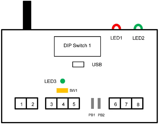
Connections and Configuration Switches
IWR-1 SERIES
PRESSURE & TEMPERATURE RECEIVERS – OPERATING MANUAL
| Terminal Number | Connection |
| 1 | Power 0V |
| 2 | Power +ve |
| 3 | Output 0V |
| 4 | mA Output +ve |
| 5 | 1-5 V dc Output +ve |
| 6 | Relay Common |
| 7 | Relay N.C |
| 8 | Relay N.O |
Dipswitch Configuration
The 8-way Dip Switch 1 is used to configure the basic functionality of the IWR-1 The RF Network code must be the same as the Transmitter to be used with the Receiver unit. Switches 1, 2, 3 & 4 select the network code as below.
RF NETWORK/1 2 3 4
| 1 | 0 | 0 | 0 | 0 |
| 2 | 0 | 0 | 0 | 1 |
| 3 | 0 | 0 | 1 | 0 |
| 4 | 0 | 0 | 1 | 1 |
| 5 | 0 | 1 | 0 | 0 |
| 6 | 0 | 1 | 0 | 1 |
| 7 | 0 | 1 | 1 | 0 |
| 8 | 0 | 1 | 1 | 1 |
| 9 | 1 | 0 | 0 | 0 |
| 10 | 1 | 0 | 0 | 1 |
| 11 | 1 | 0 | 1 | 0 |
| 12 | 1 | 0 | 1 | 1 |
| 13 | 1 | 1 | 0 | 0 |
| 14 | 1 | 1 | 0 | 1 |
| 15 | 1 | 1 | 1 | 0 |
| 16 | 1 | 1 | 1 | 1 |
Switches 5 and 6 select the number of transmissions that are missed before the Alarm relay output switches to the alarm condition or the analog output changes to its burnout condition if a burnout option is configured using the IWR-SETsoftware.
| Missed Transmissions | 5 | 6 |
| 4 | 0 | 0 |
| 2 | 0 | 1 |
| 6 | 1 | 0 |
| No Alarm | 1 | 1 |
Switches 7 and 8 configure the action of the Alarm Relay output. This can also be configured to the exact alarm values required using the USB port and the IWR-set software.
Relay Action/ 7 8
| Relay 1 switches OFF above 50% | 0 | 0 | |
| Relay 1 switches OFF above 75% | 0 | 1 | |
| Relay 1 switches OFF above 25% | 1 | 0 | |
| Relay 1 Configured via USB & IWR-Set | Software | 1 | 1 |
LED Indication
External LED 1 is used to indicate the status of the alarm relay. This is lit if the value transmitted is outside the alarm limit, the receiver has missed the number of transmissions configured above, or will flash if the transmitter has a low battery capacity. External LED 2 flashes when a valid transmission is received from a connected transmitter. The internal indicator LED3 is used to indicate the following alarm conditions: LED flashes 2 times: This indicates that the number of transmissions missed has exceeded the number set up by switches 5 & 6 above. LED flashes 3 times: This indicates that the transmitted value is outside the limits selected by switches 7 & 8 above. LED flashes 4 times: This indicates the transmitter has a low battery level.
Output Calibration and Analogue Output Scaling
The IWR-1 is factory calibrated for 4-20mA and 1-5V source outputs so that if the transmits a zero or full-scale output the IWR-1 output will be within its accuracy specifications. The output selector switch is used to select either a 4-20mA or 1-5Vdc output. Push the switch SW1 to the left to select 4-20mA and to the right to select 1-5Vdc. It is possible to adjust the output to match the equipment used to monitor the output or compensate for any zero or span drift of the transmitter. This is achieved by using the pushbuttons PB1 (DOWN) and PB2 (UP) and the internal LED as outlined here:
- Push both buttons at the same time then release to put the unit into zero-tare mode.
- LED will go amber, and the output will change to the zero value.
- Ensure there is no pressure/temperature applied to the connected transmitter and then use the DOWN and UP buttons to adjust the output to be 4mA or 1V
- If the led flashes amber this indicates that the connected transmitter’s zero value is not valid
- Push both buttons at the same time again and then release.
- LED will go red to indicate that the full-scale output will be adjusted. Inject the full-scale pressure or temperature range into the transmitting sensor using a Calibrator. If no Calibrator is available press both buttons again to exit the calibration saving only the zero tare. The LED will go amber for 0.5 seconds as the zero tare value is learned and saved to memory.
- If the full-scale transmitter range can be applied using the DOWN and UP buttons to adjust the output to be 20mA or 5V. When the output is correct push both buttons at the same time then release.
- If the LED flashes RED this indicates that the measured value is not close enough to the expected full-scale value to allow successful calibration.
- If full-scale calibration has been achieved the led will go amber for 0.5 seconds as calibration values are learned and saved to memory.
The saved values will now be used to produce the calibrated analog output. The analog output can be scaled to any part of the full-scale range of the transmitter connected.
For example, an IWTT with a P100 input sends a temperature back between -200°C & 800°C. By default, the 4-20 mA output will be at 4 mA at -200°C and 20 mA ay +800°C. the IWR-Set V2.1 software can be used to scale the 4-20 mA so that 4 mA is output at a temperature of 0°C and 20 mA is output at a temperature of +500°C. The setup procedure is intuitive once the IWR-SET software is opened on a PC and connected to the IWR receiver using a standard micro USB cable. If switches 5 & 6 are configured to switch the Alarm Relay if wireless transmissions are missed the analog output can also be set to go to a failsafe burnout output if no transmissions are received. If a 4-20 mA output is selected the output will go to 2.2 mA if Low Burnout is selected or 22.8 mA if High Burnout is selected. If No Action (the default setting) is selected the analog output will stay at the last valid value received from the connected transmitter.
TROUBLESHOOTING GUIDE
| Problem encountered | Possible Causes |
| LED2 doesn’t flash | The IWR receiver is not connected to a transmitter or the transmitter is out of range. |
| mA Output reads zero | The IWR receiver output is not wired correctly, check the wiring and try again |
| Output from the IWR receiver isn’t equivalent to the transmitter range being monitored | Check that the IWR receiver is linked to the correct transmitter by pressing the push button inside the transmitter and checking that LED2 on the receiver flashes when the transmitter button is pressed. If the output still doesn’t agree with the reading, re-calibrate the unit as described above. |
| LED1 is solid ON | This indicates that the reading from the transmitter is outside the limit selected or the receiver is out of range of the transmitter and transmissions are not being received. |
| LED1 is flashing | This indicates that the battery inside the transmitter is running low. Change the battery inside the transmitter taking care to exactly follow the procedure outlined in the transmitter manual. |
SYSTEM PART NUMBERS
| Pressure Transmitters | |
| Part Number | Pressure Range |
| IWPT-G1000-00 | 0-1 Bar g |
| IWPT-G6000-00 | 0-6 Bar g |
| IWPT-GM1P9-00 | -1-+9 Bar g |
| IWPT-G1002-00 | 0-10 Bar g |
| IWPT-G1602-00 | 0-16 Bar g |
| IWPT-CO184-00 | -1-+24 Bar g |
| IWPT-G2502-00 | 0-25 Bar g |
| IWPT-G4002-00 | 0-40 Bar g |
| IWPT-G1003-00 | 0-100 Bar g |
| IWPT-G2503-00 | 0-250 Bar g |
| IWPT-G4003-00 | 0-400 Bar g |
| IWPTU-GP015-00 | 0-15 psi g |
| IWPTU-GP030-00 | 0-30 psi g |
| IWPTU-CO446-00 | -14.5 to +150 psi g |
| IWPTU-GP075-00 | 0-75 psi g |
| IWPTU-GP100-00 | 0-100 psi g |
| IWPTU-CO447-00 | -14.5 to +350 psi g |
| IWPTU-GP150-00 | 0-150 psi g |
| IWPTU-GP300-00 | 0-300 psi g |
| IWPTU-GP750-00 | 0-750 psi g |
| IWPTU-GP1K5-00 | 0-1500 psi g |
| IWPTU-GP3K6-00 | 0-3600 psi g |
| IWPTU-GP5K8-00 | 0-5800 psi g |
| IWPTL-G0050-00 | 0-50mbar G |
| IWPTL-G0100-00 | 0-100mbar G |
| IWPTL-G0250-00 | 0-250mbar G |
| IWPTL-G0500-00 | 0-500mbar G |
| IWPTL-G0750-00 | 0-750mbar G |
| IWPTL-G1000-00 | 0-1000mbar G |
| IWPTL-G0500-00 | 0-500mbar Abs |
| IWPTL-G0750-00 | 0-750mbar Abs |
| IWPTL-G1000-00 | 0-1000mbar Abs |
| IWPTLU-GP001-00 | 0-1 psi g |
| IWPTLU-GP002-00 | 0-2 psi g |
| IWPTLU-GP005-00 | 0-5 psi g |
| IWPTLU-GP008-00 | 0-8 psi g |
| IWPTLU-GP010-00 | 0-10 psi g |
| IWPTLU-GP015-00 | 0-15 psi g |
| IWPTLU-GP005-00 | 0-5 psi Abs |
| IWPTLU-GP010-00 | 0-10 psi Abs |
| IWPTLU-GP015-00 | 0-15 psi Abs |
| Temperature Transmitters | |
| Part Number | Transmitter Type |
| IWTTP100A | PT100 6x100mm 1/4″BSP |
| IWTTP150A | PT100 6x150mm 1/4″BSP |
| IWTTP200A | PT100 6x200mm 1/4″BSP |
| IWTTP250A | PT100 6x250mm 1/4″BSP |
| IWTTP300A | PT100 6x300mm 1/4″BSP |
| IWTTP400A | PT100 6x400mm 1/4″BSP |
| IWTTJ200A | J type 6x200mm 1/4″BSP |
| IWTTJ300A | J type 6x300mm 1/4″BSP |
| IWTTJ400A | J type 6x400mm 1/4″BSP |
| IWTTK150A | K type 6x150mm 1/4″BSP |
| IWTTK200A | K type 6x200mm 1/4″BSP |
| IWTTK300A | K type 6x300mm 1/4″BSP |
| IWTTK400A | K type 6x400mm 1/4″BSP |
| IWTTUP100A | PT100 6x100mm 1/4″NPT |
| IWTTUP150A | PT100 6x150mm 1/4″NPT |
| IWTTUP200A | PT100 6x200mm 1/4″NPT |
| IWTTUP250A | PT100 6x250mm 1/4″NPT |
| IWTTUP300A | PT100 6x300mm 1/4″NPT |
| IWTTUP400A | PT100 6x400mm 1/4″NPT |
| IWTTUJ200A | J type 6x200mm 1/4″NPT |
| IWTTUJ300A | J type 6x300mm 1/4″NPT |
| IWTTUJ400A | J type 6x400mm 1/4″NPT |
| IWTTUK150A | K type 6x150mm 1/4″NPT |
| IWTTUK200A | K type 6x200mm 1/4″NPT |
| IWTTUK300A IWTTUK400A | K type 6x300mm 1/4″NPT K type 6x400mm 1/4″NPT |
| Part Number | Number of Output Channels |
| IWR-1 | One |
| IWR-5 | Five |
| IANT-3 | 3dBi Antenna |
| IWPT-SA | Swivel adaptor (1/4” BSP) for pressure transmitters only |
SPECIFICATIONS
| System Performance | |
| Accuracy (non-linearity & hysteresis | <±0.25% / FS (BFSL) |
| Setting Errors | Zero & Full Scale,<±0.5% / FS |
| Operating Temperature | -20 to +50 °C |
| Storage Temperature | -20 to +80 °C |
| Outputs | 4-20 mA current source 1-5 V dc voltage source |
| Relay | 5A rated changeover contact |
| Enclosure Material | Light Grey ABS (RAL 7035) |
| Weight | 215 g |
| RF Transmitter | Contains FCC W&)MRF24J40MDME |
| Power Requirements | 12 to 32 V dc |
| Fuse | Built-in resettable fuse |
| Dimensions | 120mm x 80mm x 57mm (L x W x D) |
| Mounting | Any Orientation |
Sensata Technologies, Inc. (“Sensata”) data sheets are solely intended to assist designers (“Buyers”) who are developing systems that incorporate Sensata products (also referred to herein as “components”). Buyer understands and agrees that Buyer remains responsible for using its independent analysis, evaluation and judgment in designing Buyer’s systems and products. Sensata data sheets have been created using standard laboratory conditions and engineering practices. Sensata has not conducted any testing other than that specifically described in the published documentation for a particular datasheet. Sensata may make corrections, enhancements, improvements and other changes to its data sheets or components without notice. Buyers are authorized to use Sensata data sheets with the Sensata component(s) identified in each particular datasheet.
HOWEVER, NO OTHER LICENSE, EXPRESS OR IMPLIED, BY ESTOPPEL OR OTHERWISE TO ANY OTHER SENSATA INTELLECTUAL PROPERTY RIGHT, AND NO LICENSE TO ANY THIRD PARTY TECHNOLOGY OR INTELLECTUAL PROPERTY RIGHT, IS GRANTED HEREIN. SENSATA DATA SHEETS ARE PROVIDED “AS IS”. SENSATA MAKES NO WARRANTIES OR REPRESENTATIONS WITH REGARD TO THE DATA SHEETS OR USE OF THE DATA SHEETS, EXPRESS, IMPLIED OR STATUTORY, INCLUDING ACCURACY OR COMPLETENESS. SENSATA DISCLAIMS ANY WARRANTY OF TITLE AND ANY IMPLIED WARRANTIES OF MERCHANTABILITY, FITNESS FOR A PARTICULAR PURPOSE, QUIET ENJOYMENT, QUIET POSSESSION, AND NON-INFRINGEMENT OF ANY THIRD-PARTY INTELLECTUAL PROPERTY RIGHTS WITH REGARD
TO SENSATA DATA SHEETS OR USE THEREOF.
All products are sold subject to Sensata’s terms and conditions of sale supplied at www.sensata.com SENSATA ASSUMES NO LIABILITY FOR APPLICATIONS ASSISTANCE OR THE DESIGN OF BUYERS’ PRODUCTS. BUYER ACKNOWLEDGES AND AGREES THAT IT IS SOLELY RESPONSIBLE FOR COMPLIANCE WITH ALL LEGAL, REGULATORY AND SAFETY-RELATED REQUIREMENTS CONCERNING ITS PRODUCTS, AND ANY USE OF SENSATA COMPONENTS IN ITS APPLICATIONS, NOTWITHSTANDING ANY APPLICATIONS-RELATED INFORMATION OR SUPPORT THAT MAY BE PROVIDED BY SENSATA.
Mailing Address: Sensata Technologies, Inc., 529 Pleasant Street, Attleboro, MA 02703, USA.
CONTACT US
EUROPE
+44 (0)1202 897969
[email protected]
Cynergy3 Components Ltd. 7 Cobham Road, Ferndown Industrial Estate, Wimborne, Dorset, BH21 7PE, United Kingdom
USA
+1 310 561 8092 / +1 866 258 5057
[email protected].


