
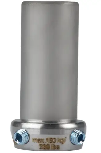
ottobock 4R72=D Long 30mm Connection Adapter
Product description
INFORMATION
Date of last update: 2021-07-19
- Please read this document carefully before using the product and observe the safety notices.
- Instruct the user in the safe use of the product.
- Please contact the manufacturer if you have questions about the product or in case of problems.
- Report each serious incident related to the product to the manufacturer and to the relevant authority in your country. This is particularly important when there is a decline in the health state.
- Please keep this document for your records.
Construction and Function
Connection adapters provide the connection between a tube clamp and a pyramid adapter or pyramid receiver. They differ in diameter, in length, and in the connection.
| Article numbers | Connection | Diameter |
| 4R72=D | Pyramid receiver | 30 mm |
| 4R72=D-62 | Pyramid receiver | 30 mm |
| Article numbers | Connection | Diameter |
| 4R75=D-70 | Pyramid receiver | 34 mm |
| 4R84=D | Pyramid adapter | 30 mm |
| 4R84=D-62 | Pyramid adapter | 30 mm |
Combination possibilities
This prosthetic component is compatible with Ottobock’s system of modular connectors. Functionality with components of other manufacturers that have compatible modular connectors has not been tested.
Intended use
Indications for use
The product is intended exclusively for lower limb exoprosthetic fittings.
Area of application
Approved for a body weight of up to 150 kg.
Environmental conditions
Storage and transport
Temperature range –20 °C to +60 °C (–4 °F to +140 °F), relative humidity 20 % to 90 %, no mechanical vibrations or impacts. 4R72=D, 4R72=D-62, 4R75=D-70, 4R84=D-62.
Allowable environmental conditions
- Temperature range: –10 °C to +45 °C (14 °F to 113 °F)
- Moisture: relative humidity: 20% to 90%, non-condensing
- Chemicals/liquids: fresh water as dripping water, occasional contact with salty air (e.g. near the ocean)
- Solids: dust
Prohibited environmental conditions
Chemicals/moisture: salt water, perspiration, urine, acids, soapsuds, chlorine water.
Prohibited environmental conditions
Solids: dust in high concentrations (e.g. construction site), sand, highly hygroscopic particles (e.g. talcum)
4R84=D
Allowable environmental conditions
- Temperature range: –10 °C to +45 °C (14 °F to 113 °F)
- Chemicals/liquids: fresh water, salt water, perspiration, urine, soapsuds, chlorine water
- Moisture: Submersion: max. 1 h in 3 m depth, relative humidity: no restrictions
- Solids: Dust, occasional contact with sand Clean the product after contact with humidity/chemicals/ solids, in order to avoid increased wear and damage (see page 10).
Unallowable environmental conditions
- Solids: Highly hygroscopic particles (e.g. talcum), continuous contact with sand
- Chemicals/liquids: Acids, continuous use in liquid media.
Lifetime
This product was tested by the manufacturer with 3 million load cycles. Depending on the user’s activity level, this corresponds to a maximum lifetime of 5 years.
Safety
Explanation of warning symbols
CAUTION Warning regarding possible risks of accident or injury.
NOTICE Warning regarding possible technical damage.
General safety instructions
CAUTION! Risk of injury and risk of product damage
- Comply with the product’s field of application and do not expose it to excessive strain (see page 7).
- Note the combination possibilities/combination exclusions in the instructions for use of the products.
- Observe the maximum lifetime of the product.
- To prevent mechanical damage, use caution when working with the product.
- If you suspect the product is damaged, check it for proper function and readiness for use.
- Do not use the product if its functionality is restricted. Take suitable measures (e.g. cleaning, repair, replacement, inspection by the manufacturer or a specialist workshop).
NOTICE!
Risk of product damage and limited functionality
- Do not expose the product to prohibited environmental conditions.
- Check the product for damage if it has been exposed to prohibited environmental conditions.
- Do not use the product if it is damaged or in a questionable condition. Take suitable measures (e.g. cleaning, repair, replacement, inspection by the manufacturer or a specialist workshop). Signs of changes in or loss of functionality during use Among other factors, changes in functionality can be indicated by an altered gait pattern, a change in the positioning of the prosthetic components relative to each other and by the development of noises.
Scope of delivery
| Fig. | Quantity | Designation | Reference number |
| – | 1 | Instructions for use | – |
| – | 1 | Adapter | – |
| For 44R72=D, 4R72=D-62, 4R75=D-70 | |||
| – | 4 | Set screw | 506G3=M8x12-V |
Preparing the product for use
CAUTION:
Incorrect alignment or assembly
Risk of injury due to damaged prosthetic components. Observe the alignment and assembly instructions.
CAUTION:
Improper assembly of the screw connections Risk of injury due to breakage or loosening of the screw connections
- Clean the threads before every installation.
- Apply the specified torque values.
- Follow the instructions regarding the length of the screws and about how to secure the screws.
Adjusting the adapter
CAUTION
Incorrect processing of tube. Fall due to damage to the tube
- Do not clamp the tube into a vice.
- To shorten the tube, use only a tube cutter or a cutting device.
CAUTION
Incorrect mounting of the tube
Risk of injury due to breakage of load-bearing components Slide the tube all the way to the stop in the intended prosthetic component when mounting.
The 4R72=D-62, 4R75=D-70, and 4R84=D-62 connection adapters must be shortened according to the measures of the patient.
Required materials: 719R3 tube cutter or 704Y14* cutting device, 718R1 tube deburrer
- Shorten the tube to the required length.
- Deburr the inside and outside of the cut edge with the tube deburrer.
Installation in the modular prosthesis
Mounting on tube clamp adapter
Connect the connection adapter to the tube clamp adapter as described in the instructions for use of the tube clamp adapter.
Connecting the pyramid adapter and pyramid receiver
The pyramid adapter is fixed with the set screws of the pyramid receiver.
Required materials: torque wrench (e.g. 710D20), 636K13 Loctite 241
- Fitting:
Screw in the set screws. Use the torque wrench to tighten the set screws (10 Nm). - Definitive assembly:
Secure the set screws with Loctite. Screw in the set screws. Pre-tighten the set screws with the torque wrench (10 Nm) and then tighten them (15 Nm). - Replace any set screws that are protruding or are recessed too much with appropriate set screws (see selection chart).
Selection table for set screws Reference number Length (mm) 506G3=M8X12-V 12 506G3=M8X14 14 506G3=M8X16 16
Alignment
The set screws in the pyramid receiver can be used to make static adjustments during alignment, trial fittings and after the prosthesis is finished.
Replacement and disassembly
The set position of the prosthetic component can be maintained during replacement or disassembly. In order to do this, unscrew the two set screws that are screwed in the furthest and located next to each other.
Cleaning
- Clean the product with a damp, soft cloth.
- Dry the product with a soft cloth.
- Allow to air dry in order to remove residual moisture.
Maintenance
- A visual inspection and functional test of the prosthetic components should be performed after the first 30 days of use.
- Inspect the entire prosthesis for wear during normal consultations.
- Conduct annual safety inspections.
Disposal
In some jurisdictions it is not permissible to dispose of the product with unsorted household waste. Improper disposal can be harmful to health and the environment. Observe the information provided by the responsible authorities in your country regarding return, collection and disposal procedures.
Legal information
All legal conditions are subject to the respective national laws of the country of use and may vary accordingly.
Liability
The manufacturer will only assume liability if the product is used in accordance with the descriptions and instructions provided in this document. The manufacturer will not assume liability for damage caused by disregarding the information in this document, particularly due to improper use or unauthorised modification of the product.
CE conformity
The product meets the requirements of Regulation (EU) 2017/745 on medical devices. The CE declaration of conformity can be downloaded from the manufacturer’s website.
Warranty
The manufacturer warrants this device from the date of purchase. The warranty covers defects that can be proven to be a direct result of flaws in the material, production or construction and that are reported to the manufacturer within the warranty period. Further information on the warranty terms and conditions can be obtained from the competent manufacturer distribution company.
Technical data
| Reference num ber | 4R72 =D | 4R72= D-62 | 4R75= D-70 | 4R84 =D | 4R84= D-62 |
| Weight [g] | 70 | 150 | 170 | 65 | 145 |
| System height [mm] | 66 | – | – | 19 | – |
| Min. system height [mm] | – | 67 | 76 | – | 20 |
| Max. system height [mm] | – | 96 | 106 | – | 48 |
| Min. build height [mm] | 21 | 21 | 25 | 10 | 10 |
| Reference num ber | 4R72 =D | 4R72= D-62 | 4R75= D-70 | 4R84 =D | 4R84= D-62 |
| Overall height [mm] | 47 | 76 | 89 | 52 | 81 |
| Diameter [mm] | 30 | 30 | 34 | 30 | 30 |
| Material | Titani um | Stain less steel | Stain less steel | Titani um | Stain less steel |
| Max. body weight [kg] | 150 | ||||


