WEN 6502 BELT & DISC SANDER 4.3-AMP
NEED HELP? CONTACT US!
Have product questions? Need technical support? Please feel free to contact us:
- 1-800-232-1195 (M-F 8AM-5PM CST)
- [email protected]
IMPORTANT: Your new tool has been engineered and manufactured to WEN’s highest standards for dependability, ease of operation, and operator safety. When properly cared for, this product will supply you years of rugged, trouble-free performance. Pay close attention to the rules for safe operation, warnings, and cautions. If you use your tool properly and for its intended purpose, you will enjoy years of safe, reliable service.
For replacement parts and the most up-to-date instruction manuals, visit WENPRODUCTS.COM
INTRODUCTION
Thanks for purchasing the WEN Belt and Disc Sander. We know you are excited to put your tool to work, but first, please take a moment to read through the manual. Safe operation of this tool requires that you read and understand this operator’s manual and all the labels affixed to the tool. This manual provides information regarding potential safety concerns, as well as helpful assembly and operating instructions for your tool.
- SAFETY ALERT SYMBOL: Indicates danger, warning, or caution. The safety symbols and the explanations with them deserve your careful attention and understanding. Always follow the safety precautions to reduce the risk of fire, electric shock or personal injury. However, please note that these instructions and warnings are not substitutes for proper accident prevention measures.
- NOTE: The following safety information is not meant to cover all possible conditions and situations that may occur. WEN reserves the right to change this product and specifications at any time without prior notice.
- At WEN, we are continuously improving our products. If you find that your tool does not exactly match this manual, please visit wenproducts.com for the most up-to-date manual or contact our customer service at 1-800-232-1195.
- Keep this manual available to all users during the entire life of the tool and review it frequently to maximize safety for both yourself and others.
SPECIFICATIONS
| Model Number | 6502, 6502T |
| Motor | 120V, 60 Hz, 4.3A |
| Motor / Disc Speed | 3600 RPM (No Load) |
| Disc Diameter | 6 Inches |
| Belt Size | 4 x 36 Inches |
| Belt Speed | 1900 FPM (No Load) |
| Belt Bed Tilt | 0° to 90° |
| Included Belt Grit | 80 |
| Dust Port Size | 2-1/4 Inches |
| Net Weight | 41 lbs. |
| Product Dimensions | 17.9″ x 15.0″ x 11.2″ |
GENERAL SAFETY RULES
WARNING! Read all safety warnings and all instructions. Failure to follow the warnings and instructions may result in electric shock, fire and/or serious injury.
Safety is a combination of common sense, staying alert and knowing how your item works. The term “power tool” in the warnings refers to your mains-operated (corded) power tool or battery-operated (cordless) power tool.
SAVE THESE SAFETY INSTRUCTIONS.
WORK AREA SAFETY
- Keep work area clean and well lit. Cluttered or dark areas invite accidents.
- Do not operate power tools in explosive atmo-spheres, such as in the presence of flammable liquids, gases or dust. Power tools create sparks which may ig-nite the dust or fumes.
- Keep children and bystanders away while operating a power tool. Distractions can cause you to lose control.
ELECTRICAL SAFETY
- Power tool plugs must match the outlet. Never mod-ify the plug in any way. Do not use any adapter plugs with earthed (grounded) power tools. Unmodified plugs and matching outlets will reduce risk of electric shock.
- Avoid body contact with earthed or grounded surfac-es such as pipes, radiators, ranges and refrigerators. There is an increased risk of electric shock if your body is earthed or grounded.
- Do not expose power tools to rain or wet conditions. Water entering a power tool will increase the risk of elec-tric shock.
- Do not abuse the cord. Never use the cord for car-rying, pulling or unplugging the power tool. Keep cord away from heat, oil, sharp edges or moving parts. Damaged or entangled cords increase the risk of electric shock.
- When operating a power tool outdoors, use an ex-tension cord suitable for outdoor use. Use of a cord suitable for outdoor use reduces the risk of electric shock.
- If operating a power tool in a damp location is un-avoidable, use a ground fault circuit interrupter (GFCI) protected supply. Use of a GFCI reduces the risk of elec-tric shock.
PERSONAL SAFETY
- Stay alert, watch what you are doing and use com-mon sense when operating a power tool. Do not use a power tool while you are tired or under the influence of drugs, alcohol or medication. A moment of inatten-tion while operating power tools may result in serious personal injury.
- Use personal protective equipment. Always wear eye protection. Protective equipment such as a respira-tory mask, non-skid safety shoes and hearing protection used for appropriate conditions will reduce the risk of personal injury.
- Prevent unintentional starting. Ensure the switch is in the off-position before connecting to power source and/or battery pack, picking up or carrying the tool. Carrying power tools with your finger on the switch or energizing power tools that have the switch on invites accidents.
- Remove any adjusting key or wrench before turning the power tool on. A wrench or a key left attached to a rotating part of the power tool may result in personal injury.
- Do not overreach. Keep proper footing and balance at all times. This enables better control of the power tool in unexpected situations.
- Dress properly. Do not wear loose clothing or jew-elry. Keep your hair and clothing away from moving parts. Loose clothes, jewelry or long hair can be caught in moving parts.
WARNING! Read all safety warnings and all instructions. Failure to follow the warnings and instructions may result in electric shock, fire and/or serious injury.
Safety is a combination of common sense, staying alert and knowing how your item works. The term “power tool” in the warnings refers to your mains-operated (corded) power tool or battery-operated (cordless) power tool.
SAVE THESE SAFETY INSTRUCTIONS. - If devices are provided for the connection of dust extraction and collection facilities, ensure these are connected and properly used. Use of dust collection can reduce dust-related hazards.
POWER TOOL USE AND CARE
- Do not force the power tool. Use the correct power tool for your application. The correct power tool will do the job better and safer at the rate for which it was designed.
- Do not use the power tool if the switch does not turn it on and off. Any power tool that cannot be controlled with the switch is dangerous and must be repaired.
- Disconnect the plug from the power source and/or the battery pack from the power tool before making any adjustments, changing accessories, or storing power tools. Such preventive safety measures reduce the risk of starting the power tool accidentally.
- Store idle power tools out of the reach of children and do not allow persons unfamiliar with the power tool or these instructions to operate the power tool. Power tools are dangerous in the hands of untrained us-ers.
- Maintain power tools. Check for misalignment or binding of moving parts, breakage of parts and any other condition that may affect the power tool’s opera-tion. If damaged, have the power tool repaired before use. Many accidents are caused by poorly maintained power tools.
- Keep cutting tools sharp and clean. Properly main-tained cutting tools with sharp cutting edges are less likely to bind and are easier to control.
- Use the power tool, accessories and tool bits, etc. in accordance with these instructions, taking into ac-count the working conditions and the work to be per-formed. Use of the power tool for operations different from those intended could result in a hazardous situa-tion.
- Use clamps to secure your workpiece to a stable surface. Holding a workpiece by hand or using your body to support it may lead to loss of control.
- KEEP GUARDS IN PLACE and in working order.
SERVICE
Have your power tool serviced by a qualified repair person using only identical replacement parts. This will ensure that the safety of the power tool is main-tained.
CALIFORNIA PROPOSITION 65 WARNING
Some dust created by power sanding, sawing, grinding, drilling, and other construction activities may contain chemicals, including lead, known to the State of Califor-nia to cause cancer, birth defects, or other reproductive harm. Wash hands after handling. Some examples of these chemicals are:
- Lead from lead-based paints.
- Crystalline silica from bricks, cement, and other masonry products.
- Arsenic and chromium from chemically treated lumber.
Your risk from these exposures varies depending on how often you do this type of work. To reduce your ex-posure to these chemicals, work in a well-ventilated area with approved safety equipment such as dust masks specially designed to filter out microscopic particles.
BELT SANDER SAFETY WARNINGS
WARNING! Do not operate the power tool until you have read and understood the following instructions and the warning labels.
BELT SANDER SAFETY
- This sander is designed to sand wood or wood-like products only. Sanding or grinding other materials could result in fire, injury, or damage to the workpiece.
- Use the sander on horizontal surfaces only. Operating the sander when mounted on non-horizontal surfaces may result in motor damage or injury.
- Fasten the sander securely to a bench top or support-ing surface in order to stop it from tipping over or mov-ing when in use.
- Make sure the sanding belt is installed in the correct direction. See directional arrow on back of belt.
- Always have the tracking adjusted properly so the belt does not run off the pulleys.
- Do not use sanding belts or discs that are damaged, torn, or loose. Use only correct size sanding belt and disc.
- Always hold the workpiece firmly when sanding. Keep hands away from sanding belt or disc. Sand only one workpiece at a time.
- Always hold the workpiece firmly on the table when using the disc sander and when using the belt sander.
- Always sand on the downward side of the sanding disc when using the disc sander. Sanding on the upward side of the disc can cause the workpiece to fly out of position, resulting in injury.
- Always maintain a minimum clearance of 1/16 inch (1.6 mm) or less between the table or backstop and the sanding belt or disc.
- Do not sand pieces of material that are too small to be safely supported.
- When sanding a large workpiece, provide additional table height support.
- Do not sand with the workpiece unsupported. Sup-port the workpiece with the backstop or table. The only exception is curved work performed on the outer sand-ing drum.
- Always remove scrap pieces and other objects from the table, backstop, or belt before turning the sander ON.
- Never perform layout, assembly or set-up work on the table while the sander is operating.
- Never use solvents to clean plastic parts. Solvents could dissolve or otherwise damage the material. Use only a soft damp cloth to clean plastic parts.
- Should any component of your sander be missing/damaged or fail in any way, shut off switch and remove plug from power supply outlet. Replace the missing, damaged, or failed parts before resuming operation.
- Never pull the power cord out of the receptacle. Keep cords away from heat, oil, and sharp edges.
- Have an electrician replace or repair damaged or worn cords immediately.
ELECTRICAL INFORMATION
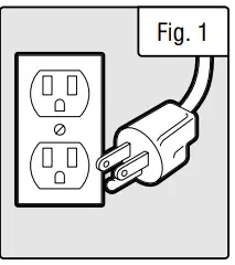
GROUNDING INSTRUCTIONS
In the event of a malfunction or breakdown, grounding provides the path of least resistance for an electric current and reduces the risk of electric shock. This tool is equipped with an electric cord that has an equipment grounding conductor and a grounding plug. The plug MUST be plugged into a matching outlet that is properly installed and grounded in accordance with ALL local codes and ordinances.
- Do not modify the plug provided. If it will not fit the outlet, have the proper outlet installed by a licensed electri-cian.
- Improper connection of the equipment grounding conductor can result in electric shock. The conductor with the green insulation (with or without yellow stripes) is the equipment grounding conductor. If repair or replacement of the electric cord or plug is necessary, DO NOT connect the equipment grounding conductor to a live terminal.
- Check with a licensed electrician or service personnel if you do not completely under-stand the grounding instructions or whether the tool is properly grounded.
- Use only three-wire extension cords that have three-pronged plugs and outlets that accept the tool’s plug. Repair or replace a damaged or worn cord immediately.

CAUTION! In all cases, make certain the outlet in question is properly grounded. If you are not sure, have a licensed electrician check the outlet.
GUIDELINES AND RECOMMENDATIONS FOR EXTENSION CORDS
When using an extension cord, be sure to use one heavy enough to carry the current your product will draw. An undersized cord will cause a drop in line voltage resulting in loss of power and overheating. The table below shows the correct size to be used according to cord length and ampere rating. When in doubt, use a heavier cord. The smaller the gauge number, the heavier the cord.
| AMPERAGE | REQUIRED GAUGE FOR EXTENSION CORDS | |||
| 25 ft. | 50 ft. | 100 ft. | 150 ft. | |
| 4.3A | 18 gauge | 16 gauge | 16 gauge | 14 gauge |
- Examine extension cord before use. Make sure your extension cord is properly wired and in good condition. Always replace a damaged extension cord or have it repaired by a qualified person before using it.
- Do not abuse extension cord. Do not pull on cord to disconnect from receptacle; always disconnect by pulling on plug. Disconnect the extension cord from the receptacle before disconnecting the product from the extension cord. Protect your extension cords from sharp objects, excessive heat and damp/wet areas.
- Use a separate electrical circuit for your tool. This circuit must not be less than a 12-gauge wire and should be protected with a 15A time-delayed fuse. Before connecting the motor to the power line, make sure the switch is in the OFF position and the electric current is rated the same as the current stamped on the motor nameplate. Running at a lower voltage will damage the motor.
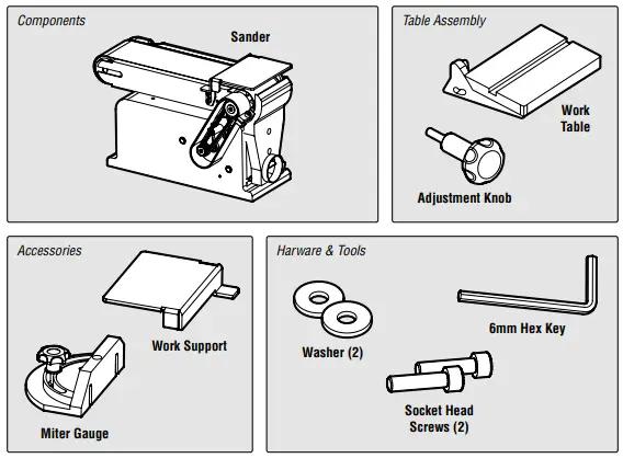
UNPACKING & PACKING LIST
UNPACKING
With the help of a friend or trustworthy foe, such as one of your in-laws, carefully remove the belt and disc sander from the packaging and place it on a sturdy, flat surface. Make sure to take out all contents and accessories. Do not discard the packaging until everything is removed. Check the packing list below to make sure you have all of the parts and accessories. If any part is missing or broken, please contact customer service at 1-800-232-1195 (M-F 8-5 CST), or email [email protected].
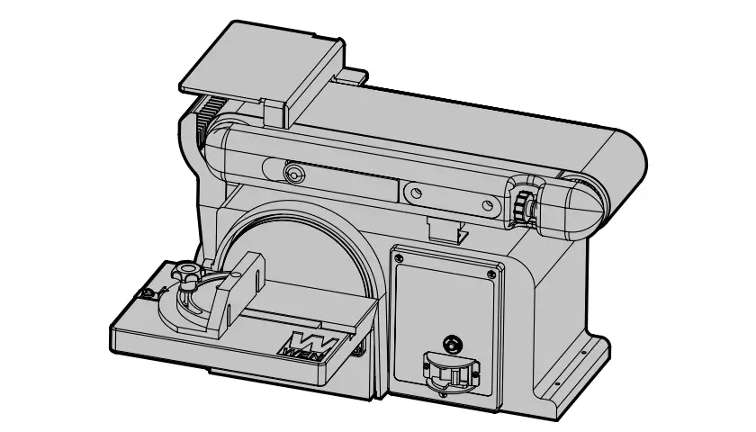
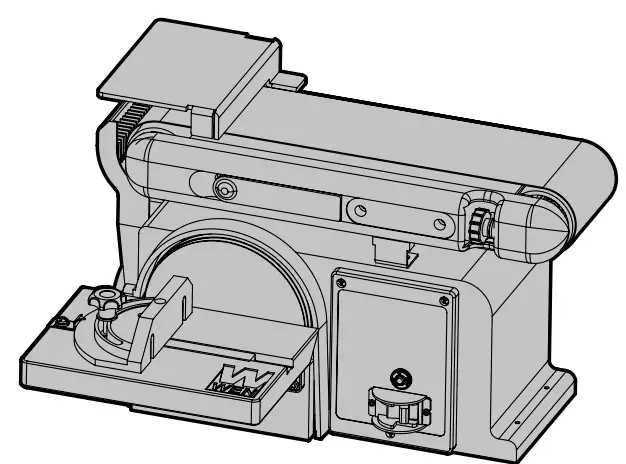
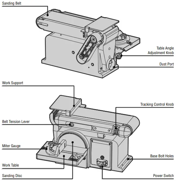
KNOW YOUR BELT & DISC SANDER
TOOL PURPOSE
Sand, smooth, and remove jagged edges with your WEN Belt and Disc Sander. Refer to the following diagrams to become familiarized with all the parts and controls of your belt and disc sander. The components will be referred to later in the manual for assembly and operation instructions.
ASSEMBLY & ADJUSTMENTS
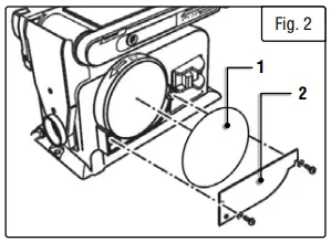
- INSTALLATION OF SANDING DISC & GUARD
- Peel backing away from sanding disc (Fig. 2 – 1).
- Align perimeter of disc with plate, and press disc firmly into position on plate, leaving no loose edges.
- Position disc guard (Fig. 2 – 2) against lower 1/3 of disc, aligning holes as shown. Use a screwdriver to fasten the pro-vided screws and washers securely.

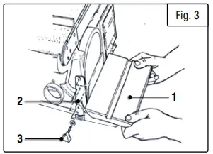
- MOUNT THE DISC SANDER TABLE
- With the table (Fig. 3 – 1) in a horizontal position, line up and insert the pivot indexing pin (Fig. 3 – 2) with the pivot hole on the frame. Hold in place.
- Insert the table lock knob (Fig. 3 – 3) into the threaded hole and tighten.
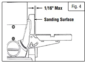
- Adjust the table so that the edge is a maximum of 1/16 inch from the disc. (Fig. 4)


NOTE: If needed, make minor adjustments to the position of the table by loosening the three bolts that appear on the underside of the table. Once the desired clearance is achieve, retighten these three bolts.
WARNING! To avoid trapping the workpiece or fingers between the table and the sanding disc, the table edge should be adjusted to a maximum of 1/16 inch from the sanding disc.
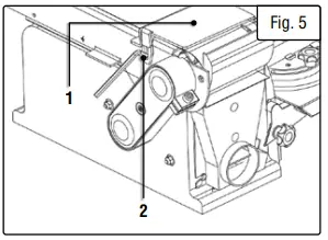
- MOUNTING THE WORK SUPPORT
- Align the work support (Fig. 5 – 1) with the hole.
- Install a lock washer and a flat washer on the hex screw.
- Insert the hex screw into the work support hole and tighten (Fig. 5 – 2).
- Adjust the work support height to avoid contact with the sanding belt.
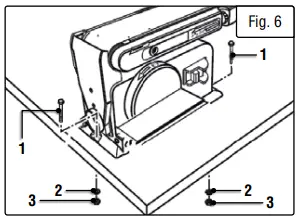
- MOUNTING THE SANDER TO A WORKBENCH
WARNING! If during operation there is any tendency for the sander to tip over, slide or walk on the supporting surface, the sander should be properly mounted to a workbench or stand.- Position the sander on the workbench where it will be used.
- Mark the workbench through the mounting holes located in the sander base. Drill holes in the workbench at the marks.
- Using mounting bolts (Fig. 6 – 1), lock washers (Fig. 6 – 2), and hex nuts (Fig. 6 – 3) (not supplied), secure the sander to the workbench.

NOTE: All bolts should be inserted from the top. Washers and hex nuts should be fastened from the underside of the work-bench (Fig. 6).
- INSTALLING THE SANDING BELT
- Loosen the bed locking screw with the hex key. Raise the sanding bed about 45°; tighten the bed locking screw (Fig. 7 – 1).
- Pull the tension lever, releasing the tension.
- Locate the directional arrow (Fig. 7 – 2) on the smooth side of the sanding belt (Fig. 7 – 3).
- Place the sanding belt over the drums (Fig. 7 – 4) with the directional arrow pointing towards the dust chute.
- Center the belt correctly on both drums.
- Push the tension lever back to tighten the belt to the bed.
- Loosen the bed locking screw; lower the bed to a horizontal position. Tighten the bed locking screw.
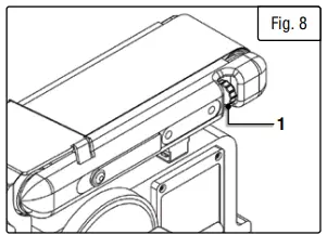
- SANDING BELT TRACKING ADJUSTMENT
- Plug in the power cord.
- Turn the switch ON and OFF to make sure the sanding belt is correctly centered and not sliding off the idler and drive roller drums.
- If the sanding belt moves toward the disc, slightly turn the tracking knob (Fig. 8 – 1) counterclockwise.
- If the sanding belt moves away from the disc, slightly turn the tracking knob clockwise.
- . Turn the switch ON and OFF again; readjust the tracking knob if necessary.
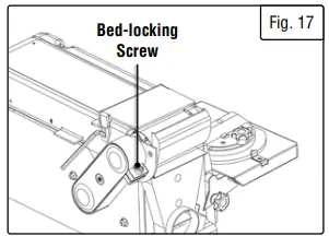
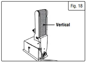
- CHANGE SANDING BELT BED POSITION (FIG. 17)
The sanding bed can be used in the horizontal or vertical posi-tions or any angle in between. To use in the vertical position, do the following:- Loosen the bed locking screw with hex key, move the bed to the desired vertical position.
- Tighten the locking screw when at desired position.
- DUST PORT OPERATION
- The dust port can be easily connected to a large diameter shop vacuum hose.
- Sanding operations are inherently dusty. To help minimize the amount of dust that escapes into the surrounding air, this sander is equipped with a 2-1/4” dust chute that can be easily connected to a dust-collection system. It is strongly recommended that users employ a dust-collection system when using this belt & disc sander.
- Use of a mask or respirator is still recommended even when a dust-collection system is in use.
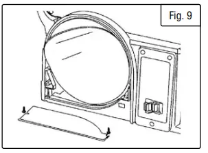
- INSTALL A NEW SANDING DISC (FIG. 9)

- Remove the two screws from the sanding disc guard and remove the guard.
- Remove the used sanding disc. A heat gun may come in handy to remove old discs. Your friends at WEN offer several models, available for purchase at wenproducts.com.
- Wipe the sanding disc plate clean.
- Peel the backing from the new sanding disc, align the disc with the plate and press the sanding disc firmly on to the plate.
- Reinstall the disc guard and tighten the screws.
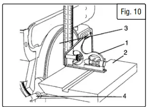
- SQUARING THE TABLE
To ensure accurate end sanding, the work table (Fig. 10 – 2) must be square to the sanding surfaces prior to using the tables for disc sanding.
- Adjust the table to be 90° with the sanding surface.
- Using a combination square (Fig. 10 – 1), place one end on the table with the ruler end against the sanding surface (Fig. 10
- Check that the table is 90° to the sanding surface.
- If the table is not 90° to the sanding surface, loosen the han-dle (Fig. 10 – 4), adjust the table, tighten the handle and recheck with the square.
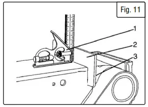
- SQUARE THE WORK SUPPORT
The work support (Fig. 11 – 2) must be square to the sanding belt when using the belt sander in a horizontal position. To keep the workpiece from being carried along the belt:
- Make sure the sanding belt is tight; also check that the ten-sion lever is fully tightened.
- Place the combination square (Fig. 11 – 1) on the belt with the ruler against the work support (Fig. 11 – 2).
- Adjust by loosening the work support locking screw (Fig. 11
- square the work support.
- Tighten the work support locking screw (Fig. 11 – 3).
OPERATION
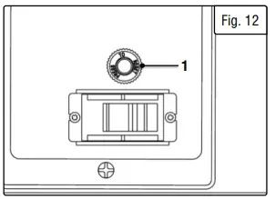
CIRCUIT BREAKER
To protect the motor, your sander is equipped with a circuit breaker (Fig. 12 – 1), located on the right side of the unit near the power switch. If the motor is overloaded, the circuit breaker will trip. To reset the breaker, wait a moment and then press it in to reset it. Do not press too hard on the sandpaper, or the motor may overload.
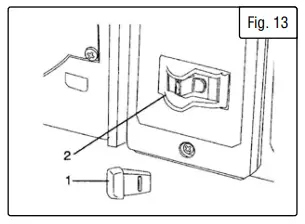
- ON / OFF SWITCH
The keyed switch is intended to prevent unauthorized use of the sander.
WARNING! Remove the safety key whenever the sander is not in use. Place the key in a safe place and out of the reach of children.- To turn sander ON, insert the safety key (Fig. 13 – 1) into the key slot (Fig. 13 – 2) in the center of the switch.
- Push key firmly into the slot, then push switch to the ON posi-tion to start the sander.
- To turn the sander OFF push switch to the OFF position.
- Remove the safety key when the sander has come to a com-plete stop by gently pulling it forward and out.

- SURFACE SANDING ON SANDING BELT
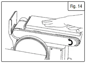
Hold the workpiece firmly with both hands. Keep fingers away from sanding belt. Keep the workpiece end against the backstop and move it slowly across the sanding belt. Apply enough pres-sure to remove material; excessive pressure will reduce sanding efficiency and may stall the motor (Fig. 14). - SANDING INSIDE CURVES
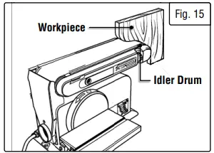
When sanding inside-curves on the belt-sander, always sand on the idler drum end of the work support station (right side of the machine as shown in diagram). Hold the workpiece firmly, keep-ing fingers away from the sanding belt. Keep the curve pressed firmly against the idler drum, moving the work evenly back and forth across the drum (Fig. 15).
NOTE: Use extra caution when sanding very thin pieces, and apply only enough pressure to allow the sanding belt to remove the material. - END SANDING & OUTSIDE CURVE SANDING
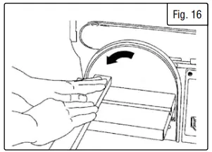
Use the sanding disc sanding the ends of small and narrow workpieces and outside curved edges. Always work on the left side of the disc (downward rotation side), holding the workpiece firmly with light pressure against the sanding disc (Fig. 16).
CAUTION! To avoid personal injury and/or damage to the workpiece, become familiar with the rotation of the belt and disc sanding surfaces.
The belt sander rotates counterclockwise or downward toward the table or backstop. The disc sander rotates counterclockwise, downward toward the table on the left side of the disc and up-ward from the table on the right side of the disc. Always use the left side of the disc; using the right side of the disc will cause the workpiece to fly up or kickback and could result in injury. Re-view this instruction manual for correct operation, adjustments, and basic sanding operations. - ELT SANDER – HORIZONTAL & VERTICAL SANDING
Your belt & disc sander can sand vertically as well as horizon-tally. Depending on the operator’s needs and the workpiece, the work-support can be used with either the horizontal or vertical position.
To change from one position to the other:- Locate the 6mm hex wrench.
- Loosen the bed-locking screw by turning it counter-clock-wise.
- Manually move the work support station into the vertical or horizontal position, as required.
- Retighten the bed-locking screw by turning it clockwise (using the 6mm hex wrench).
NOTE: Sand long workpieces with the sanding belt in the vertical position by moving the work evenly across the sanding belt.
- MITER GAUGE – DISC SANDER
A miter gauge is supplied with your sander, and can be used on the disc table. The miter gauge head can be set anywhere up to 60º (right or left) by loosening the lock-knob, setting the miter gauge head to the desired angle, and retightening the lock-knob. - SANDING SMALL END GRAIN & OTHER SMALL SURFACES USING MITER GAUGE
Use of the miter gauge is recommended for sanding small end surfaces on the sanding disc.
NOTE: Always move the workpiece across the sanding disc from the left side towards the right side, and be sure to hold the workpiece down tightly onto the table surface. - MOVING THE WORK TABLE FROM DISK TO BELT
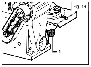
- Remove the work table by removing the orange lock knob (Fig. 19 – 1) from under the table.

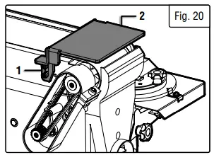
- Remove the two 6mm socket head cap screws (Fig. 20 – 1) holding the work stop (Fig. 20 – 2) from on top of the sanding belt.
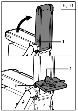
- Raise the sanding belt to the vertical position (Fig. 21).
- Attach the work table (Fig. 21 – 2) to the belt support using the lock knob (Fig. 21 – 3).


- Remove the work table by removing the orange lock knob (Fig. 19 – 1) from under the table.
MAINTENANCE
WARNING! For your own safety, turn the switch OFF and remove the plug from the electrical outlet before adjusting or performing maintenance or lubrication work on the belt / disc sander.
Before using, check to make sure parts are not damaged, missing, or worn. Check for alignment of moving parts, binding of moving parts, improper mounting, or any other conditions that may affect the sander operation. If any of these conditions ex-ist, do not use the sander until parts are replaced or the sander is properly repaired. Frequently blow or vacuum dust from all sanding parts and motor housing.
WARNING! Any attempt to repair or replace electrical parts on this tool may be hazardous. Repairs should be done by a qualified service technician.
LUBRICATION
Ball bearings are grease packed at the factory and require no further lubrication. Use a spray lubricant on all moving table parts to ensure smooth operation.
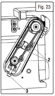
ADJUST THE DRIVE BELT (FIGS. 22 & 23)
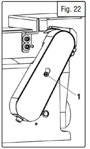
- Loosen the screw (1) securing the drive belt housing cover to the drive belt hous-ing. Lift the cover up and over the screw and remove it.
- Using a Phillips screwdriver (not included), loosen the 3 screws (2) securing the drive belt housing to the sander body.
- Using the included hex wrench, loosen (turn counterclockwise) the hex screw (3) at the bottom of the drive belt housing. This will release the tension on the drive belt and allow you to perform adjustments or install a new drive belt.
- Re-seat the belt on the pulleys, making sure the belt is properly seated in the grooves of both pulleys.
- Re-tighten the belt by tightening (turning clockwise) the hex screw at the bottom of the drive belt housing.
- Tighten all 3 screws (2).
- Test belt tension by squeezing both sides of the belt. If properly adjusted, the belt should “give” between 1/8–1/4 inch (3–6 mm). Make sure that the belt grooves are properly seated in the pulleys.
- Carefully reinstall the drive belt housing cover. Tighten the screw.
NOTE: Excessive tightness on the pulley belt will cause increased noise and motor overload. Premature failure will occur if belt is too loose.
TROUBLESHOOTING GUIDE
WARNING! Stop using the generator immediately if any of the following problems occur or risk serious personal injury. If you have any questions, please contact customer service at 1-800-232-1195 (M-F 8-5 CST), or email [email protected].
| Problem | Cause | Solution |
| Sanding grains easily rub off belts or discs. | Sanding belt/disc has been stored in the wrong environment. | Store sanding accessories away from extremely hot or dry environ- ments. |
| Sanding belt/disc has been dam- aged or folded. | Store sanding accessories flat – not bent or folded. | |
|
Deep sanding grooves or scars in workpiece. | Sanding belt/disc is too coarse for the desired finish. | Use a finer-grit sanding accessory. |
| Workpiece sanded across the grain. | Sand with the wood grain. | |
| Too much force applied to work- piece. | Reduce pressure on workpiece while sanding. Let the tool do the work. | |
| Workpiece held still against belt/ disc for too long. | Keep workpiece moving while sand- ing. | |
|
Sanding surface clogs quickly. | Too much force applied to work- piece. | Reduce pressure on workpiece while sanding. Let the tool do the work. |
| Sanding softwood (or highly resin- ous species). | Use different stock/sanding ac- cessories, or accept that this will happen, and plan on cleaning or replacing belts/discs frequently. | |
|
Workpiece’s surface is burnt. | Sanding belt/disc is too fine. | Use a coarser-grit sanding acces- sory. |
| Too much force applied to work- piece. | Reduce pressure on workpiece while sanding. Let the tool do the work. | |
| Workpiece held still against belt/ disc for too long. | Keep workpiece moving while sand- ing. | |
|
Motor will not start – no noise at all. | Unit not plugged in. | Plug unit into power source. |
| Incorrect size/length of extension cord. | Choose the proper size and length of extension cord; see p. 7. | |
| Power line breaker is tripped. | Ensure breaker is not tripped; reset breaker if necessary. | |
| Unit’s onboard breaker is tripped. | Push button to reset breaker. | |
| Defective power switch, relay, or motor. | Contact customer service at 1-800-232-1195. |
| Problem | Cause | Solution |
| Motor will not start – humming noise. | Excessive drive belt tension. | Reduce drive belt tension. |
| Defective motor bearing, capacitor, relay, or motor. | Contact customer service at 1-800- 232-1195. | |
|
Motor overheats. | Motor overloaded. | Reduce pressure on workpiece while sanding. Let the tool do the work. |
| Incorrect size/length of extension cord. | Choose the proper size and length of extension cord. | |
| Not using dust collection, or work- ing in a hot environment | Always use dust collection. Remove dust from tool housing. Try to move to a cooler environment. | |
| Motor stalls when load applied to belt/disc. | Too much force applied to work- piece. | Reduce pressure on workpiece while sanding. Let the tool do the work. |
| Incorrect size/length of extension cord. | Choose the proper size and length of extension cord. | |
|
Excessive vibration. | Incorrect sanding belt tension. | Adjust sanding belt tension. |
| Loose drive belt. | Increase drive belt tension. | |
| Weak or broken tension spring. | Call customer service at 1-800-232- 1195. | |
| Idler drum is too loose. | Call customer service at 1-800-232- 1195. | |
| Defective bearing or motor. | Call customer service at 1-800-232- 1195. | |
| Sanding belt stops when workpiece is applied to belt. | Insufficient drive belt tension. | Increase drive belt tension. |
| Insufficient sanding belt tension. | Adjust sanding belt tension. | |
|
Noisy operation. | Loose fastener. | Turn tool OFF & unplug it. Check machine for loose fasteners. |
| Loose drive belt. | Increase drive belt tension. | |
| Defective bearing. | Contact customer service at 1-800- 232-1195. |
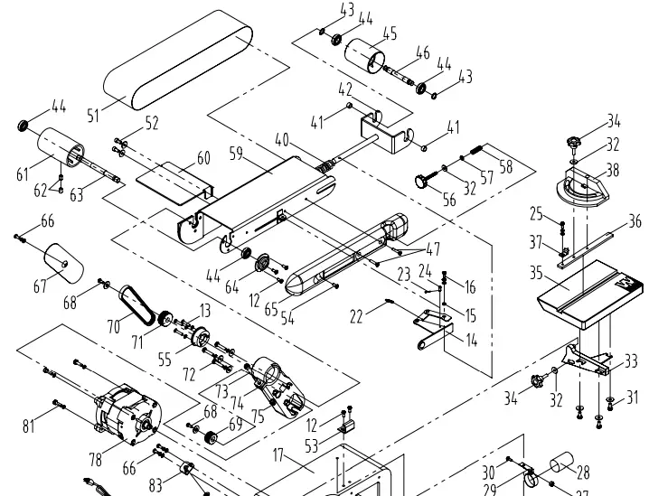
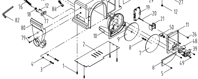
EXPLODED VIEW & PARTS LIST
| No. | Part No. | New Description | Qty |
| 1 | 90228-001 | Screw M4X6 | 4 |
| 2 | 90228-003 | Base Cover | 1 |
| 3 | 90228-012 | Screw M4X8 | 2 |
| 4 | 90228-015 | Lock Washer (4) | 2 |
| 5 | 90228-004 | Self-Tapping Screw ST4.2X10 | 2 |
| 6 | 90228-006 | Disc Cover | 1 |
| 7 | 90228-007 | Disc Paper | 1 |
| 8 | 90228-008 | Inner Hex Screw M6X16 | 1 |
| 9 | 90228-010 | Disc | 1 |
| 10 | 90228-011 | Disc Guard | 1 |
| 11 | 90228-022 | Switch Box | 1 |
| 12 | 90228-012 | Screw M5X8 | 8 |
| 13 | 90228-062 | Screw Assembly M5X25 | 3 |
| 14 | 6502-051 | Belt Tension Lever | 1 |
| 15 | 6502-048 | Bushing | 1 |
| 16 | 6502-016 | Screw Assembly M5X16 | 1 |
| 17 | 90228-017 | Base | 1 |
| 18 | 6502B-118 | Power Cord Clip 6P4 | 1 |
| 19 | 90228-022 | Switch Box Cover | 1 |
| 20 | 90228-020 | Screw ST2.9X30 | 1 |
| 21 | 90228-021 | Relay | 1 |
| 22 | 6502-050 | Spring | 1 |
| 23 | 6502-039 | Cotter Pin | 1 |
| 24 | 6502-016 | Pin 5×10 | 1 |
| 25 | 6502B-125 | Screw M4x8 | 1 |
| 26 | 6502B-126 | Screw M4X12 | 3 |
| 27 | 6502B-127 | Hex Nut M5 | 1 |
| 28 | 90228-028 | Capacitor | 1 |
| 29 | 90228-029 | Capacitor Support | 1 |
| 30 | 90228-047 | Screw M5x16 | 1 |
| 31 | 90228-031 | Hex Bolt Assembly M6X12 | 3 |
| 32 | 90228-032 | Big Flat Washer (6) | 3 |
| 33 | 90228-033 | Work Table Support | 1 |
| 34 | 90228-034 | Miter Gauge Knob | 1 |
| 35 | 90228-035 | Work Table | 1 |
| 36 | 6502-036 | Miter Gauge Bar | 1 |
| 37 | 6502-037 | Miter Gauge Pointer | 1 |
| 38 | 6502-038 | Miter Gauge | 1 |
| 39 | 90228-024 | Switch | 1 |
| 40 | 90228-037 | Tension Spring | 1 |
| 41 | 90228-038 | Bushing | 2 |
| 42 | 90228-039 | Belt Tension Support | 1 |
| 43 | 6502-043 | Retaining Ring D12 | 2 |
| No. | Part No. | New Description | Qty |
| 44 | 6502-044 | Bearing | 4 |
| 45 | 6502-045 | Idler Drum | 1 |
| 46 | 6502-046 | Idler Shaft | 1 |
| 47 | 6502B-147 | Screw M5x20 | 2 |
| 48 | 90228-077 | Switch Plate | 1 |
| 49 | 6502B-149 | ScrewST2.9×8 | 2 |
| 50 | 6502-091 | Circuit Breaker 8A | 1 |
| 51 | 90228-076 | Belt | 1 |
| 52 | 90228-080 | Inner Hex Screw Assembly M8X16 | 2 |
| 53 | 90228-075 | Belt Frame Support | 1 |
| 54 | 6502B-054 | Screw M5X16 | 1 |
| 55 | 6502-055 | Bearing Base | 1 |
| 56 | 90228-048 | Belt Tracking Knob | 1 |
| 57 | 90228-050 | Rubber Spring | 1 |
| 58 | 90228-051 | Belt Tracking Spring | 1 |
| 59 | 90228-052 | Belt Support | 1 |
| 60 | 90228-053 | Work Stop | 1 |
| 61 | 6502B-185 | Driving Drum & Shaft Assembly | 1 |
| 62 | 6502-062 | Inner Hex Screw M8X12 | 2 |
| 63 | 6502-063 | Driving Shaft | 1 |
| 64 | 90228-054 | Bearing Cap | 1 |
| 65 | 90228-055 | Belt Support Cover | 1 |
| 66 | 6502B-166 | Screw Assembly M5X12 | 3 |
| 67 | 6502B-167 | V-groove Belt Guard Cover | 1 |
| 68 | 90228-058 | Pulley Screw and Washer Assembly | 2 |
| 69 | 6502B-169 | Driving Pulley | 1 |
| 70 | 6502B-170 | V-groove Belt 155J | 1 |
| 71 | 6502B-171 | Driven Pulley | 1 |
| 72 | 90228-064 | Screw Assembly M6X25 | 3 |
| 73 | 90228-065 | Inner Hex Screw M8X25 | 1 |
| 74 | 90228-066 | V-groove Belt Guard | 1 |
| 75 | 90228-067 | Hex Nut M8 | 1 |
| 76 | 90228-072 | Power Cord | 1 |
| 77 | 6502B-077 | Power Cord Clip Plate | 1 |
| 78 | 6502B-178 | Motor Assembly | 1 |
| 79 | 90228-040 | Screw M5X20 | 2 |
| 80 | 90228-073 | Dust Collection Cover | 1 |
| 81 | 90228-046 | Hex Bolt Assembly M6X20 | 3 |
| 82 | 6502B-182 | Hex Wrench M6X90X32 | 1 |
| 83 | 6502B-183 | V-groove Belt Guard Support | 1 |
| 84 | 6502B-184 | Inner Hex Screw Assembly M8X30 | 1 |
EXPLODED VIEW & PARTS LIST
WARRANTY STATEMENT
WEN Products is committed to building tools that are dependable for years. Our warranties are consistent with this commitment and our dedication to quality.
LIMITED WARRANTY OF WEN PRODUCTS FOR HOME USE
- GREAT LAKES TECHNOLOGIES, LLC (“Seller”) warrants to the original purchaser only, that all WEN consumer power tools will be free from defects in material or workmanship during personal use for a period of two (2) years
used for professional or commercial use. Purchaser has 30 days from the date of purchase to report missing or damaged parts. - SELLER’S SOLE OBLIGATION AND YOUR EXCLUSIVE REMEDY under this Limited Warranty and, to the extent per-mitted by law, any warranty or condition implied by law, shall be the replacement of parts, without charge, which are defective in material or workmanship and which have not been subjected to misuse, alteration, careless handling, misrepair, abuse, neglect, normal wear and tear, improper maintenance, or other conditions adversely affecting the Product or the component of the Product, whether by accident or intentionally, by persons other than Seller. To make a claim under this Limited Warranty, you must make sure to keep a copy of your proof of purchase that clearly direct vendor of Great Lakes Technologies, LLC. Purchasing through third party vendors, including but not limited to garage sales, pawn shops, resale shops, or any other secondhand merchant, voids the warranty included with this product. Contact [email protected] or 1-800-232-1195 with the following information to make arrangements: your shipping address, phone number, serial number, required part numbers, and proof of purchase. Damaged or defective parts and products may need to be sent to WEN before the replacements can be shipped out.
- when we turning a product for warranty service, the shipping charges must be prepaid by the purchaser. The product must be shipped in its original container (or an equivalent), properly packed to withstand the hazards of shipment. The product must be fully insured with a copy of the proof of purchase enclosed. There must also be a description of the
will be returned and shipped back to the purchaser at no charge for addresses within the contiguous United States. - THIS LIMITED WARRANTY DOES NOT APPLY TO ITEMS THAT WEAR OUT FROM REGULAR USAGE OVER TIME, INCLUDING BELTS, BRUSHES, BLADES, BATTERIES, ETC. ANY IMPLIED WARRANTIES SHALL BE LIMITED IN DURATION TO TWO (2) YEARS FROM DATE OF PURCHASE. SOME STATES IN THE U.S. AND SOME CANADIAN PROVINCES DO NOT ALLOW LIMITATIONS ON HOW LONG AN IMPLIED WARRANTY LASTS, SO THE ABOVE LIMI-TATION MAY NOT APPLY TO YOU.
- IN NO EVENT SHALL SELLER BE LIABLE FOR ANY INCIDENTAL OR CONSEQUENTIAL DAMAGES (INCLUDING BUT NOT LIMITED TO LIABILITY FOR LOSS OF PROFITS) ARISING FROM THE SALE OR USE OF THIS PRODUCT. SOME STATES IN THE U.S. AND SOME CANADIAN PROVINCES DO NOT ALLOW THE EXCLUSION OR LIMITATION OF INCIDENTAL OR CONSEQUENTIAL DAMAGES, SO THE ABOVE LIMITATION OR EXCLUSION MAY NOT APPLY TO YOU.
- THIS LIMITED WARRANTY GIVES YOU SPECIFIC LEGAL RIGHTS, AND YOU MAY ALSO HAVE OTHER RIGHTS WHICH VARY FROM STATE TO STATE IN THE U.S., PROVINCE TO PROVINCE IN CANADA AND FROM COUNTRY TO COUNTRY.
- THIS LIMITED WARRANTY APPLIES ONLY TO ITEMS SOLD WITHIN THE UNITED STATES OF AMERICA, CANA-DA AND THE COMMONWEALTH OF PUERTO RICO. FOR WARRANTY COVERAGE WITHIN OTHER COUNTRIES, CONTACT THE WEN CUSTOMER SUPPORT LINE. FOR WARRANTY PARTS OR PRODUCTS REPAIRED UNDER WARRANTY SHIPPING TO ADDRESSES OUTSIDE OF THE CONTIGUOUS UNITED STATES, ADDITIONAL SHIPPING CHARGES MAY APPLY.


