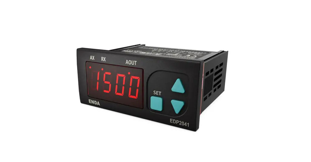
![]() EDP2041 Digital Potentiometer
EDP2041 Digital Potentiometer
User Guide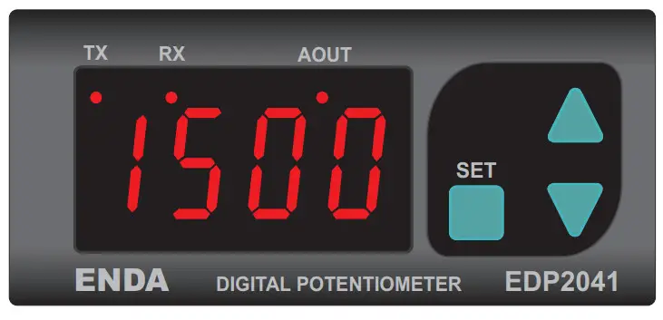

![]() Read this document carefully before using this device. The guarantee will be expired by damages if you don’t attend to the directions in the user manual. Also, we don’t accept any compensation for personal injury, material damage, or capital disadvantages.
Read this document carefully before using this device. The guarantee will be expired by damages if you don’t attend to the directions in the user manual. Also, we don’t accept any compensation for personal injury, material damage, or capital disadvantages.
Thank you for choosing ENDA EDP2041 potentiometer.
- 35x77mm sized.
- 4 digits display.
- Easy to use by front panel keypad.
- Communication via RS-485 Modbus protocol or synchronous running between two or more potentiometers (Optional).
- Preset value can be adjusted from external buttons.
- The display scale can be adjusted between -1999 and 9999.
- The decimal point can be adjusted between 1. and 3. digits.
- 0-10V,0-20 mA a, and 4-20mA output with adjustable minimum and maximum values.
- ‘Soft on and ‘soft off’ properties can be selected.
- Parameter access protection on 3 levels.
- CE marked according to European Norms.
Order Code: EDP2041 –![]()
- Supply Voltage UV….90-250V AC LV……10-30V DC /8-24V AC
- Modbus
RS… Modbus (Specify at Order)
TECHNICAL SPECIFICATIONS
| ENVIRONMENTAL CONDITIONS | ||
| Ambient/storage temperature | 0 … +50 °C/-25 … +70°C (without icing) | |
| Max. relative humidity | 80% Relative humidity for temperatures up to 31 % °C, decreasing linearly to 50% at 40°C. | |
| Rated pollution degree | According to EN 60529 | Front panel: IP65 Rear panel: IP20 |
| Height | Max. 2000m | |
![]() KEEP AWAY the device from exposure to corrosive, volatile, and flammable gases or liquids, and DO NOT USE the device in similar hazardous locations.
KEEP AWAY the device from exposure to corrosive, volatile, and flammable gases or liquids, and DO NOT USE the device in similar hazardous locations.
| ELECTRICAL CHARACTERISTICS | |
| Supply | 90-250 V AC 50/60Hz; 10-30V DC / 8-24V AC SMPS |
| Power consumption | Max. 7VA |
| Wiring | 2.5mm² Screw Connections |
| Date retention | EN 61326-1: 2013 (Performance criterion B for the EMC standards) |
| EMC | EEPROM (Min. 10 years) |
| Safety requirements | EN 61010-1: 2012 (pollution degree 2, overvoltage category II, measurement category I) |
| INPUTS | |
| Upwards input (UP) | Contact input or max. 24VDC logic input (active low) |
| Downwards input (DOWN) | Contact input or max. 24VDC logic input (active low) |
| OUTPUT | |
| 0-10V output | Accuracy :%0.1 Resolution : 1mV Fluctuation: Maximum 30mV Rise time from 0 to 10V is a maximum of 300ms Digitally adjusted maximum 10mA, max. 10V potentiometer output. |
| HOUSING | |
| Housing type | Suitable for flush-panel mounting according to DIN 43 700. |
| Dimensions | W77xH35xD71mm |
| Weight | Approx. 350g (after packing) |
| Enclosure material | Self-extinguishing plastics |
![]() Avoid any liquid contact while the device is switched on.
Avoid any liquid contact while the device is switched on.
DO NOT clean the device with solvent (thinner, gasoline, acid, etc.) and/or abrasive cleaning agents.
TERMS
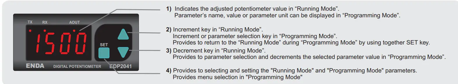
| ( 1 ) Digital display | 12,5 mm 4 digits 7 segment red LED display |
| ( 2 ),( 3 ),( 4 ) Keypad | Micro switch |
DIMENSIONS
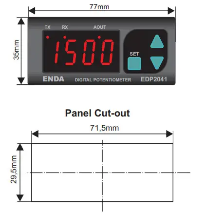
Depth
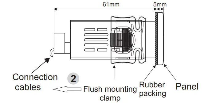
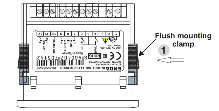
To remove the device from the panel :
- While pushing the flush-mounting clamp in that direction 1, pull out in the direction 2.
Note :
- Panel thickness should be
- There must be at least 60mm free space behind the device, otherwise, it would be difficult to remove it from the panel.
CONNECTION DIAGRAM
![]() ENDA EDP2041 is intended for installation in control panels. Make sure that the device is used only for the intended purpose. The electrical connections must be carried out by qualified staff and must be according to the relevant locally applicable regulations. During an installation, all of the cables that are connected to the device must be free of electrical power. The device must be protected against inadmissible humidity, vibrations, and severe soiling. Make sure that the operating temperature is not exceeded. The cables should not be close to the power cables or components.
ENDA EDP2041 is intended for installation in control panels. Make sure that the device is used only for the intended purpose. The electrical connections must be carried out by qualified staff and must be according to the relevant locally applicable regulations. During an installation, all of the cables that are connected to the device must be free of electrical power. The device must be protected against inadmissible humidity, vibrations, and severe soiling. Make sure that the operating temperature is not exceeded. The cables should not be close to the power cables or components.
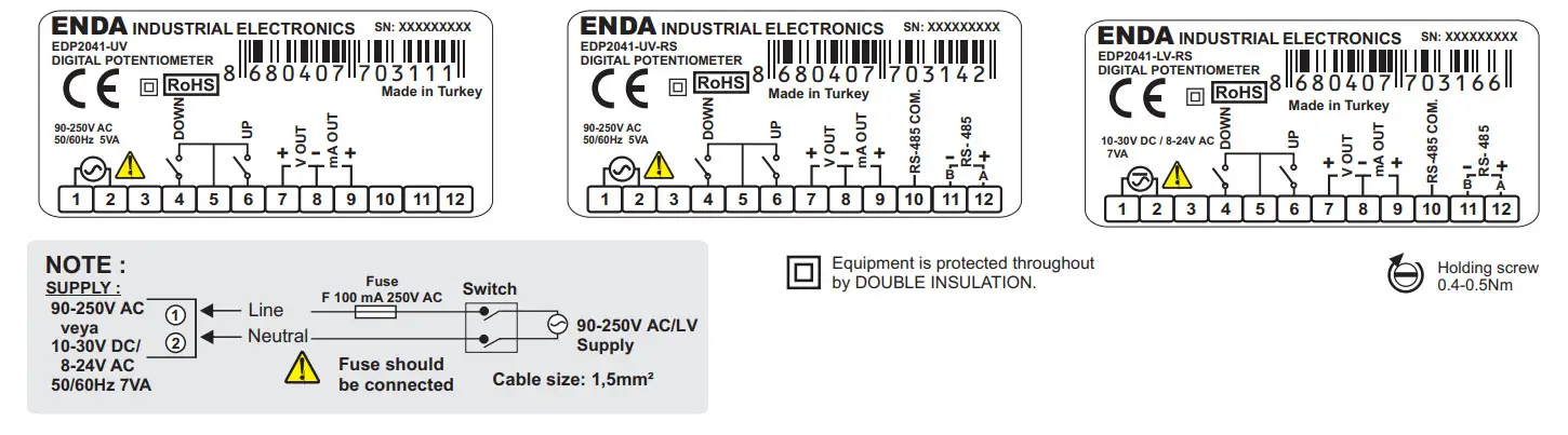
Note :
- Mains supply cords shall meet the requirements of IEC 60227 or IEC 60245.
- In accordance with the safety regulations, the power supply switch shall bring the identification of the relevant instrument and it should be easily accessible by the operator.
SYNCHRONIZED OPERATING CONNECTION
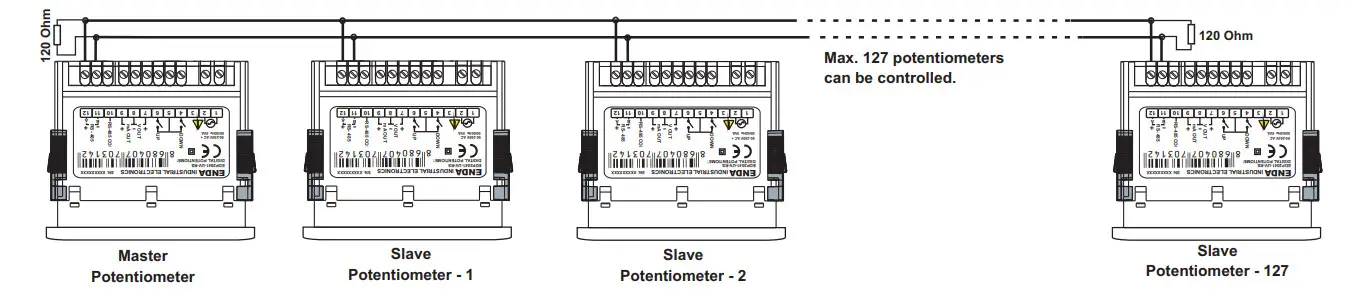
NOTE :
 the parameter should be selected C.Pot in the master potentiometer. In this case parameters of other potentiometers aren’t used. But be sure that
  isn’t selected in slave potentiometers to prevent confusion. Settings of slave potentiometers change proportional to the setting of the master potentiometer. For example; When Max. output of the master potentiometer is changed from 10V to 5V, max. the output of slave potentiometers decreases by half of the previous value proportional to this. If the previous output of the slave potentiometer is 6V, it decreases by 3V. P.on.c parameter of slave potentiometer should be selected oFF in order to understand the master potentiometer when a slave is energized.
- The computer should be used to change only a few potentiometers. In this case, there is no master potentiometer. The output of the required potentiometer is changed
according to. parameter.
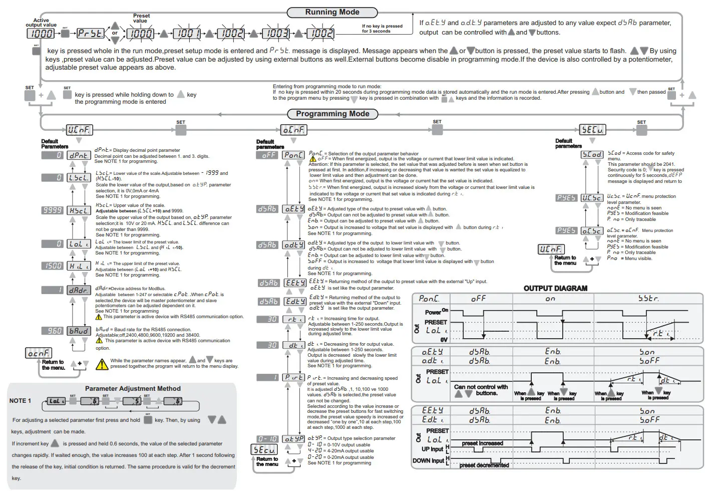
Running Mode
ENDA EDP2041 DIGITAL POTENTIOMETER MODBUS PROTOCOL ADDRESS MAP
Memory map for Holding Registers
| Parameter Number | Holding Register addresses Decimal (Hex) | Data Type | Data Content | Parameter Name | Read/Write Permission | Default Parameters |
| HO | 0000d (0000h) | Word | Percentage of the external control.Adjustable between %0.00 and %100.0 | Readable / Writable | 10000 | |
| H1 | 0001d (0001h) | Word | Preset value | Readable / Writable | 1000 | |
| H2 | 0002d (0002h) | Word | Decimal point | Readable / Writable | 0 | |
| H3 | 0003d (0003h) | Word | The lower value of the scale | Readable / Writable | 0 | |
| H4 | 0004d (0004h) | Word | The upper value of the scale | Readable / Writable | 9999 | |
| H5 | 0005d (0005h) | Word | The lower limit of the preset value | Readable / Writable | 0 | |
| H6 | 0006d (0006h) | Word | The upper limit of the preset value | Readable / Writable | 2000 | |
| H7 | 0007d (0007h) | Word | Device address for Rs485 network connection (Adjustable between 1-247.) If set to “0”,the control potentiometer mode is entered. | Readable / Writable | 1 | |
| H8 | 0008d( 0008h) | Word | Baud rate selection ( 0= None;1=2400bps ; 2=4800bps ; 3=9600bps ; 4=19200bps; 5=38400bps) | Readable / Writable | 3 | |
| H9 | 0009d (0009h) | Word | -(1)heofgr,oipenoinng,tr control parameter | Readable / Writable | 0 | |
| H10 | 0010d (000Ah) | Word | Output upper arrow button to fetch the value of the preset selection | Readable / Writable | 0 | |
| H11 | 0011d (000Bh) | Word | Output lower arrow button to fetch the value of the lower limit selection | Readable / Writable | 0 | |
| H12 | 0012d (000Ch) | Word | Time to increase the output voltage | Readable / Writable | 30 | |
| H13 | 0013d (000Dh) | Word | Time to decrease the output voltage | Readable / Writable | 30 | |
| H14 | 0014d (000Eh) | Word | Preset the value of the increment and decrement rate or cancel the setting 0 = cancel, | Readable / Writable | 1 | |
| H15 | 0015d (000Fh) | Word | Output type selection parameter 0 = 0-10y output, 1 = 4-20mA output ,2 = 0-20mA output | Readable / Writable | ||
| H16 | 0016d (0010h) | Word | User security parameter configuration menu (0 = Menu invisible, 1= Menu programmable, 2 or 3 = Menu only traceable). | Readable / Writable | 1 | |
| H17 | 0017d (0011h) | Word | Output security parameter configuration menu (0 = Menu invisible, 1= Menu programmable, 2 or 3 = Menu only traceable). | Readable / Writable | 1 | |
| H18 | 0018d (0012h) | Word | Function control parameter (23040d (5A00h) value is entered,any function executed. (23041d (5A01h) value is entered,the default values will be restored. | Readable / Writable | 0 | |
| H19 | 0019d (0010h) | Word | Returning method of the output to preset value with the external “Up” input. | Readable / Writable | 0 | |
| H2O | 0020d (0011h) | Word | Returning method of the output to preset value with the external “Down” input. | Readable / Writable | 0 |
The memory map for Coils
| Parameter Number | Input Register addresses Decimal (Hex) | Data Type | Data Content | Parameter Name | Read/Write Permission | Default Parameters |
| 10 | 0000d (0000h) | Word | Instant set value | Only readable | ||
| 11 | 0001d (0001h) | Word | % of the value the analog output (%0.00-°/0100.00 sensitivity) | Only readable |
The memory map for Discrete Input
| Parameter Number | Discrete input addresses | Data Type | Data Content | Parameter Name | Read/Write Permission Default | Parameters |
| DO | (0000)h | Bit | State of the external down button (0 = OFF .1 = ON) | Only readable | ||
| D1 | (0001)h | Bit | State of the external up button (0 = OFF .1 = ON) | Only readable |
MODBUS ERROR MESSAGES
Modbus protocol has two types of errors, communication errors, and operating errors. The reason of the communication error is data corruption in transmission. Parity and CRC control should be done to prevent communication errors. The receiver side checks the parity and CRC of the data. If they are wrong, the message will be ignored. If the format of the data is true but the function doesn’t perform for any reason, an operating error occurs. Slave realizes the error and sends an error message. The most significant bit of function is changed to ‘1’ to indicate an error in the error message by the slave. Error code is sent in the data section. Master realizes error type via this message.
Modbus Error Codes
| Error Code | Name | Meaning |
| 11 | ILLEGAL FUNCTION | The function code received in the query is not an allowable action for the slave. If a Poll Program Complete command was issued, this code indicates that no program function preceded it. |
| {2} | ILLEGAL DATA ADDRESS | The data address received in the query is not an allowable address for the slave. |
| {3} | ILLEGAL DATA VALUE | A value contained in the query data field is not an allowable value for the slave. |
Message example;
Structure of command message (Byte Format)
| Device Address | (0A)h | |
| Function Code | (01)h | |
| Beginning address of coils. | MSB | (04)h |
| LSB | (A1)h | |
| Number of coils (N) | MSB (00)h | |
| LSB | (01)h | |
| CRC DATA | LSB | (AC)h |
| MSB | (63)h | |
Structure of response message (Byte Format)
| Device Address | (0A)h | |
| Function Code | (81)h | |
| Error Code | (02)h | |
| CRC DATA | LSB | (BO)h |
| MSB | (53)h | |
As you see in the command message, coil information of (4A1)h = 1185 is required but there isn’t any coil with an 1185 address.
Therefore error code with the number (02) (Illegal Data Address) sends.
 SİSEL MÜHENDİSLİK ELEKTRONİK SAN. VE TİC. A.Ş.
Şerifali Mah.
Y.Dudullu 34775
Barbaros Cad. No:18
ÜMRANİYE/İSTANBUL-TURKEY
Tel : +90 216 499 46 64 Pbx. Fax : +90 216 365 74 01
url : www.enda.com.tr


