InCarTec 39-PGA-PDC Citroen and Peugeot CAN Steering Control Interface
Steering and PDC Interface
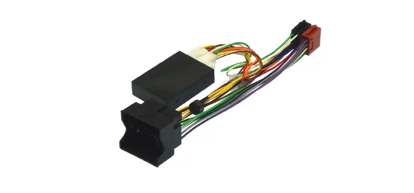
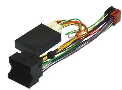
The 39-PGA-PDC is a CAN bus steering wheel control and PDC retention interface designed for use in Citroen and Peugeot cars. It allows for the retention of the original parking distance
control (PDC) system and enables the use of the steering wheel controls with an aftermarket radio. The interface generates various outputs, including CAN ignition and speed pulse, illumination, parking brake, and reverse gear signal outputs.
Patch Lead Setup
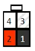
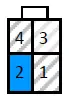
The patch lead connector has four pins and is used to connect the interface to an aftermarket radio. The pin configuration varies depending on the brand of the radio:
- Pioneer and Sony: Pin 1 black (base), Pin 2
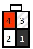
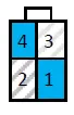
red (middle), Pin 3 not connected, Pin 4 white (tip) - Alpine, Clarion, and JVC: Pin 1 black (base),
Pin 2 white (tip), Pin 3 not connected, Pin 4 red (middle) - JVC, Kenwood, and Zenec: Pin 1 not connected,
Pin 2 blue (single wire), Pin 3 not connected, Pin 4 not connected - Chinese/Learning: Pin 1 not connected, Pin 2
blue (single wire), Pin 3 not connected, Pin 4 blue (single wire)
Note that the diagrams above show the connector viewed from the wire entry side.
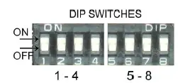
Switch Setup
The switches on the interface must be set according to the brand of radio and vehicle model. There are five switches in total; switches 1-4 relate to the brand of head unit, and switch 5 relates to the car model. The following table shows the switch settings for each brand:
| Switch 1 | Switch 2 | Switch 3 | Switch 4 | Brand |
|---|---|---|---|---|
| Off | On | Off | Off | Alpine |
| On | On | Off | Off | Kenwood |
| Off | Off | On | Off | JVC |
| Off | On | On | Off | Clarion |
| Off | Off | Off | On | Zenec |
| On | Off | On | On | Sony |
| Off | On | On | On | Pioneer |
| On | Off | Off | On | Chinese/Learning |
The settings for switch 5 depend on the car model and should be set to “Off On Off Off” for all models with PDC retention enabled.
Product Usage Instructions
- Connect the patch lead to the aftermarket radio, following the pin configuration for the brand of radio.
- Set the switches on the interface according to the brand of radio and car model, using the table above as a guide.
- Connect the interface to the car’s CANbus system.
- When connected, the green light on the interface should indicate that it recognizes the vehicle’s CANbus system, and the yellow light should indicate that it is providing an ignition power supply. If the green light is not on, check the CANbus connections and switch settings.
- To use the steering wheel controls with the aftermarket radio, follow these additional instructions:
- Press SRC and then >> to navigate menus. Press SRC to act as the OK button, and >> + Mode to go back.
39-PGA-PDC
Citroen and Peugeot CAN steering and PDC interface
CANbus steering wheel control and PDC retention interface for Citroen and Peugeot cars.The CANbus interface also generates CAN ignition and speed pulse, illumination, parking brake and reverse gear signal outputs.
Set up the patch lead
 Pioneer and Sony
- Pin 1 black (base)
- Pin 2 red (middle)
- Pin 3 not connected
- Pin 4 white (tip)
 Alpine, Clarion and JVC
- Pin 1 black (base)
- Pin 2 white (tip)
- Pin 3 not connected
- Pin 4 red (middle)
 JVC, Kenwood and Zenec
- Pin 1 not connected
- Pin 2 blue (single wire)
- Pin 3 not connected
- Pin 4 not connected
 Chinese/Learning
- Pin 1 not connected
- Pin 2 blue (single wire)
- Pin 3 not connected
- Pin 4 blue (single wire)
The 4 pin patch lead connector diagrams above are viewed from the wire entry side of the connector.
Set the switches
The switches on the interface need to be set according to the brand of radio and vehicle model. Open the black box and set the switches.
See the tables below for the switch settings. Switches 1-4 relate to the brand of head unit and switched 5-8 relate to the model of car.
| Switch | 5 | 6 | 7 | 8 |
| All models, PDC retention on | Off | On | Off | Off |
| Switch | 1 | 2 | 3 | 4 |
| Alpine | Off | On | Off | Off |
| Kenwood | On | On | Off | Off |
| JVC | Off | Off | On | Off |
| Clarion | Off | On | On | Off |
| Zenec | Off | Off | Off | On |
| Sony | On | Off | On | On |
| Pioneer | Off | On | On | On |
| Chinese/learning | On | Off | Off | On |
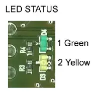
Green—CAN active
Yellow– Ignition output active
When connected the green light will indicate that the interface is recognizing the vehicles CANbus, and the yellow light will indicate the interface is giving out an ignition power supply.
If the green light is not on check the CANbus connections and switch settings.
Additional steering control functions
- SRC + >> “Mode” button of original radio
- SRC + << “Dark” button of original radio
- >> + << “Menu” button of original radio
Push and hold for 3+ seconds
Menu button.
This will allow you to access the menu settings, the steering wheel buttons (Vol+, Vol-, << and >>) will now navigate the menus. SRC button will act as the OK button and >> + << together will act as the ESC button.
NOTE: The parking buzzer does not give an initial tone to signify that reverse gear has been selected. Test the reversing tones by reversing the car towards an object, the reverse tones will not always sound if the ignition is on and the engine is not running.
Loose bullet connections
- Blue— Electric/Amplified antenna phantom power (where required)
- Blue/White— amplifier turn on
- Brown— Mute


