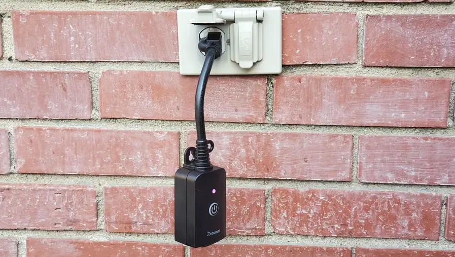
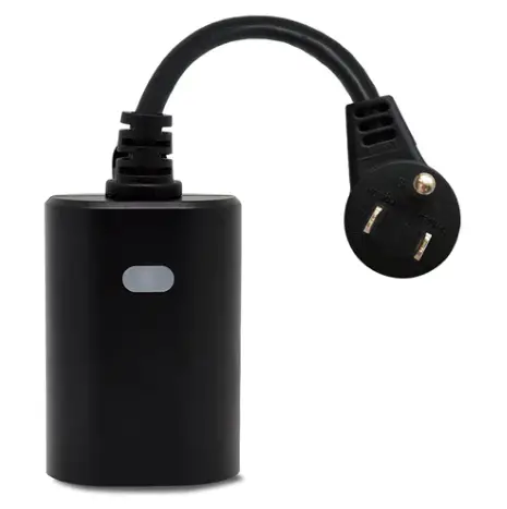
AeoTec ZWA042-A Outdoor Smart Plug
Engineering Specifications
This product can be operated in any Z-Wave™ network with other Z-Wave Plus™ certified devices from other manufacturers. All non-battery operated nodes within the network will act as repeaters regardless of vendor to increase reliability of the network. Each module is designed to act as a repeater, which will re-transmit a radio frequency (RF) signal by routing the signal around obstacles and radio dead spots to ensure that the signal is received at its intended destination. ZWA042-A is a security enabled Z-Wave Plus device. A security Enabled Z-Wave Plus Controller must be used in order to fully utilize the product.
Library and Command Classes
Embedded SDK
- v 7.16
Device Type
- ROOT device type
Generic Type: GENERIC_TYPE_SWITCH_BINARY(0x10) Specific Type: SPECIFIC_TYPE_NOT_USED(0x00) - Endpoint #1 type
GENERIC_TYPE: GENERIC_TYPE_SWITCH_BINARY(0x10) SPECIFIC_TYPE: SPECIFIC_TYPE_NOT_USED(0x00) - Endpoint #2 type
GENERIC_TYPE: GENERIC_TYPE_SWITCH_MULTILEVEL(0x11) SPECIFIC_TYPE: SPECIFIC_TYPE_COLOR_TUNABLE_MULTILEVEL(0x02)
Role Type
Always On Slave (AOS): ROLE_TYPE_SLAVE_ALWAYS_ON (0x05)
Command Class
ROOT CC List
| Command Class Name | Version | Required Security Class |
| Z-Wave Plus Info | V2 | none |
| Security 2 | V1 | none |
| Supervision | V1 | none |
| Transport Service | V2 | none |
| Association | V2 | highest granted |
| Association Group Information | V3 | highest granted |
| Multi-Channel Association | V3 | highest granted |
| Version | V3 | highest granted |
| Manufacturer Specific | V2 | highest granted |
| Device Reset Locally | V1 | highest granted |
| Power Level | V1 | highest granted |
| Indicator | V3 | highest granted |
| Firmware Update Meta Data | V5 | highest granted |
| Configuration | V4 | highest granted |
| Notification | V8 | highest granted |
| Multi-Channel | V4 | highest granted |
| Switch Binary | V2 | highest granted |
| Clock | V1 | highest granted |
| Scene Activation | V1 | highest granted |
| Scene Actuator Configuration | V1 | highest granted |
Endpoint #1 CC List
| Command Class Name | Version | Required Security Class |
| Z-Wave Plus Info | V2 | none |
| Security 2 | V1 | none |
| Supervision | V1 | none |
| Association | V2 | highest granted |
| Association Group Information | V3 | highest granted |
| Multi-Channel Association | V3 | highest granted |
| Switch Binary | V2 | highest granted |
| Scene Activation | V1 | highest granted |
| Scene Actuator Configuration | V1 | highest granted |
| Notification | V8 | highest granted |
Endpoint #2 CC List
| Command Class Name | Version | Required Security Class |
| Z-Wave Plus Info | V2 | none |
| Security 2 | V1 | none |
| Supervision | V1 | none |
| Association | V2 | highest granted |
| Association Group Information | V3 | highest granted |
| Multi-Channel Association | V3 | highest granted |
| Color Switch | V3 | highest granted |
| Switch Multilevel | V4 | highest granted |
Familiarize yourself with your Outdoor Plug
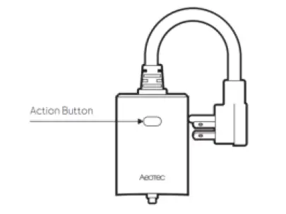
Z-Wave Network Operation
| Functions | Action Button | Description | |
| Inclusion | 1x tap | Out of network | Send NIF for network pairing/ inclusion (yellow LED remains solid state). If pairing is successful, the LED will flash white/green for 2s, then deactivates. |
| In network | Controls/ toggles output ON/OFF | ||
| Exclusion | 2x tap | In network | Send NIF for network unpairing/ exclusion (purple LED keeps ON for 2s and then OFF). |
| Out of network | N/A | ||
| Nothing | Press and hold for 1 – 5s | N/A. | |
| Entering RF power level test mode | Press and hold for 5 – 9s | Cyan led will remain solid, then release the button, the Plug starts power level testing. The led will be light up with 1 of 3 colors for 2 seconds after the diagnosing is complete. (Red = bad, Yellow = ok, Green = Good) | |
| Nothing | Press and hold for 9 – 15s | N/A. Red Led remains solid on. |
| Nothing | Press and hold for 15-20s | N/A. Red Led will blink. |
|
Factory reset |
Press and hold for more than 20s | Blue LED will blink, it starts the factory reset process, then return to factory reset LED status.
Note: Please use this procedure only when the network primary controller is missing or otherwise inoperable. |
Association Groups
The device supports 1 association group that supports max 5 associated nodes.
Group 1 is Lifeline group, all nodes associated in this group will receive the messages sent by device through Lifeline.
The Command Class supported by each association group is shown in the table below:
ROOT device:
| ID | Name | Node Count | Profile | Function |
| 1 | Lifeline | 5 | General: Lifeline | Device Reset Locally Notification: Issued when Factory Reset is performed. Indicator Report: Issued when included successfully. Switch Binary Report: Issued when output status is changed. Basic Report: Issued when output status is changed. Multilevel Switch Report: Issued LED brightness report. Color Switch Report Issued LED color report. |
Endpoint #1:
| ID | Name | Node Count | Profile | Function |
| 1 | Lifeline | 0 | General: Lifeline | Switch Binary Report |
l Endpoint #2:
| ID | Name | Node Count | Profile | Function |
| 1 | Lifeline | 0 | General: Lifeline | Multilevel Switch Report Color Switch Report |
Basic Command Map
- Basic CC is mapped to Switch Binary Command Class.
- Basic Set is mapped to Switch Binary Set.
Indicator Command Class
| Indicator ID | Property ID |
| 0x50 (NODE IDENTIFY) | 0x03(ON OFF PERIOD) |
| 0x50 (NODE IDENTIFY) | 0x04(ON OFF CYCLES) |
| 0x50 (NODE IDENTIFY) | 0x05(ONE TIME ON OFF PERIOD) |
Manufacturer Information
| Parameter | Value |
| Manufacturer ID 1 | 0x03 |
| Manufacturer ID 2 | 0x71 |
| Product Type ID 1 | 0x01 |
| Product Type ID 2 | 0x03 |
| Product ID 1 | 0x00 |
| Product ID 2 | 0x2A |
Configuration
User can change the default settings by the below configuration parameters. After device reset, all these parameters will be set to their default values.
| Parameter Number | Name | Information | Size | MIN | MAX | Default | Description |
| 1 | Change LED light setting | Setting to change the reaction of LED setting | 1 | 0 | 2 | 2 | 0- Disable LED completely 1- Turn on between particular times only (Night Light Mode) 2- Display ON/OFF status 3- Display the reverse state of ON/OFF status 4- Display always ON state. |
| 2 | Night Light Mode | Night Light ON time | 4 | 0 | 4294967 295 | 1572864 (18:00) | 0xRRHHMMSS: RR= reserved HH =Hours MM = Minutes SS = Seconds |
| Default= 0x00180000 (18:00) | |||||||
| 3 | Night Light Mode | Night Light OFF time | 4 | 0 | 4294967 295 | 393216 (6:00) | 0xRRHHMMSS: RR= reserved HH =Hours MM = Minutes SS = Seconds |
| Default= 0x00060000 (6:00) |
| 4 | Flash/Strobe LED light | Set the Duration / Play | 1 | 0 | 255 | 0 | 0- indicates that it is not blinking 1-255 set the duration and start the blinking process |
| 5 | Flash/Strobe LED light | Set the amount of blinks per second | 1 | 1 | 24 | 5 | 1-24 blink times per second |
| 7 | Action Button control the Plug | Plug always on – prevents the plug from being turned off via its button | 1 | 0 | 2 | 1- 0 | 0- the plug will operate as normal and can be turned on or off 1- the button on smart plug will be disabled for on and off commands, but still work for network removal or inclusion 2- the plug will ignore any commands to turn it off AND it’ll ignore any use of the button (but the button will still work for network removal or inclusion) |
| 8 | Power Restore | Status after power failure. | 1 | 0 | 2 | 2 | 0- returns to last known state when repowered 1- return to ON 2- return to OFF |
| 30 | Alarm settings | Determines if alarms are enabled in Switch, and what Switch will react to which alarms. | 1 | 0 | 128 | 0 | 0 – Disable all alarm settings 1 – smoke alarm 2 – CO alarm 4- CO2 alarm 8 – Heat alarm 16 – Water alarm 32 – Access Control (DW Sensor open) 64 – Home Security (intrusion) 128 – Motion Sensor trigger |
| 31 | Alarm Response in Device | Enabled by (Alarm settings), and determines what the switch does in the case an alarm is triggered | 1 | 0 | 3 | 0 | 0 – disable, no reaction to alarm settings 1 – Switch is ON 2 – Switch if OFF 3 – 255: Sets rate at which Switch turns ON and OFF in seconds (ie. if set to 3, then switch will turn ON in 0.3 seconds, and then turn OFF in 0.3 seconds in a cycle until user disables the alarm manually, if set to 255, then it will cycle every 25.5 seconds). |
| 32 | Setting to disable alarm | Determines the method of disabling the alarm of the device | 1 | 0 | 255 | 1 | 0 – Can be disabled by 1x tapping switches action button once 1 – Can be disabled by 2x tapping Switches action button within 1 second. 2 – Can be disabled by 4x tapping Switches action button within 2 seconds 3 – Can be disabled by pressing and holding Switches action button for 10 seconds. 4 – Can be disabled by Z-Wave commands. (State idle 0x00 event) 5 – 255: Sets the duration of the alarm in seconds (ie. Customer sets this setting to 50, the alarm state of the Switch will disable after 50 seconds) |
| 40 | Auto Turn Off Timer | Timer that auto turn off once turned on. | 4 | 0 | 86400 | 0 | 0- disabled 1 – 86400 Auto turn off after 1-86400s once |
| turned on | |||||||
| 41 | Auto Turn On Timer | Timer that auto turn on once turned off. | 4 | 0 | 86400 | 0 | 0- disabled 1 – 86400 Auto turn on after 1-86400s once turned off |
Security Network
This device is a security enabled Z-Wave Plus product that is able to use encrypted Z-Wave Plus messages to communicate to other security enabled Z-Wave Plus products.
The device supports the security function with S2 encrypted communication. The device will auto switch to the security mode when the device included with a security controller. In the security mode, the commands will use security command class wrapped to communicate with others, otherwise the device will not response any commands.
This device supports security levels are listed in below table:
SmartStart
SmartStart enabled products can be added into a Z-Wave network by scanning the Z-Wave QR Code present on the product with a controller providing SmartStart inclusion. No further action is required and the SmartStart product will be added automatically within 10 minutes of being switched on in the network vicinity. You can find the QR code on the bottom of the product, like this: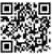
And the DSK information will be shown like this:
DSK: XXXXX-XXXXX-XXXXX-XXXXX-XXXXX-XXXXX-XXXXX-XXXXX
Specifications
| Power Supply | AC120V, 60Hz |
| Max Amperage | Max 15A |
| Max Wattage | 1800W (US) |
| Max Standby Power | 0.8W |
| IP Rating | IP65 |
| LED | RGB LED |
| Communication Frequency | 908.40MHz, 916.00MHz (US) |
| Communication Range | Up to 70m+ indoors (line of sight) or 150m outdoors. |
| Communication Certification | Z-Wave Plus v2 with SmartStart |
| Operational Temperature | 0 – 40℃/ 32 – 104℉ |
| Operating Humidity | 8% to 80% |


