![]()
MP21Z User Manual
Outdoor Smart Plug User Manual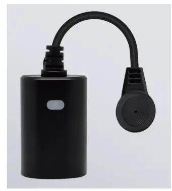
![]()
Specifications
| ITEM | INFORMATION |
| Model | MP22Z |
| Power Supply | AC 120V 60HZ |
| Signal(Frequency) | 908.42MHz |
| Range | Up to 100 feet line of sight between the Wireless Controller and the closest Z-Wave™ receiver module. |
| Operating Temperature Range | 5-104° F (-10-40° C) |
- Specifications subject to change without notice due to continuing product improvement
- Website:www.NIE-TECH.com/
Introduction
This product can be operated in any Z-Wave network with other Z-Wave Plus™ certified devices from other manufacturers.
All non-battery-operated nodes within the network will act as repeaters regardless of vendor to increase the reliability of the network. Each module is designed to act as a repeater, which will re-transmit a radio frequency (RF)
signal by routing the signal around obstacles and radio dead spots to ensure that the signal is received at its intended destination.
ZWA037-A is a security-enabled Z-Wave Plus™ device. Security Enabled Z-Wave Plus™ Controller must be used in order to fully utilize the product.
Endpoint ROOT Type
- GENERIC_TYPE: GENERIC_TYPE_SWITCH_BINARY(0x10)
- SPECIFIC_TYPE: SPECIFIC_TYPE_NOT_USED(0x00)
- APP ICON TYPE: ICON_TYPE_GENERIC_ON_OFF_POWER_SWITCH(0x0700)
Endpoint 1 Type
- GENERIC_TYPE: GENERIC_TYPE_SWITCH_BINARY(0x10)
- SPECIFIC_TYPE: SPECIFIC_TYPE_NOT_USED(0x00)
Endpoint 2 Type
- GENERIC_TYPE: GENERIC_TYPE_SWITCH_MULTILEVEL(0x11)
- SPECIFIC_TYPE: SPECIFIC_TYPE_COLOR_TUNABLE_MULTILEVEL(0x02)
Key Features
- Remote ON/OFF control via the Z-Wave™ controller
- Manual ON/OFF control
- Support Association Group and Auto Report switch status
- Support firmware upgrades via Over-the-air (need Gateways support)
- Support SmartStart
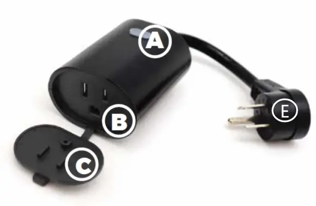
Product Overview
A. on/off button
B. Output Outlet
C. Protector
E. InPut
Button Definition
| ITEMS | Action (time unit: second) | Description |
| 1 | Tap one time [0.04,1] | Out of network: Z-Wave network inclusion(ADD) (send out NIF of full functionality ) In network: N/A In/Out of network: controls/toggles output on/off |
| 2 | Tap two times [0.04, 1] | Out of network: N/A In network: Z-Wave network exclusion(REMOVE: Send out NIF) . |
| 4 | Press and hold [5,10] | Enter RF power level test mode |
| 5 | Press and hold [15,20] | Reset to factory default setting and then send Device Reset Locally to primary controller. Note: Please use this procedure only when the network primary controller is missing or otherwise inoperable. |
| 6 | Press and hold [22,∞) | If still do not release the button, nothing will happen. LED should continue to pulse blue for unpaired state. |
- LED indicator
| Action | Press down Action Button | Release Action Button |
| Tap one time [0.04,1] | Solid Yellow Status | Turns on a solid yellow status, If a new node id is assigned to this device, the yellow LED will keep solid until whole network processing is complete (or entering. If successful, the LED will flash white -> green -> white -> green (at a rate of 250ms per each color change) for 2 seconds. After 2 seconds have finished, use typical paired status LED indicators for ON/OFF status from parameter #1. Control function: controls/toggles output on/off |
| Tap twotimes | Secure / Non-secure network: Purple Led keeps ON for 2 seconds and then OFF. | If the exclusion is successful, the Led will pulse a blue LED color based on unpair status. |
| Press and hold [1,1] | LED should revert back to LED state if paired or unpaired. | |
| Press and hold [2,5] | Solid orange status | LED should revert back to LED state if paired or unpaired. |
| Press and hold [5,9] | Solid cyan status | cyan led will remain solid upon releasing the button, which indicates the network quality is entering diagnosing, the led will be light up with 1 of 3 colors for 2 seconds after the diagnosing is complete. (Red = bad, Yellow = ok, Green = Good) |
| Press and hold [9,15] | Solid red led status | |
| Press and hold [15,20] | red color will blink on and off at a rate of 200ms for 2 seconds and then should pulse blue color based on unpair status. | Reset to factory default setting and then send Device Reset Locally to primary controller |
| Action | Press down Action Button | Release Action Button |
| Press and hold [22,∞) | Pulses Blue Color slowly based on unpaired status. |
Adding Your Device To Hub
- The device support two methods of inclusion, When using a Z-Wave Plus™ certified controller choose Network Wide Inclusion or SmartStart.
- TAP the button once to ADD/INCLUDE the device.
- Network Wide Inclusion To A Z-Wave™ Network
- TAP the button twice to REMOVE/EXCLUDE the device
- Refer to your primary controller instructions to process the inclusion/exclusion setup procedure.
- When prompted by your primary controller, click the Z-Wave button one times.
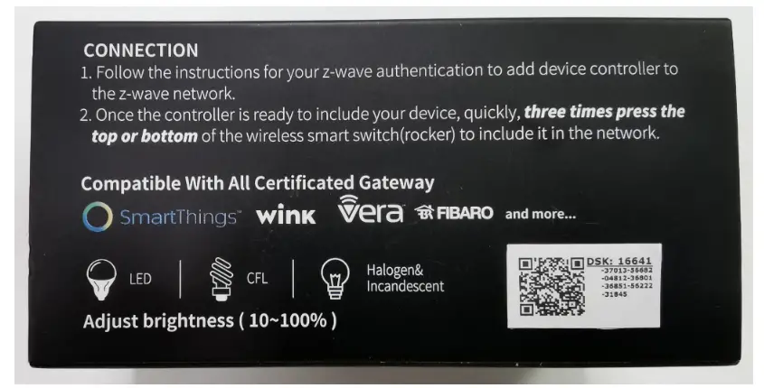
- The device is compatible with SmartStart.
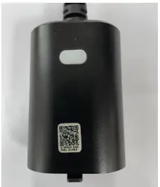
SmartStart-enabled products can be added into a Z-Wave™ network by scanning the Z-Wave QR Code found on the top of the outlet or the back of the box with a controller providing SmartStart inclusion. No further action is required and the SmartStart product will be added automatically within 10 minutes of being switched on and in the network vicinity.
QR Code and DSK
- The QR code are stocked to the side of the case, DSK is included in the QR code.
- The DSK code can be found on the DSK label which is attached on the packaging box.
| PACKAGE | DEVICE |
 |  |
Command Class
- Endpoint ROOT CC List
| Command Class Name | Version | Required Security Class |
| Z-Wave Plus Info | V2 | none |
| Security 2 | V1 | none |
| Supervision | V1 | none |
| Transport Service | V2 | none |
| Association | V2 | highest granted |
| Association Group Information | V3 | highest granted |
| Multi Channel Association | V3 | highest granted |
| Version | V3 | highest granted |
| Manufacturer Specific | V2 | highest granted |
| Device Reset Locally | V1 | highest granted |
| Power Level | V1 | highest granted |
| Indicator | V3 | highest granted |
| Firmware Update Meta Data | V5 | highest granted |
| Configuration | V4 | highest granted |
| Notification | V8 | highest granted |
| Multi Channel | V4 | highest granted |
| Switch Binary | V2 | highest granted |
| Clock | V1 | highest granted |
| Scene Activation | V1 | highest granted |
| Scene Actuator Configuration | V1 | highest granted |
- Endpoint 1 CC List
| Command Class Name | Version | Required Security Class |
| Z-Wave Plus Info | V2 | none |
| Security 2 | V1 | none |
| Supervision | V1 | none |
- Endpoint 2 CC List
| Command Class Name | Version | Required Security Class |
| Association | V2 | highest granted |
| Association Group Information | V3 | highest granted |
| Multi Channel Association | V3 | highest granted |
| Switch Binary | V2 | highest granted |
| Scene Activation | V1 | highest granted |
| Scene Actuator Configuration | V1 | highest granted |
| Notification | V8 | highest granted |
- Endpoint 2 CC List
| Command Class Name | Version | Required Security Class |
| Z-Wave Plus Info | V2 | none |
| Security 2 | V1 | none |
| Supervision | V1 | none |
| Association | V2 | highest granted |
| Association Group Information | V3 | highest granted |
| Multi Channel Association | V3 | highest granted |
| Color Switch | V3 | highest granted |
| Switch Multilevel | V4 | highest granted |
Basic Set Mapping
- Basic CC is mapped to Switch Multilevel CC and Binary Switch CC as below:
| Basic Set Node | Mapping |
| ENDPOINT ROOT | Binary Switch Set EP1 |
| ENDPOINT 1 | Binary Switch Set EP1 |
| ENDPOINT 2 | Multilevel Switch Set EP2 |
Indicator Command Class
- The indicator (blue color) will flashes according the indicator set command received from HUB.
| Indicator ID | Property ID |
| 0x50 (NODE IDENTIFY) | 0x03(ON OFF PERIOD) |
| 0x50 (NODE IDENTIFY) | 0x04(ON OFF CYCLES) |
| 0x50 (NODE IDENTIFY) | 0x05(ONE TIME ON OFF PERIOD) |
Notification
| Endpoint | Type | Events | Description |
| 0 | Heat Alarm(0x04) | 0x02(Overheat) | Air temperature is high. |
| 1 | Heat Alarm(0x04) | 0x02(Overheat) | Air temperature is high. |
Association Group
- Endpoint ROOT
| ID | Name | Node Count | Profile | Function |
| 1 | Lifeline | 5 | General: Lifeline | Device Reset Locally Notification Indicator Report Switch Multilevel Report Basic Report(Issued when Relay triggered by scene activation control) Switch Binary Report Switch Color Report Notification Report |
- Endpoint 1
| ID | Name | Node Count | Profile | Function |
| 1 | Lifeline | 0 | General: Lifeline | Switch Binary Report |
- Endpoint 2
| ID | Name | Node Count | Profile | Function |
| 1 | Lifeline | 0 | General: Lifeline | Switch Multilevel Report Switch Color Report |
- Group mapping
The endpoint 1 and 2’s Lifeline Group are mapped to the endpoint root’s lifeline.
Configuration Parameters
| Number | Name | Information | Format / Size | Read Only | Altering | Advanced | MIN | MAX | Default | Value Description |
|
0 1 |
Reaction of led |
Parameter setting to change the reaction of LED setting. |
1 byte unsigned integer |
NO |
NO |
NO |
0 |
4 |
2 | 0 – Disable LED completely 1 – Turn on between particular times only (Night Light Mode) 2 – Display ON/OFF status 3 – Display the reverse state of ON/OFF status 4 – Display always ON state |
|
02 |
Night led on time |
Night Light ON time. |
4 bytes unsigned integer |
NO |
NO |
NO |
0 |
0x00240 000 |
0x00180000 | Value setting =0xRRHHMMSS RR = reserved HH = Hours MM = Minutes SS = Seconds ● Default = 0x00180000 (6pm) |
|
03 |
Night led off time |
Night Light OFF time. |
4 bytes unsigned integer |
NO |
NO |
NO |
0 |
0x00240 000 |
0x00060000 | Value setting =0xRRHHMMSS RR = reserved HH = Hours MM = Minutes SS = Seconds ● Default = 0x00060000 (6am) |
|
04 | Indicator play duration |
Setting indicator play duration. | 1 byte unsigned integer |
NO |
NO |
NO |
0 |
255 |
0 | 0 – indicates that it is not blinking 1- 255 will set the duration and start the blinking process This sets the timeframe of blinking in seconds Once the duration ends, the blinking will stop and will set its configuration value back to 0 |
| 05 | Indicator speed | Select indicator flash speed. | 1 byte unsigned integer | NO | NO | NO | 1 | 24 | 5 | Sets amount of blinks per second If set to 5, it should blink 5 times per second Default = 5 |
| 07 | Control turn off | Prevents the plug from being turned off via its button. | 1 byte unsigned integer | NO | NO | NO | 0 | 2 | 0 | 0 – the plug will operate as normal and can be turned on or off 1 – the button on smart plug will be disabled for on and off commands, but still work for network removal or inclusion 2 – the plug will ignore any commands to turn it off AND it’ll ignore any use of the button (but the button will still work for network removal or inclusion) |
| 08 | Restore status after power failure | Action in case of power out. | 1 byte unsigned integer | NO | NO | NO | 0 | 2 | 0 | 0 – last status 1 – power on 2 – power off |
| 30 | Alarm setting | Determines if alarms are enabled in Switch, and what Switch will react to which alarms. | 1 byte unsigned integer | NO | NO | NO | 0 | 255 | 0 | 0 – Disable all alarm settings 1 – smoke alarm 2 – CO alarm |
| 31 | Alarm response in device | Enabled by (Alarm settings), and determines what the switch does in the case an alarm is triggered. | 1 byte unsigned integer | NO | NO | NO | 0 | 255 | 0 | 0 – disable, no reaction to alarm settings 1 – Switch is ON … 2 – Switch is OFF … 3 – 255: Sets rate at which Switch turns ON and OFF in seconds (ie. if set to 3, then switch will turn ON in 0.3 seconds, and then turn OFF in 0.3 seconds in a cycle until user disables the alarm manually, if set to 255, then it will cycle every 25.5 seconds) |
| Number | Name | Information | Format / Size | Read Only | Altering | Advanced | MIN | MAX | Default | Value Description |
| 32 | Alarm disable setting | Determines the method of disabling the alarm of the device. | 1 byte unsigned integer | NO | NO | NO |
0 | 255 | 1 | 0 – Can be disabled by 1x tapping switches action button once 1- Can be disabled by 2x tapping Switches action button within 1 second 2 – Can be disabled by 4x tapping Switches action button within 2 seconds 3 – Can be disabled by pressing and holding Switches action button for 10 seconds 5 – 255: Sets the duration of the alarm in seconds (ie. Customer sets this setting to 50, the alarm state of the Switch will disable after 50 seconds) |
| 40 | Auto turn off timer | Auto off after as soon as the switch turns ON. | 4 byte unsigned integer | NO | NO | NO | 0 | 86400 | 0 | 0 – no auto off with timer … 1- 86400 seconds |
| 41 | Auto turn on timer | Auto on after as soon as the switch turns OFF. | 4 byte unsigned integer | NO | NO | NO | 0 | 86400 | 0 | 0 – no auto on with timer … 1- 86400 seconds |
FCC
Federal Communications Commission (FCC) Statement FCC Caution: Any changes or modifications not expressly approved by the party responsible for compliance could void the user’s authority to operate this equipment.
This device complies with Part 15 of the FCC Rules. Operation is subject to the following two conditions: (1) This device may not cause harmful interference, and (2) this device must accept any interference received, including
interference that may cause undesired operation.
NOTE: This equipment has been tested and found to comply with the limits for a Class B digital device, pursuant to Part 15 of the FCC Rules. These limits are designed to provide reasonable protection against harmful
interference in a residential installation. This equipment generates, uses and can radiate radio frequency energy and, if not installed and used in accordance with the instructions, may cause harmful interference to radio communications. However, there is no guarantee that interference will not occur in a particular installation. If this equipment does cause harmful interference to radio or television reception, which can be determined by turning the equipment off and on, the user is encouraged to try to correct the interference by one or more of the following measures: Reorient or relocate the receiving antenna. Increase the separation between the equipment and receiver. Connect the equipment into an outlet on a circuit different from that to which the receiver is connected. Consult the dealer or an experienced radio/TV technician for help. This equipment should be installed and operated with minimum distance 20cm between the radiator and your body.
WARNING
RISK OF FIRE
RISK OF ELECTRICAL SHOCK
RISK OF BURNS
CONTROLLING APPLIANCES:
EXERCISE EXTREME CAUTION WHEN USING Z-Wave™ DEVICES TO CONTROL APPLIANCES. OPERATION OF THE Z-Wave™ DEVICE MAY BE IN A DIFFERENT ROOM THAN THE CONTROLLED APPLIANCE, ALSO ANUNINTENTIONAL ACTIVATION MAY OCCUR IF THE WRONG BUTTON ON THE REMOTE IS PRESSED. Z-Wave™ DEVICES MAY AUTOMATICALLY BE POWERED ON DUE TO TIMED EVENT PROGRAMMING. DEPENDING UPON THE APPLIANCE, THESE UNATTENDED OR UNINTENTIONAL OPERATIONS COULD POSSIBLY RESULT IN A HAZARDOUS CONDITION. FOR THESE REASONS, WE RECOMMEND DO NOT RETURN THIS PRODUCT TO THE STORE THE FOLLOWING: DO NOT USE Z-Wave™ DEVICES TO CONTROL ELECTRIC HEATERS OR ANY OTHER APPLIANCES WHICH MAY PRESENT A HAZARDOUS CONDITION DUE TO UNATTENDED OR UNINTENTIONAL OR AUTOMATIC POWER ON CONTROL.


