![]()
DTU-W100 3 Gen Wi-Fi Model
User Manual
Important Safety Information
Read this First
This manual includes important instructions for installing and maintaining the Hoymiles Data Transfer Unit (DTU).
Safety Instructions
| Symbol | Usage |
 | Indicates a hazardous situation that can result in deadly electric shock hazards, other serious physical injuries, or fire hazards. |
 | Indicates directions that must be fully understood and followed in entirety to avoid potential safety hazards including equipment damage or personal injury. |
 | Indicates this points out that the described operation must not be carried out. The reader should stop, use caution, and fully understand the operations explained before proceeding. |
- Note that only professionals can install or replace DTU.
- Do not try to repair DTU without Hoymiles’ approval. If DTU is damaged, please send the DTU back to your installer for repairing/replacement. Disassembling DTU without Hoymiles’ approval will invalidate the remaining warranty period.
- Please read all instructions and warnings on the technical specifications carefully.
- Do not use Hoymiles products in a way that is not suggested by the manufacturer. Doing so may cause death or injury to persons or damage to equipment.
User
This manual is only for professional installation and maintenance personnel to use.
Support and Contact Information
If you have technical queries concerning our products, please contact your system installer or distributor. If further support is required, contact Hoymiles’ support at this link.
- www.hoymiles.com
- Homilies customer service center: [email protected]
Other Information
Product information is subject to change without notice. The user manual will be updated frequently, and please refer to Hoymile’s official website at www.hoymiles.com for the latest version.
About Hoymiles Microinverter System
The Microinverter
It converts the DC output of solar modules into grid-compliant AC power. It sends the output information of PV panels and the operation data of the microinverters to the DTU, which is the hardware basis of the panel-level monitoring.
With conversion efficiency up to 96.7% and MPPT efficiency up to 99.9%, Hoymiles microinverters rank in the first class of the world’s Microinverter industry.
The DTU
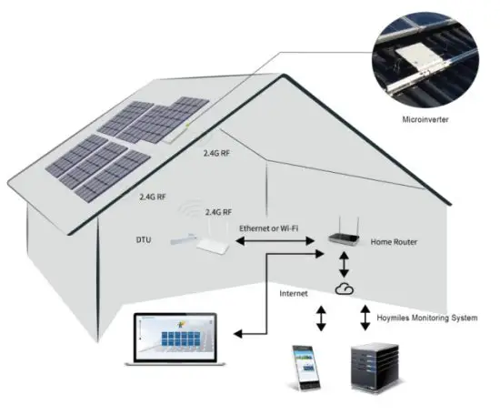
The DTU is the key component in Hoymiles microinverter system. It works as the communication gateway, which operates between the Hoymiles microinverters and the Hoymiles Monitoring Server. The DTU communicates with the microinverter wirelessly via 2.4GHz Proprietary RF (Nordic), collecting the operation data of the system. Meanwhile, the DTU connects to the Internet via router and communicates with Hoymiles Monitoring Server. The microinverter system operation data will be uploaded to Hoymiles Monitoring Server via DTU.
The Homilies Monitoring Server
It collects the operation data and status of the microinverters in the system and provides panel-level monitoring for the users and maintenance staff. The following diagram shows the Hoymiles Microinverter system.
DTU Installation
System Capacity
The DTU is capable of monitoring up to 99 pieces of a single unit or 49 pieces of two in one unit or 24 pieces of four in one unit. If the communication between the DTU and microinverter is caused by the installation conditions, the number of PV modules that the DTU can monitor may be reduced.
Basic Conditions Required
Before installing the DTU, ensure the site meets the following requirements:
- Install close to the router.
- Stable Internet reception.
- The straight distance between DTU and Microinverter shall be less than 5 meters.
- The location should be one meter above the ground, 0.8 meters away from the corner.
The environmental requirements for DTU installation:
- Away from dust, liquid, acidic, or corrosive gas.
- Temperature is between -20ºC and 55ºC
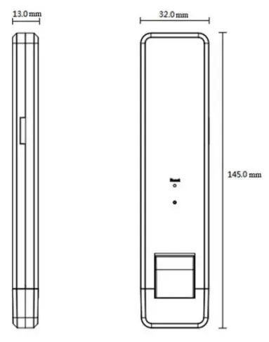
Dimensions
Interface Layout
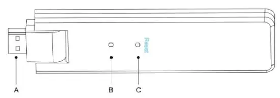
| Item | Description |
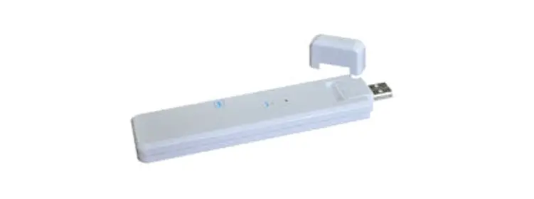
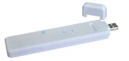
| A | USB Connector |
| B | Status Indicator |
| C | Reset Bottom |
Local Install Assistant
Local Install Assistant is a new function integrated with DTU-W100 3rd Gen, please download the Installer App (for installer/distributor use only) first.

http://m.hoymiles.com/download_installer.html
DTU-W100 has improved from the previous generation of DTU products, and developed with this a new function that allows installer:
A. One step to complete the WiFi configuration;
B. Station overall Inverters status indication allows the installer to see how many MI under this
DTU is working properly (and the details for each MI) and how many are abnormal (and the details for each MI) with one glance of the eyes;
C. Add the Connection status, which will display the signal strength between each MI with connected DTU, so that installer can adjust the DTU installation location accordingly. This function will simplify the DTU installation, and avoid the second visit for the installer due to the poor connection between DTU and certain MI.
Note: Please refer to “Hoymiles Local Install Assistant Technical Note” for more details.
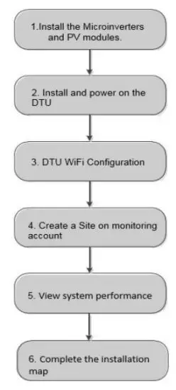
System Installation Sequence
The DTU is capable of monitoring up to 99 pieces of a single unit or 49 pieces of two in one unit or 24 pieces of four in one unit.
DTU Installation Procedure
- Install the PV Modules and microinverters
Please refer to the Microinverter’s Manual or Quick Installation Guide for the detailed installation steps. - Locate the DTU
The maximum communication distance of Hoymiles DTU is 150m in open space. The walls, roofs, or other obstacles in between will affect the signal and reduce the communication distance in the real installation.
The range of signal reduction for possible obstacles at the site has been shown below:Material Relative signal range reductions Wood/Glass 0-10% Stone/Pressed cardboard 10%-40% Reinforced concrete (reduction increases with the amount of reinforcement) 10%-90% Metal Up to 100% Therefore, the DTU shall be placed as close to the microinverters as possible at the site to ensure good communication between DTU and microinverters.
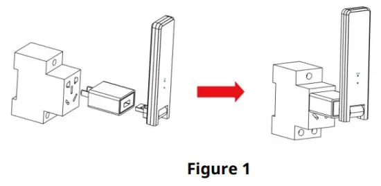
- DTU Installation
a. Connect the DTU to the adapter and plug it into the wall socket. (Figure 1) b. If using Power Strip, please make sure it is placed at least 1 meter above the ground and try to install the DTU 90 degrees vertical to the ground as much as possible (figure 2).
 Note: Please do not install the DTU direct above the metal or concrete to prevent the signal dilution.
 - Start Procedure
Once the DTU is powered on, the red, green, and blue lights will flash every one second in turns for 30 seconds. - WiFi Configuration
Use the smartphone/tablet open the Installer App and log in. Approach “Me” at the bottom of the page and then “Network Configuration”. And input the house router’s Network name and password, click “Send to DTU” to complete the WiFi configuration.
 b. If using Power Strip, please make sure it is placed at least 1 meter above the ground and try to install the DTU 90 degrees vertical to the ground as much as possible (figure 2).
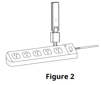 Note: Please do not install the DTU direct above the metal or concrete to prevent the signal dilution.
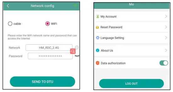
Site creation on HMP
A. Install Hoymiles Installer APP by searching “Hoymiles” at the App Store (IOS) or Play Store (Android).
B. Open the APP and login in with your installer account name and password. If you are a new installer with Hoymiles, please apply an Installer account from your distributor in
advance.
C. Add Station, select the “Station” tab on the bottom, then select “⊕” on the right top side of the page.
D. Select “Quick” for Single-DTU and “Profession” for Multi-DTU.
E. Please fill in the station details accordingly, and press “Next” after completed.
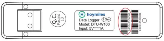
F. Press “Add DTU ID”, scan the DTU ID (or you can manually input ID), and press “Next” after complete.
G. Click “Start binding” and choose the angle and tilt based on the installation.
H. Scan the Microinverter ID (or you can manually input the ID) and click the tick after completing each ID input. Press “Finish” once all Microinverter ID has been input.
I. Disable the Scan function on the top of the right-hand side and design the Layout base on the installation. Click the tick box on the top of the right-hand side, and then select “Next” after completing the design.
J. Upload a picture of the site and select “Finish” to complete the site creation.
K. The new site will appear on the Station list from the Installer account.
L. Please click the “Networking” button after the power station is created.
M. Please wait about 30 minutes, the station will show online, and all the MI-IDs are found.
Customer Login
A. Please download the End User App. You can search “Hoymiles” at the App Store (IOS) or
Play Store (Android).
B. Log in with the Password and Username that has been set up by the Installer on the previous step (Section 6 step e), and press “Login”.
C. Customers will be able to view all details once the data start to upload, normally it will need around 30 minutes for the first data to come through.
D. Customers can also view the Microinverter generating details via accessing the HMP monitoring platform website at https://world.hoymiles.com.
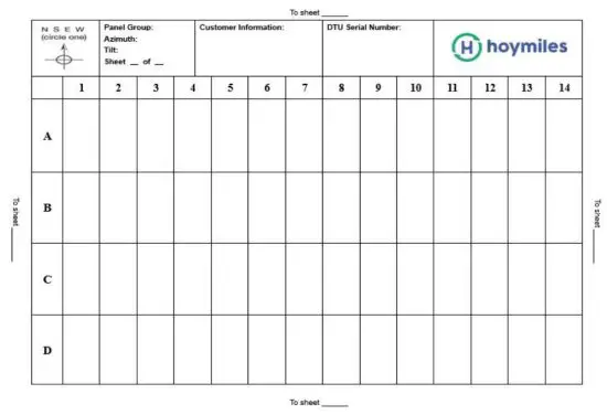
Complete Installation Map
When the system is energized, and the DTU detects the microinverters, you need to complete the installation map.
A. Peel the serial number label from the DTU and place it on the installation map.
B. Complete system information of the installation map shown below.
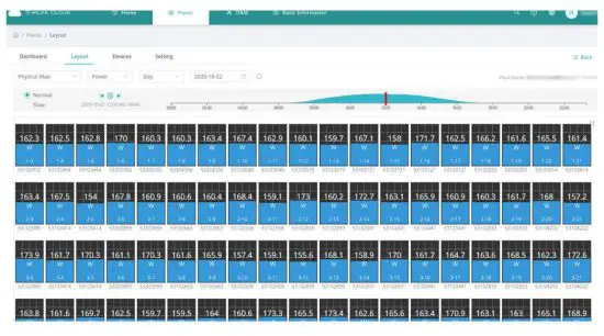
Browse the Web Station
You can view the inverter’s real-time operating details on the computer web page by accessing
Hoymiles online monitoring platform at https://world.hoymiles.com.
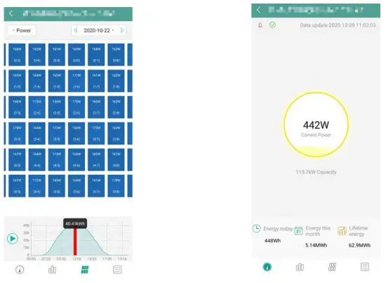
View Phone APP
Download the mobile phone APP by searching “Hoymiles” at App Store (IOS) or Play Store (Android), log in with the customer/installer account name and password, and all installed Microinverters operating details will be able to view from there.
LED indicator working status description
| Red Light | Description |
| Flashes every 1 second | DTU disconnect WiFi |
| Flashes every 0.5 seconds | DTU disconnect with server |
| Blue Light | Description |
| Flashes every 1 second | No ID |
| Flashes every 0.5 seconds | Received data From server |
| Green Light | Description |
| Flashes every 0.5 seconds | The search ID is incomplete |
| Lights up constantly | Normal |
| RED+GREEN+BLUE | Description |
| Each color flashes once every 1 second | Power on |
| Each color flashes twice every 1 second | Firmware upgrade |
Troubleshooting
| Indicator | Status | Description | Solution |
| Red | LED flash in Red every 1 second | DTU has no ID inside and disconnects from Wi-Fi |
|
| LED lights up in Red constantly | W100 with ID inside but no Wi-Fi connection | ||
| LED flashes in Red every 0.5 seconds | DTU disconnect with server |
|
| Blue | LED lights up in Blue constantly: | W100 has Wi-Fi connection but without ID inside. |
|
| LED flashes in Blue every 1 second: | No ID |
| |
| Green | LED lights up in Green every 0.5 seconds: | The search ID is incomplete |
|
Note: Network Connection:
- Connected to Wi-Fi, the blue indicator lights up, and then you can build the power station;
- Can’t connect to Wi-Fi, the indicator lights up as red + blue alternately flashing, and then you need to connect to Wi-Fi again.
Datasheet
| Model | DTU-W100 |
| Communication to Microinverter | |
| Communication method | 2.4GHz Proprietary RF (Nordic) |
| Maximum distance (open space) | 150m |
| Maximum number of inverters connected | 99 panels |
| Communication to Cloud | |
| WIFI communication standard | WiFi (802.11b/g/n) |
| Data upload time | 15 minutes |
| Power Supply (Adapter) | |
| Power supply | External Adapter with USB port |
| Adapter input voltage/frequency | 100 to 240 V AC / 50 or 60Hz |
| Adapter output voltage/current | 5V / 2A |
| Power consumption | 1.0W (typical), 5W(maximum) |
| Mechanical Data | |
| Ambient temperature range (°C) | -20°C to 55°C |
| Size (W×H×D) | 143mm×33mm×12.5mm |
| Weight (KG) | 0.1 |
| A fixed way | Direct power supply |
| Indicator light | LED |
| Others | |
| Standard | EN60950 EN61000-3-2 EN61000-3-3 |
| FCC 15B / 15C | |
© 2019 Hoymiles Power Electronics Inc. All rights reserved.


