![]()
USER MANUAL Near Field Communication
Reader NFC 3.0
System Description
Continental Near Field Communication Reader is developed for automotive applications under the name NFC 3.0 which includes the following function:
– NFC: Near Field Communication
The NFC 3.0 module and its implementation inside the vehicle is depicted in Fig. 1. Its assembly instruction is done by professional workers. Therefore, the product cannot be moved or switched to another position by the end-user.
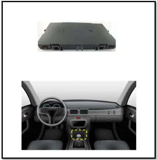 Fig. 1: NFC 3.0 module and its implementation inside the vehicle
System overview
NFC 3.0 product is an NFC reader used for establishing a communication with adequate devices at a frequency of 13.56MHz. This communication realized between a base station unit and a mobile device is based on near field magnetic induction between transmitter and receiver coils.
Base station comprises two main functional units, namely a power conversion unit and a Communications & Control unit for delivering, controlling, and regulating the transferred power.
Mobile device comprises a power pick up unit and a communications & control unit for achieving power requirements and establishing an active NFC communication.
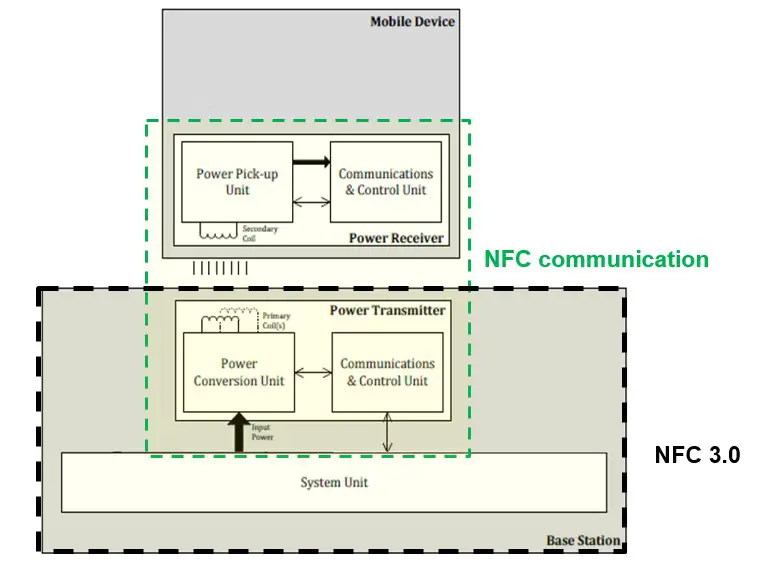 Fig. 2: NFC Wireless power transfer structure
Near Field Communication Reader description
The NFC 3.0 is mainly composed of 4 parts as depicted in Fig.3:
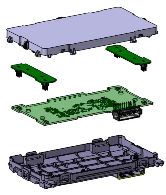
Fig. 3: NFC 3.0 split view
- Top housing
- Antenna PCB
- Main PCB with 8 ways connector
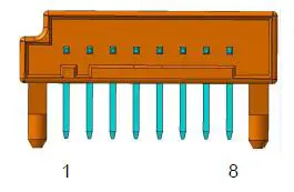
Fig. 4 Connector diagram
| Pin No | Function | Type | Description |
| 1 | VBAT | Supply | General supply battery connection |
| 2 | NC | Nat used | Not used |
| 3 | CANJI | Communication | CAN communication high signal |
| 4 | CAN_L | Communication | CAN communication low signal |
| 5 | NC | Not used | Not used |
| 6 | OND BAT | Supply | General supply GND connection |
| 7 | NC | Not used | Not used |
| 8 | NC | Not used | Not used |
Fig. 5 Connector pin description
4. Bottom Housing
A picture of a serial production part is shown in Fig. 6:
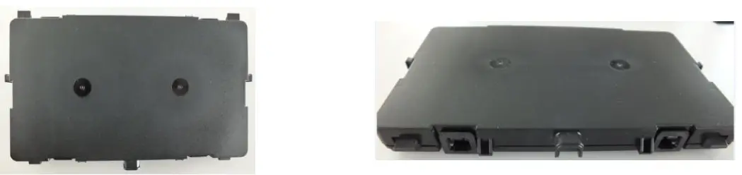
A picture of a serial production part is shown in Fig. 6:
NFC architecture
The NFC 3.0 integrates only one NFC transceiver emitting at a frequency of 13.56MHz. It is connected via switches to a Main NFC antenna and two side NFC antenna (Side 1 and Side 2).
Product parameters
Below in table 1, the technical parameters of the NFC 3.0 product are specified:
| Parameters | Values |
| Supply voltage | 12V battery |
| Voltage supply range | 8V < Vbat < 16V |
| Max. power consumption | 6W |
| Product Operating temperature range | -40°C < Temp < 85°C |
| Max. Current consumption | 250 mA |
| Vehicle fuse protection | 7.5 A |
| Product Weight | 104 g |
| Dimensions (X/Y/Z in mm) | 139/80/17.5 (25 at Power supply connector) |
Table 1: Product parameters of NFC 3.0
NFC technical parameters
Below in table 2, the technical parameters of the NFC feature of NFC 3.0:
| Parameters | Values |
| Carrier frequency | 13.56 MHz |
| Modulation type | Amplitude Shift Keying (ASK) |
| Data rate max. | 848 kbps |
| NFC chipset brand | NXP Semiconductors |
| NFC chipset model number | NCF3340EHN |
| Max H field @10m (@13.56MHz) | 1.5 dBµA/m |
| Max output power (EIRP) | 2.32µW |
Table 2: NFC technical parameters of NFC 3.0
NFC antenna
The NFC block is composed of three antennas: Main, Side1 and Side 2 antenna.
The electrical parameters of the NFC antenna are listed in the following tables:
Main NFC antenna:
| Parameters | Values |
| Antenna type | Planar printed coil on PCB |
| Number of turns | 3 |
| Antenna size | 110mm x 62 mm |
| Antenna Gain (dBi) @ 13.56MHz | -4420.00% |
Table 3: Main NFC antenna technical parameters
Side 1 NFC antenna:
| Parameters | Values |
| Antenna type | Planar printed coil on PCB |
| Number of turns | 3 |
| Antenna size | 60mm x 13.8mm x 10mm |
| Antenna Gain (dBi) @ 13.56MHz | -5707.00% |
Table 4: Side 1 NFC antenna technical parameters
Side 2 NFC antenna:
| Parameters | Values |
| Antenna type | Planar printed coil on PCB |
| Number of turns | 3 |
| Antenna size | 60mm x 13.8mm x 10mm |
| Antenna Gain (dBi) @ 13.56MHz | -5858.00% |
Table 5: Side 2 NFC antenna technical parameters
Variants and versions of “NFC 3.0”
NFC 3.0: includes NFC function with only one version as described below:
| Ref | NFC | Top View | Bottom View |
| NFC 3.0 | Yes | 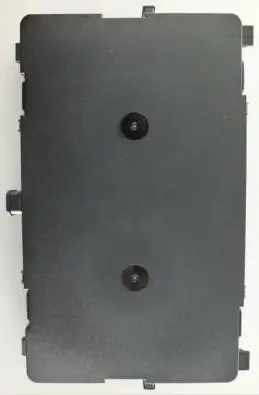 | 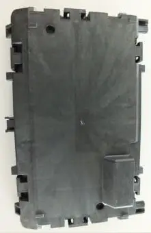 |
Table 6: NFC 3.0 overview
LABEL CONTENT
BRAZIL
![]()
HHHHH-AA-FFFFF
CANADA
This device complies with part 15 of the FCC Rules and Industry Canada license-exempt RSS standard(s). Operation is subject to the following two conditions:
- This device may not cause harmful interference, and
- this device must accept any interference received, including interference that may cause undesired operation.
SINGAPORE
| Complies with IMDA Standards (Dealer’s Licence No) | Gomplies with IMDA Standards DB123456 |
SOUTH AFRICA
![]()
TA-YEAR/XXXX
TAIWAN
Taiwan regulatory information(NCC)
Article 12
Without permission granted by the NCC, any company, enterprise, or user is not allowed to change frequency, enhance transmitting power or alter original characteristic as well as performance to a approved low-power radio-frequency devices.
Article 14
The low power radio-frequency devices shall not influence aircraft security and interfere legal communications; If found, the user shall cease operating immediately until no interference is achieved.
The said legal communications means radio communications is operated in compliance with the Telecommunications Act.
The low-power radio-frequency devices must be susceptible with the interference from legal communications or ISM radio wave radiated devices.
USA
“This device complies with part 15 of the FCC Rules and Industry Canada license-exempt RSS standard(s). Operation is subject to the following two conditions:
- This device may not cause harmful interference, and
- this device must accept any interference received, including interference that may cause undesired operation.”
FCC § 15.21 Information to user
“Changes or modifications not expressly approved by the party responsible for compliance could void the user’s authority to operate the equipment.”
RF Exposure Requirements
To comply with FCC RF exposure compliance requirements, the device must be installed to provide a separation distance of at least 20 cm from all persons.


