Continental WCA NFC 2.0 Multi-Functional Smartphone Terminal
System Description
Continental Wireless Power Charger is developed for automotive applications under the name WCA NFC 2.0 which includes two functions like:
- WPC: Wireless power charger; WPC Function 126.6kHz
- NFC: Near Field Communication; NFC Function 13.56MHz
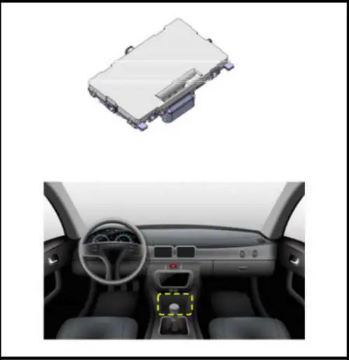
The WCA NFC 2.0 module and its implementation inside the vehicle is depicted in Fig. 1. Its assembly instruction is done by professional workers. Therefore, the product cannot be moved or switched to another position by the end user.
 \
\
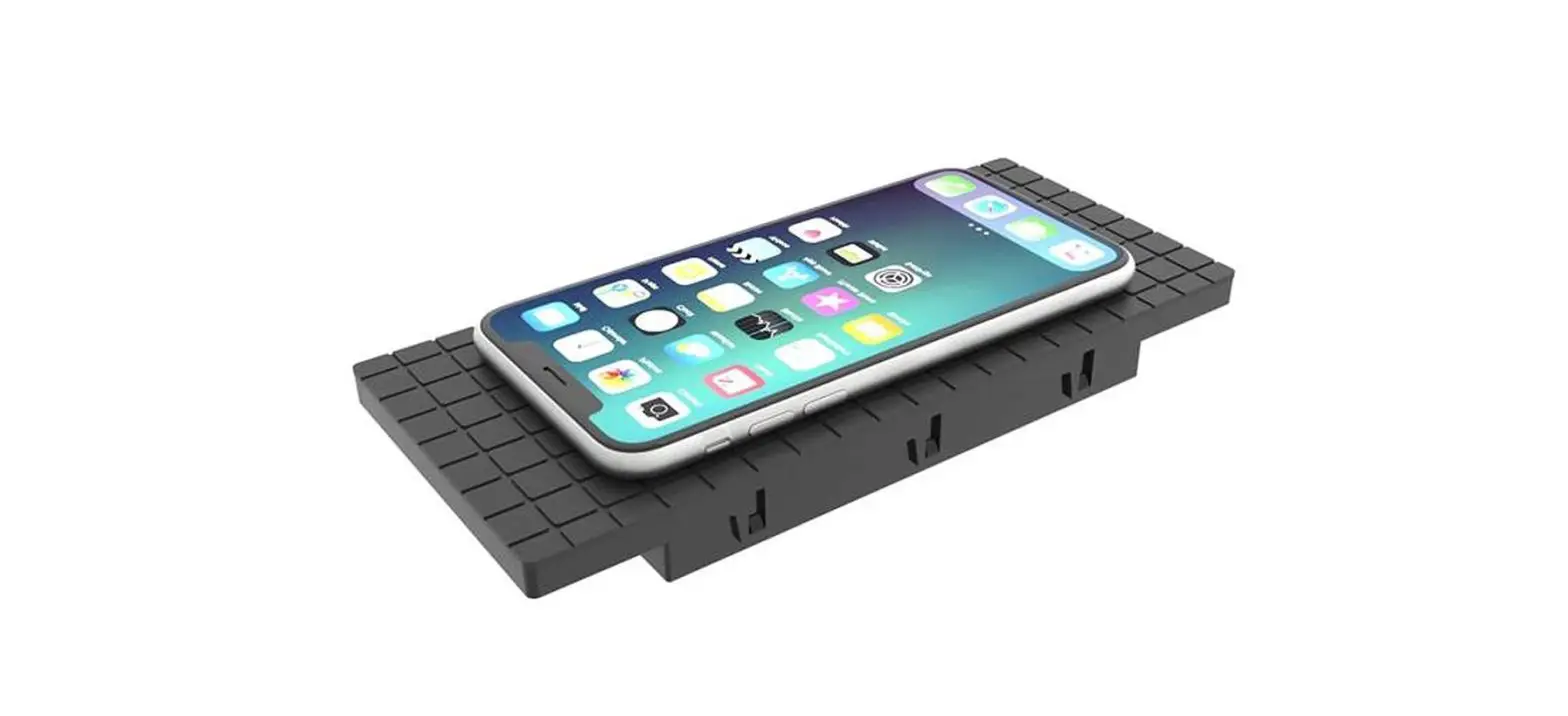
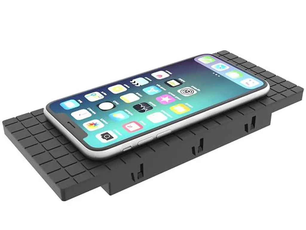
WCA NFC 2.0 charger uses Qi standard of Wireless Power Consortium (WPC) for enabling wireless charging from a base station unit to mobile device. The power transfer method is based on near field magnetic induction between coils.
System Overview
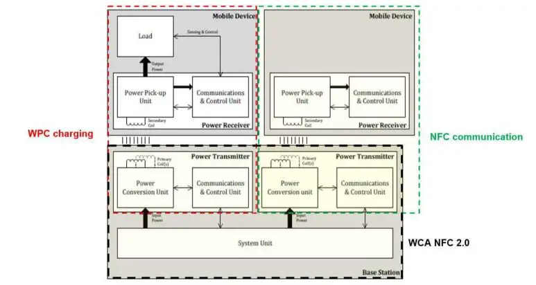
- The structure of wireless power transfer proposed in Fig. 2 shows an overview of the system with two kinds of distinguished devices: Base station and Mobile device.
- Base station comprises two main functional units per mode (WPC and NFC), namely power conversion units and Communications & Control units for delivering, controlling and regulating the transferred power.
- Mobile device (power receiver) comprises a power pick up unit and a communications & control unit for achieving power requirements and charging the device battery if is chargeable device or establishing an active NFC communication.
Wireless Power Charger Description
The WCA NFC 2.0 is mainly composed of 6 parts as depicted in Fig.3.
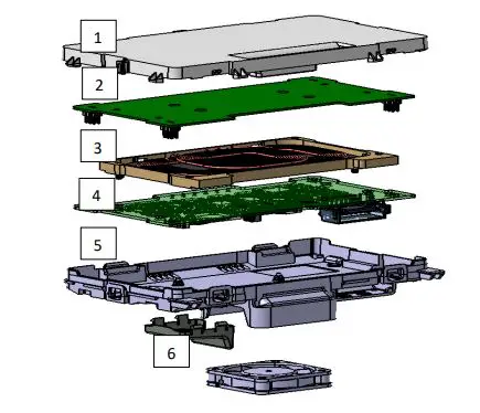
- Top housing
- Antenna PCB
- WPC coil + Ferrite + Plastic Holder
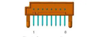
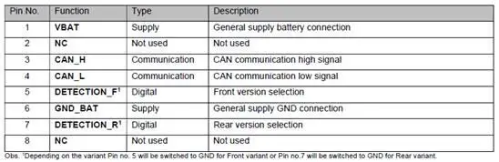
- Main PCB with 8 ways connector: diagram below in Fig 4, pins description in Table1.


5. Bottom Housing + Fan cover
6. Fan
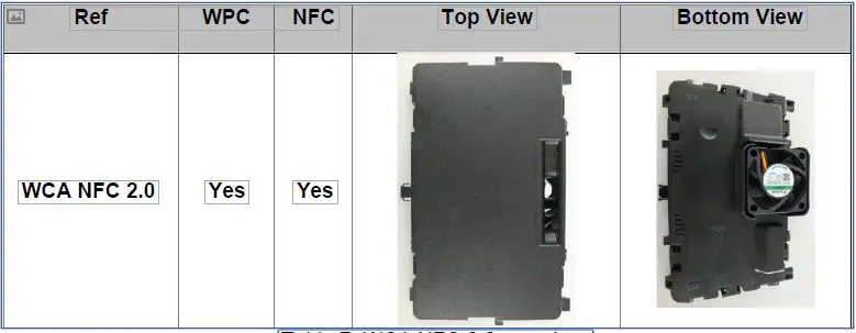
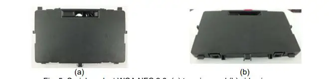
A picture of a serial production part is shown in Fig. 5.
WCA NFC 2.0 modes
According to the Qi standard, a simple operational description of wireless power transfer can be summarized in two principle operational modes:
- The first mode with a defined burst sequence allows the transmitter to detect an object on the charging surface: IDLE mode
- The second mode allows the power transfer from the base station to the mobile device, placed on the charging surface: Charging mode
The transition between these two modes is realized through a transient mode: Detection mode. which only occurs when the Mobile device is placed on the charging surface.
Product parameters
Below in table 2, the technical parameters of the WCA NFC 2.0 product are specified:
| Parameters | Values |
| Supply voltage | 12V battery |
| Voltage supply range | 8V < Vbat < 16V |
| Max. power consumption | 30W |
| Product Operating temperature range | -40°C < Temp < 85°C |
| Max.current consumption | 3A |
| Vehicle fuse protection | 7.5A |
| Product weight | 230 g |
| Dimensions (X/Y/Z in mm) | 139/80/17.5 (31.5 at FAN level) |
WPC parameters
Below in table 3, the technical parameters of the WPC feature are specified:
| Parameters | Values |
| Carrier frequency | 126.6 kHz |
| Frequency shift | +/- 6 kHz |
| WPC chipset brand | IDT |
| Data rate max (FSK) | 0.247 kbps |
| WPC litz coil | MPA21 Triple coil according to Qi Standard |
| WPC litz coil gain @ 126.6kHz | -108.4 dBi |
| Max. output power | 15W |
| Max. H field @10m (@ 126.6kHz) | 7.3 dBµA/m |
NFC Parameters
Below in table 4, the technical parameters of the NFC feature of WCA NFC 2.0:
| Parameters | Values |
| Carrier frequency | 13.56 MHz |
| Modulation type | Amplitude Shift Keying (ASK) |
| Data rate max. | 848 kbps |
| NFC chipset brand | NXP Semiconductors |
| NFC chipset model number | NCF3340EHN |
| Max. H field @10m (@ 13.56 MHz) | 4 dBµA/m |
NFC antenna
- The NFC block is composed of three antennas: Main, Side1 and Side 2 antenna.
- The electrical parameters of the NFC antenna are listed in the following tables (5,6 and 7):
Main NFC antenna:
| Parameters | Values |
| Antenna type | Planar printed coil on PCB |
| Number of turns | 3 |
| Antenna size | 106mm x 52 mm |
| Antenna Gain (dBi) @ 13.56MHz | -51.38 |
| Table 5: Main NFC antenna technical parameters | |
Side 1 NFC antenna:
| Parameters | Values |
| Antenna type | Planar printed coil on PCB |
| Number of turns | 3 |
| Antenna size | 59mm x 13.8mm x 10mm |
| Antenna Gain (dBi) @ 13.56MHz | -58.58
|
Side 2 NFC anteena
| Parameters | Values |
| Antenna type | Planar printed coil on PCB |
| Number of turns | 3 |
| Antenna size | 59mm x 13.8mm x 10mm |
| Antenna Gain (dBi) @ 13.56MHz | -57.07 |
Overview of “WCA NFC 2.0”
Here below the product overview of “WCA NFC 2.0”: