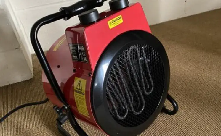
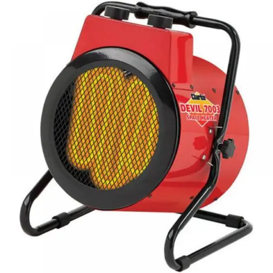
Clarke DEVIL 7003 3KW Electric Fan Heater
INTRODUCTION
Before attempting to use this product, please read this manual thoroughly and follow the instructions carefully.
GUARANTEE
This product is guaranteed against faulty manufacture for a period of 12 months from the date of purchase. Please keep your receipt which will be required as proof of purchase.
This guarantee is invalid if the product is found to have been abused or tampered with in any way, or not used for the purpose for which it was intended.
Faulty goods should be returned to their place of purchase, no product can be returned to us without prior permission.
This guarantee does not effect your statutory rights.
ENVIRONMENTAL RECYCLING POLICY
Through purchase of this product, the customer is taking on the obligation to deal with the WEEE in accordance with the WEEE regulations in relation to the treatment, recycling & recovery and environmentally sound disposal of the WEEE.
In effect, this means that this product must not be disposed of with general household waste. It must be disposed of according to the laws governing Waste Electrical and Electronic Equipment (WEEE) at a recognized disposal facility.
THE FOLLOWING TABLE ADDRESSES THE INFORMATION REQUIREMENTS OF REG.2015/1188
| Item | Symbol | Value | Unit |
| Heat output | |||
| Measured seasonal space heating energy efficiency | 36% | ||
| Nominal heat output | Pnom | 3 | kW |
| Minimum heat output (indicative) | P min | 1.5 | kW |
| Maximum continuous heat output | P max | 3 | kW |
| Auxiliary electricity consumption | |||
| At nominal heat output | elmax | n/a | kW |
| At minimum heat output | el min | n/a | kW |
| In standby mode | elSB | n/a | kW |
| Type of heat input for electric storage local heaters only | |||
| Manual heat charge control with integrated thermostat | No | ||
| Manual heat charge control with room and/or outdoor temperature feedback | No | ||
| Electronic heat charge control with room and/or outdoor temperature feedback | No | ||
| Fan assisted output | No | ||
| Type of heat output/room temperature control (select one) | |||
| Single stage heat output, no temperature control | No | ||
| Two or more manual stages, no temperature control | No | ||
| With mechanical thermostat temp control | Yes | ||
| With electronic temperature control | No | ||
| Electronic temperature control with day timer | No | ||
| Electronic temperature control with week timer | No | ||
| Other control options (multiple selections possible) | |||
| Room temperature control with presence detection | No | ||
| Room temperature control with open window detection | No | ||
| Room temperature control with distance control option | No | ||
| Room temperature control with adaptive start control | No | ||
| Room temperature control with working time limitation | No | ||
| Room temperature control with black bulb sensor | No | ||
SAFETY SYMBOLS
The following symbols appear on the unitt.
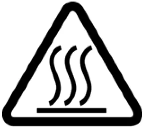
- Hot Surface, Do Not Touch

- Do Not Cover


SAFETY RULES
Make sure that you read, understand and comply with the following.
ELECTRICAL SAFETY
WARNING: THIS HEATER MUST BE EARTHED
- Regularly inspect the power cable / plugs and all electrical connections for signs of damage/looseness. Do not use the heater it the power cable is damaged.
- Minimize the risk of electric shock by installing a RCCB (Residual Current Circuit Breaker) and a suitable isolator into the main distribution board.
- Make sure that the voltage on the rating plate is the same as the voltage of the power supply. If in doubt, consult a qualified electrician.
- Do not abuse the electrical cable. Never use the cable for pulling or unplugging the heater.
- Keep the cable away from sources of heat, oil, sharp edges or moving parts. Damaged or tangled cables increase the risk of electric shock.
- Do not use extension cables with this heater.
MAINTENANCE
WARNING: DISCONNECT THE HEATER FROM THE POWER SUPPLY, BEFORE SERVICING OR PERFORMING ANY MAINTENANCE. SERVICING OR MAINTENANCE MUST ONLY BE CARRIED OUT BY THE CLARKE SERVICE DEPARTMENT.
- Check that the heater is in good working order. Take immediate action to repair or replace damaged parts.
- Do not allow the heating elements to become covered with dust which could become a fire hazard. If used in a dusty workplace it should be cleaned as described under Cleaning and Maintenance.
- Use recommended parts only. Unapproved parts may be dangerous and will invalidate the warranty.
- DO NOT attempt to repair a damaged heater, contact the Clarke service department.
POSITIONING
WARNING: DO NOT USE THE HEATER NEAR FLAMMABLE MATERIAL, LIQUIDS, SOLIDS, GASSES OR COMPRESSED GAS CYLINDERS ETC.
- Heater is designed for indoor use only.
- DO NOT place the heater close to a bath, wash basin, shower, swimming pool or any other water-filled area or wet surface. DO NOT place the heater up against any surface such as a wall, door or furniture etc.
- DO NOT place the heater immediately below any electrical outlet.
- NEVER place the heater near combustible materials such as curtains, furniture etc. Allow at least 2 meter clearance.
- DO NOT place the heater on a raised surface or anywhere where it could topple over
- Take care to ensure that the grille cannot be blocked by curtains or other fabrics.
- Do not operate fan heaters in explosive atmospheres such as in the presence of flammable liquids, gasses or dust such as in a paint spray booth or any explosive environment. Electric motors create sparks which may ignite dust or fumes.
COMMON SENSE
- DO NOT operate the heater when you are tired or under the influence of alcohol, drugs or intoxicating medication.
- DO NOT stand on the heater.
- DO NOT use the heater with wet hands or when there is water on the power cable.
- Turn the heater off when not in use and keep it in a safe, dry, childproof location.
- The heater is designed to heat enclosed areas larger than 4m3, such as workshops and other industrial areas. Do not use the heater for any other function. It is not suitable for drying clothes or laundry.
- Young children must be kept away unless continuously supervised.
OPERATION
- The heater must only be used by people who have read these instructions and have been trained in its use.
- DO NOT obstruct the air inlet and outlet sections of the heater.
- DO NOT cover the heater.
- DO NOT touch the heater casing or grille when first switched off, as these will be very hot and will take time to cool.
- DO NOT get the heater wet or use in areas of high condensation.
- DO NOT allow the power lead to touch hot surfaces.
- DO NOT connect other appliances to the same mains socket as the heater.
- Only use the heater in an level position.
- Do not use this heater with a programmable timer used to switch it on automatically.
SERVICE & REPAIRS
- Have your appliance repaired by a qualified person using identical replacement parts. This will ensure that the safety of the appliance is maintained.
ELECTRICAL CONNECTIONS
WARNING: READ THESE ELECTRICAL SAFETY INSTRUCTIONS THOROUGHLY BEFORE CONNECTING THE PRODUCT TO THE MAINS SUPPLY.
Connect the mains lead to a standard, 230 Volt (50Hz) electrical supply through an approved 13 amp BS 1363 plug, or a suitably fused isolator switch.
If the plug has to be changed because it is not suitable for your socket, or because of damage, it must be removed and a replacement fitted, following the wiring instructions shown below. The old plug must be discarded safely, as insertion into a power socket could cause an electrical hazard.
WARNING: THE WIRES IN THE POWER CABLE OF THIS PRODUCT ARE COLOURED IN ACCORDANCE WITH THE FOLLOWING CODE: BLUE = NEUTRAL BROWN = LIVE YELLOW AND GREEN = EARTH
If the colors of the wires in the power cable do not agree with the markings on the plug.
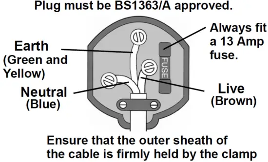
- The BLUE wire must be connected to the terminal which is marked N or colored black.
- The BROWN wire must be connected to the terminal which is marked L or colored red.
- The YELLOW AND GREEN wire must be connected to the terminal which is marked E or ground or colored green.
We strongly recommend that this machine is connected to the mains supply through a Residual Current Device (RCD)
If you are not sure, consult a qualified electrician. DO NOT try to do any repairs.
OPERATION
WARNING: DO NOT USE THIS HEATER IN SMALL ROOMS WHEN THEY ARE OCCUPIED BY PERSONS NOT CAPABLE OF LEAVING THE ROOM ON THEIR OWN, UNLESS CONSTANT SUPERVISION IS PROVIDED.
CAUTION: SOME PARTS OF THIS PRODUCT CAN BECOME VERY HOT AND CAUSE BURNS. PARTICULAR ATTENTION HAS TO BE GIVEN WHERE CHILDREN AND VULNERABLE PEOPLE ARE PRESENT.
- Put the heater in a level position on a flat surface and at a safe distance from flammable materials. Keep a minimum of 2m clearance all round.
- Connect the heater to a suitable power supply.
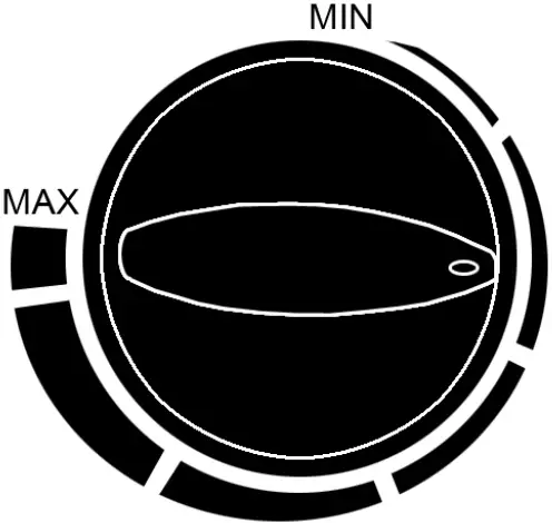
- Set the thermostat control to the maximum setting (fully clockwise).

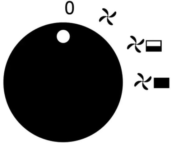
- Set the mode selector to one of the 3 settings:


Off 
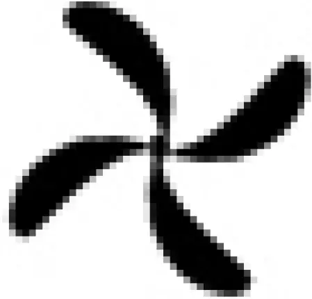
Fan Only 
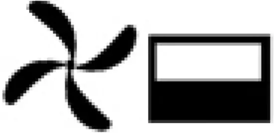
Fan + Heat Setting 1 
Fan + Heat Setting 2 - The heater will take up to three minutes to reach optimum temperature.
- Once the room reaches the required temperature, turn the thermostat control slowly counter-clockwise until the thermostat clicks, leave the control in this position.
- The room temperature will be maintained at this setting. The heater will continue to operate until the power switch is turned to the OFF position.
- For fan only operation, turn the power switch to the fan only setting and set the thermostat to its minimum setting.
- When not in use, disconnect the heater from the mains supply. Store it in a safe, dry, childproof location.

ADJUSTING THE ANGLE
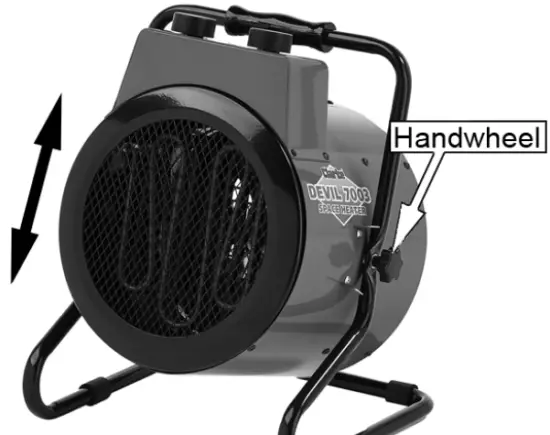
- Loosen both handwheels.
- Adjust to the the required angle.
- Retighten the handwheels.
SAFETY SYSTEMS
THERMOSTATIC PROTECTION
The Devil 7003 has a thermal cut out to prevent the unit from overheating.
If the temperature of the front grille gets too high the thermal cutout will turn off the heating elements. When the fan has cooled the unit sufficiently, normal operation will resume.
MAINTENANCE
WARNING: ALWAYS DISCONNECT FROM THE POWER SUPPLY AND ALLOW THE HEATER IT TO COOL DOWN BEFORE PERFORMING ANY MAINTENANCE TASKS.
- Clean the heater with a soft damp cloth, Do not use solvents or abrasives.
- Make sure that the heater grill is not blocked.
- No other maintenance is required, should you discover any problem with the heater, return it to the Clarke service department for repair.
SPECIFICATIONS
| Operating Voltage and Frequency: (V/Hz) | 230 V / 50Hz |
| Operating Temperature: (Min/Max) (°C): | 0-40°C |
| Heat Output: (kW): | 3 kW |
| Air Output: (m3/h) | 400m3/h |
| Safety Device: | Thermal cut-out / Tip over switch |
| Duty Cycle Classification: | S1 Continuous duty |
| Electrical Insulation Class | I |
| Product: Depth x Width x Height | 302 x 334 x 390 mm |
| Product Weight | 5.6 kg |
TROUBLE SHOOTING
| Problem | Possible Cause | Remedy |
| Heater does not operate, although plugged in with the switch and thermostat switched on. | Plug is loose/bad connection. | Pull the plug out & check the connection of the plug and socket. |
| Fuse blown or circuit breaker trips. | Replace if necessary and investigate cause. If fuse blows repeatedly, consult your Clarke dealer. | |
| No power at socket outlet | Insert the plug in a functioning socket | |
| Heating element glowing hot. | Input voltage too high. | Use a power supply in accordance with the rating on the label. |
| Air inlet grille is blocked | Ensure the heater is kept away from any objects which could cover the air inlet or be drawn into it. | |
| The unit has failed to heat up so only the air fan has operated. | Control switch not set at a “HEATING” level. | Turn switch to a heating level. |
| Thermostat has tripped. | Turn the thermostat and listen. If there is no CLICK and the thermostat is not damaged, the heater will automatically switch ON when it has cooled down. | |
| Abnormal noise. | Heater is not level. | Stand heater on a level surface |
PARTS DIAGRAM
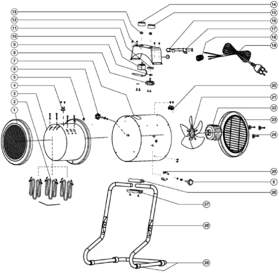
PARTS LIST
| 1 | Front Grille | 16 | Tilt Over Switch |
| 2 | Heating Elements | 17 | Fix Part For Tilt Switch |
| 3 | Chassis Panel | 18 | Supply Cable Entry |
| 4 | Thermal Cut Out | 19 | Power Cable |
| 5 | Bush | 20 | Retaining Clips |
| 6 | Adjustable Knob | 21 | Fan |
| 7 | House Casing | 22 | Motor |
| 8 | Speed Controller | 23 | Rear Grille |
| 9 | Location Part For Switch | 24 | Securing Plate |
| 10 | Temperature Controller | 25 | Spacer |
| 11 | Securing Rings | 26 | Plastic Handle Upper |
| 12 | Control Box | 27 | Plastic Handle Bottom |
| 13 | Fasten Spring | 28 | Frame Handle |
| 14 | Thermostat Knob | 29 | Foot Sleeve |
| 15 | Switch Knob | 30 | Screws |
Part number = (CXDEV7003 + the number of the part)


