![]()
US INDUCTIVE MODULE US-INDS100 OPERATION DESCRIPTION
AND USER MANUAL
A wireless inductive data link for digital data transmission above and underwater
REVISION 1.0 – April 2018 T.Toivola
REVISION 2.0 – April 2020 T.Toivola (RF power, gain, and duty cycle added)
REVISION 3.0 – June 2020 T.Toivola (Chapter 9, No RX only mode)
REVISION 4.0 – July 2020 P.Arvonen (Chapter 10)
The object of the Document
This document contains a description of the functional operation of the UWIS Inductive module and the user manual.
Features
Nominal features for UWIS UWIS-INDS100 inductive link are as follows:
- The device implements the current UWC protocol specification
- The communication range is 1.5 meters minimum
- The frame error rate is less than 1% at a 1.0-meter range
- There is no interference to another UWC device
- The device accepts typical outside interference while maintaining communication range and frame error rate specifications
Operating frequencies
Divisors using an 8 MHz peripheral clock (PERCLK) are shown in
Table 1 with operating frequencies.
Table 1 Operating frequencies.
| TXFREQ | Transmit carrier frequency | 123076.92 Hz | PACK / 65 |
| TXPEAKPOWER | Transmit peak power | 25 dBm | |
| TXDUTYCYCLE | Transmit duty cycle | 20 ms / 1000ms | |
| ANTENNA GAIN | Integral coil antenna gain | 2.15 dBi max | |
| BITRATE | Bit rate | 8791.21 Hz | TXFREQ / 14 |
| SAMPLERATE | Receiver Sample Rate | 43956.04 Hz | PACK/182 |
| RXFREQ | Receive carrier frequency | 123076.92 Hz | |
| RS232 | Serial data bit rate | 115200 baud |
Modulation
The UWC inductive link uses binary phase-shift keying (BPSK) modulation. The BPSK modulation works by shifting the phase of the transmit carrier by 180 degrees for every transmitted bit that is zero. When the transmit bit is one, the carrier is transmitted without change. The bandwidth used is roughly equal to the bit rate.
Host interface
The inductive module is connected to the host with a 7-pin interface cable.
Table 2 Host interface
| Pin | Name | Signal | Value |
| 1 | 3V | 3V regulated supply | 3V +-5% |
| 2 | USERS | RS232 serial bus TX | 115200 baud 8N2 0/3V |
| 3 | USOTX | RS232 serial bus TX | 115200 baud 8N2 0/3V |
| 4 | GND | Ground | |
| 5 | Mute | Mute control to switch off TX | 0/3V control line |
| 6 | – | Reserved | |
| 7 | 12V | 12V regulated supply | 12V +-5% |
MCU
MCU EMF32G210 converts serial data to inductive TX-signal and receives inductive RX-signal converting it to serial data. MCU runs with a 16MHz clock generating needed frequencies according to embedded firmware.
TX amplifier
MCU gives digital timing and modulation for the external mux. Mux gives modulated digital output for transmitter output amplifier. The Digital signal is then filtered to an analog signal with the needed bandwidth. Analog signal is possible to mute with host mute signal to avoid known collisions. Analog amplifier feeds output coil.
The output coil is tuned to 123 kHz to achieve the needed range.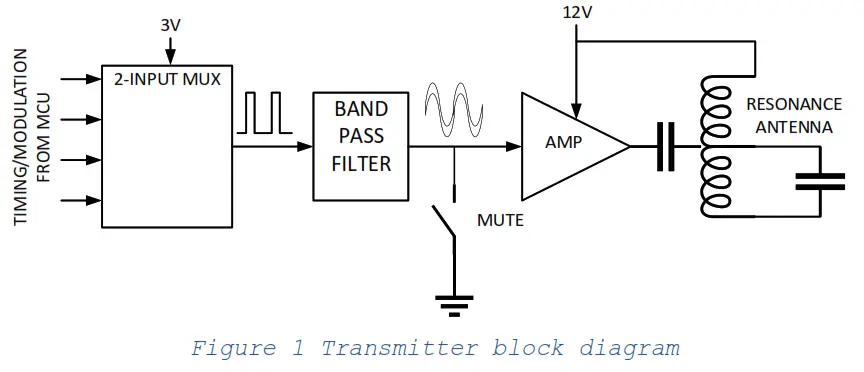
RX amplifier
The receiver coil is tuned to max receiver sensitivity. A low noise amplifier amplifies the received signal for MCU ADC conversion. MCU receives differential signals for BPSK detection. There is no RX-only function mode on this device, TX is always functional and so the receive-only mode cannot be measured.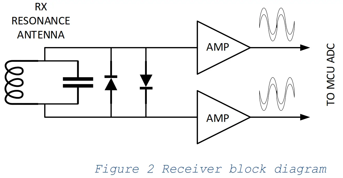
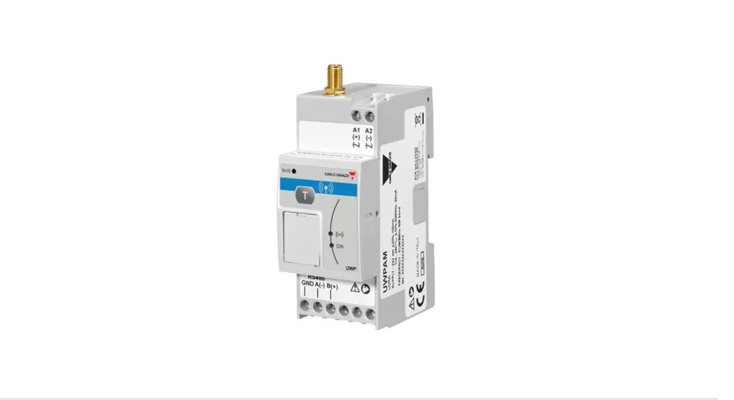
Module usage position
The inductive module is located inside the host enclosure to achieve mechanical, moisture or ESD protection. Host devise nominal location and direction give an optimal range for the inductive antenna.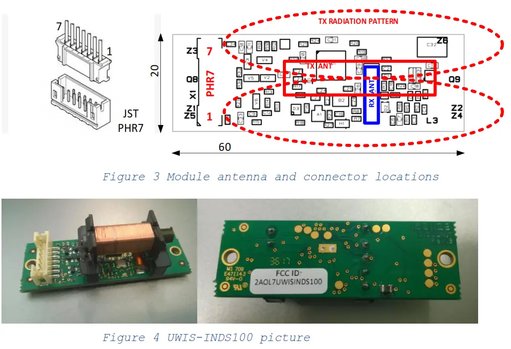
FCC Statement
This device complies with part 15 of the FCC Rules. Operation is subject to the following two conditions:
(1) This device may not cause harmful interference, and (2) this device must accept any interference received, including interference that may cause undesired operation. Changes or modifications not expressly approved by the party responsible for compliance could void the user’s authority to operate the equipment.
UWIS Oy, Kaarinantie 700
20540 Turku, Finland
[email protected]
+358 40 514 0565
www.uwis.fi


