Emaux GLOW+LED Strip Light
PRODUCT INTRO DUCTIN
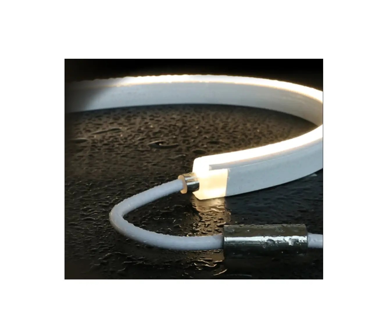
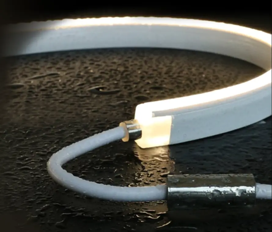
The underwater LED strip is designed for to latest waterproof technologies in IP68. It is an extendable and top view bendable LED light strip tube with a 120-degree beam angle and flat rectangular emission for creating underwater profile lighting.
It can be controlled by a manual or wireless remote dimmer for lighting effect tuning. The LED strip includes arrange of white CCT from 2700K/3000K/3500K/4000K/4500K/5000K/5700K/6500K. To provide a long-life span, reinforced PVC material can resist the harm from UV, saltwater, flame solvents, and dirt, etc. There are seven type of wiring connectors are providing mounting flexibility for layout connections.
SPECIFICATION
ELECTRICAL
Operation Voltage Range: DC24V
Max Power Rating/meter: 10W
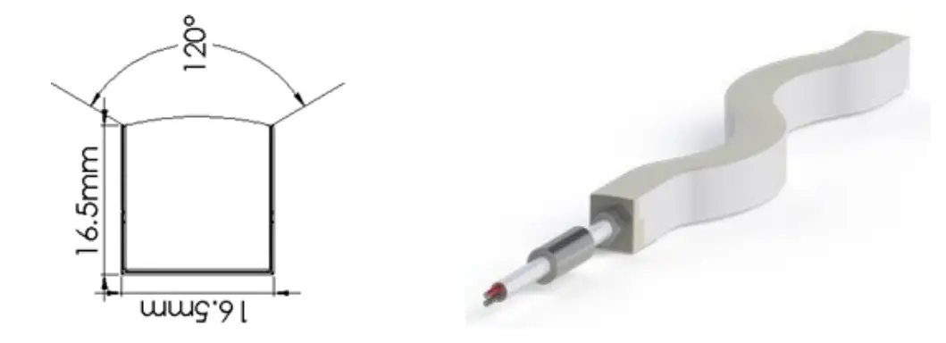
Bean angle: Top view 120 degree
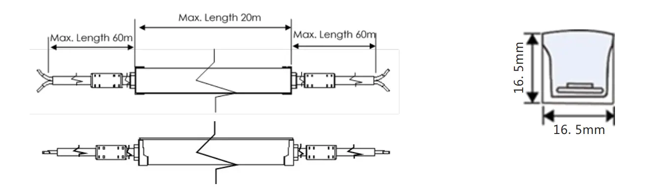
DIMENSIONS (mm)
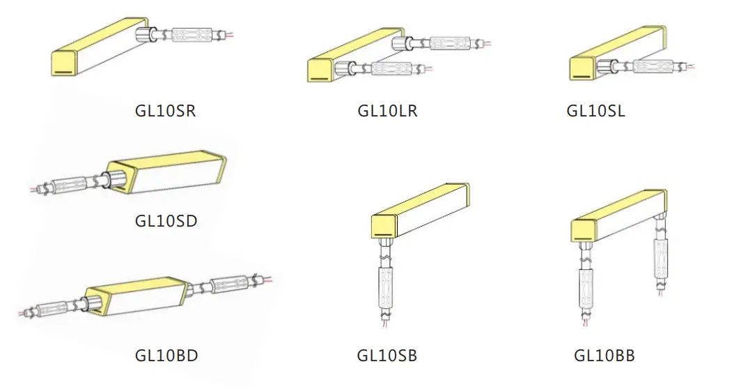
WIRING CONNECTOR TYPE AND PART NUMBER
| CODE | Model | Description |
| 9042915 | GL10 | LED strip max 20m length |
| 9042901 | GL10SR | Power connector side right |
| 9042903 | GL10SL | Power connector side left |
| 9042905 | GL10LR | Power connector side both |
| 9042907 | GL10SD | Power connector side direct |
| 9042909 | GL10BD | Power connector side both direct |
| 9042911 | GL10SB | Power connector side bottom |
| 9042913 | GL10BB | Power connector side both bottom |
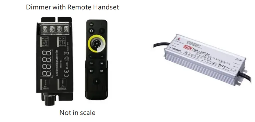
POWER SUPPLY AND DIMMER
24V DC power supply provides LED strip power source and dimmer with remote control to adjust the brightness of the strip
| Code | Mode | Description |
| E042901 | Dimmer Controller | LED Dimmer with remote |
| 106328534 | Power Supply HLG-240H-24 | 24V, 240W, 100-240V AC 50/60Hz input voltage, IP67 |
| 106328535 | Power Supply HLG-120H-24 | 24V, 120W, 100-240V AC 50/60Hz input voltage, IP67 |
DESIGN EXAMPLE
Design a regular shape 10x20m rectangle pool in 3000K color temperature.
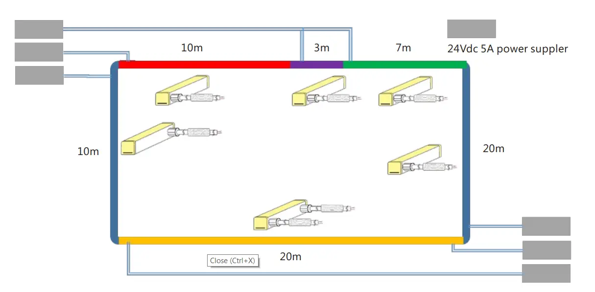
Order details for side power connection cable
| Code | Description | length(m) | Quantity |
| 9042915 + 9042901 | GL10, 10m, color temp 3000K, GL10SR connector side right | 10 | 2 |
| 9042915 + 9042901 | GL10, 3m, color temp 3000K, GL10SR connector side right | 3 | 1 |
| 9042915 + 9042901 | GL10, 7m, color temp 3000K, GL10SR connector side right | 7 | 1 |
| 9042915 +9042903 | GL10, 10m, color temp 3000K, GL10SL connector side left | 10 | 1 |
| 9042915 + 9042905 | GL10, 20m, color temp 3000, GL10LR, connector side both | 20 | 1 |
| 105328534 | 24V 5A power supply | 6 |
To configure the connector orientation for better installation convenience, change the connector model to GL10BD for both side straight connector and GL10SD for single end straight connector.
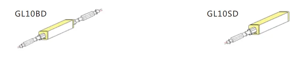
| Code | Description | length(m) | Quantity |
| 9042915 + 9042909 | 10m, color temp 3000K, power connector both side direct | 10 | 3 |
| 9042915 + 9042907 | 3m, color temp 3000K, power connector side direct | 3 | 1 |
| 9042915 + 9042907 | 7m, color temp 3000K, power connector side direct | 7 | 1 |
| 9042915 + 9042909 | 10m, color temp 3000K, power connector both side direct | 20 | 1 |
| 105328534 | 24V 5A power supply | 6 |
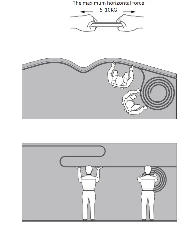
MOUNTING
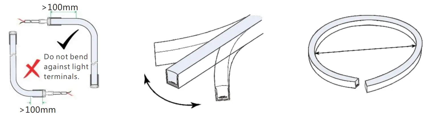
- Installing the Glow+ LED stripe required at least 2 people. Make sure the bending radius is not exceeded while installation. Maximum horizontal force not exceed 10KG

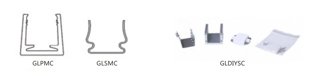
- Mounting clip There are 3 different length of plastic mounting accessories to fit into the mounting and one stainless steel for corner mounting reinforcement.
| Code | Mode | Description |
| 106090026 | GLPMC | Plastic Mounting Clips Transparent 35mm |
| 106090027 | GLPMC1M | Plastic Mounting Channel Transparent 1m |
| 106090028 | GLSMC | Stainless steel Mounting Clip 5cm |
| 106090029 | GLDIYSC | DIY End Connector Kit |
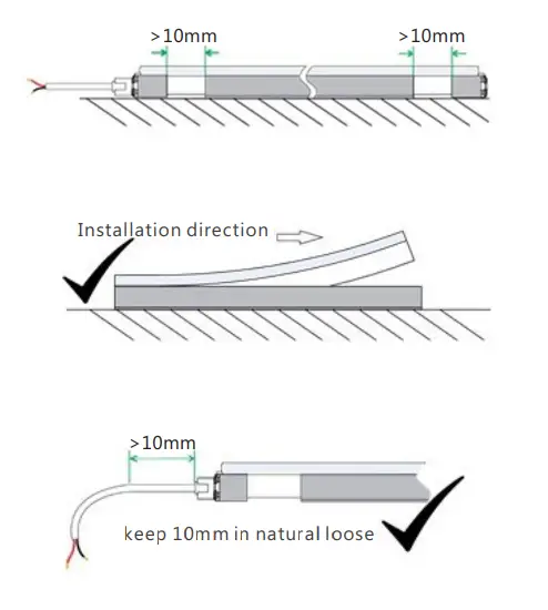
Good mounting example
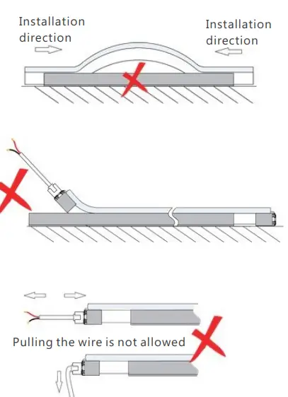
Bad mounting example
Bending
Mount the cable junction in waterproof junction box when apply to outdoor mounting.
ELECTRICAL INSTALLATION
The system operation is 24Vdc only and current rating is 5A per 10 m strips. Therefore, a 120W minimum power supply is required to turn on the light in full brightness.
| Rated power | 120W | 240W |
| LED Strip length | 9.5m | 19m |
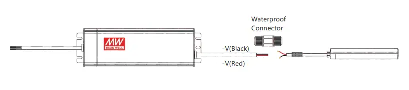
Locate the power supply nearby the LED strip and connect the terminal wiring. The recommended distance is as below table.
| Watts of light | 18AWG 0.82mm² | 17AWG 1.04mm² | 16AW 1.38mm² | 14AWG 2.07mm² | 12AWG 3.29mm² | 10AW 5.62mm² |
| 120W | 2m | 2.5m | 3m | 4m | 8m | 12m |
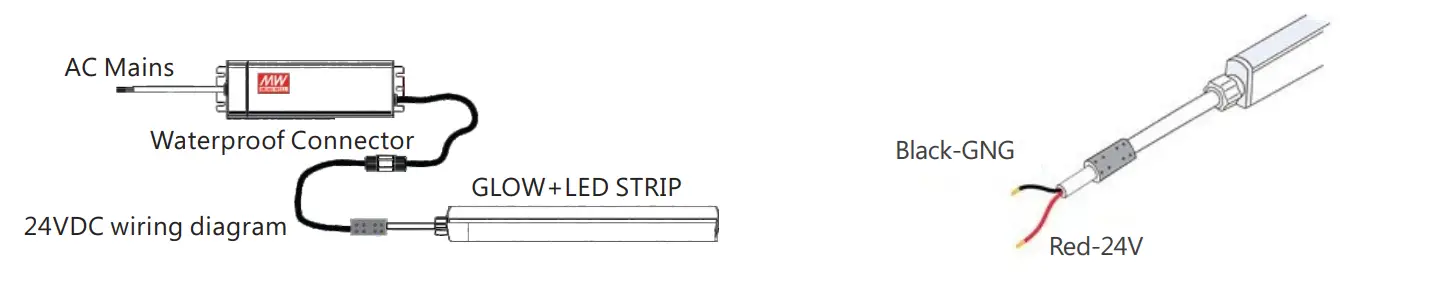
- Connect the Red wiring of LED strip to Red wire of Power Supply.

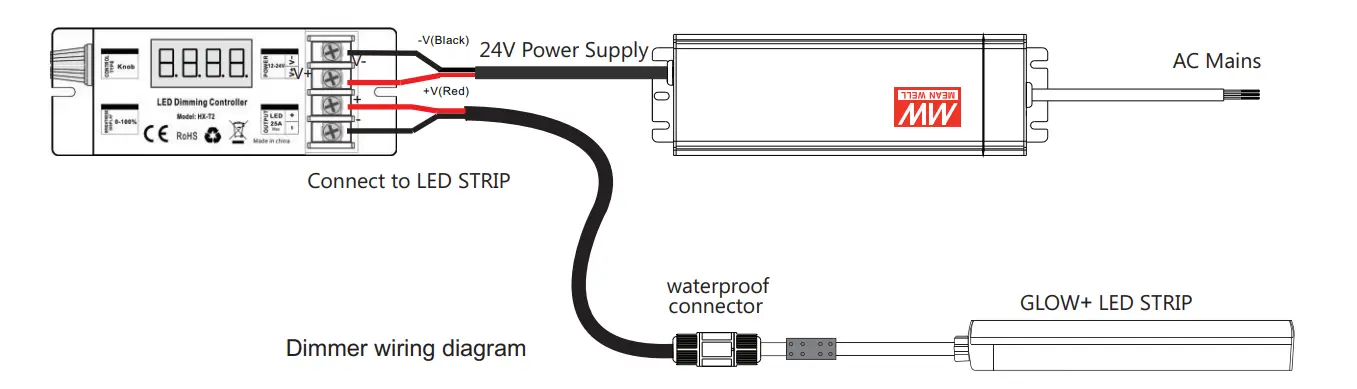
- Wiring diagram with dimmer.

HOW TO USE GLDIYSC TO CUT THE STRIP AND END CAP ASSEMBLE
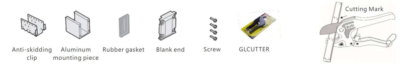
If it is necessary to cut the LED strip to fit into the layout, use the GLCUTTER to cut the length where marked for the “Dotted Line” or “Scissor Mark”. The cut section must have the appropriate IP rated cap flex accessory to maintain water proof IP ratings. Follow the steps below for end cap assemble after cutting.
Step 1 – Place the anti-skidding clip on the very end of the tubing with the 2 tiny tabs that are pointing inwards still touching the end of the material and crimp in place.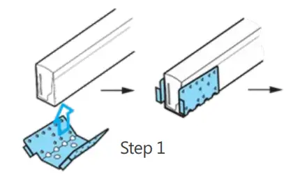
Step 2 – Line up the aluminum mounting piece so the screw hole face the plug and slide on over theantiskidding clip.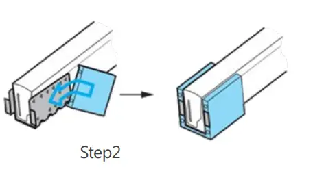
Step 3 – Apply 100% clear silicone onto the end face of led neon flex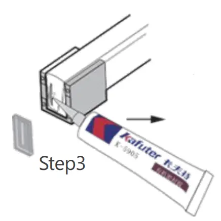
Step 4 – Place the rubber gasket squarely onto the end face of led neon flex.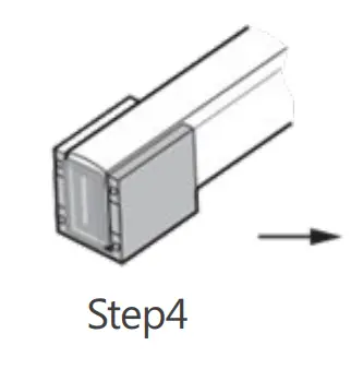
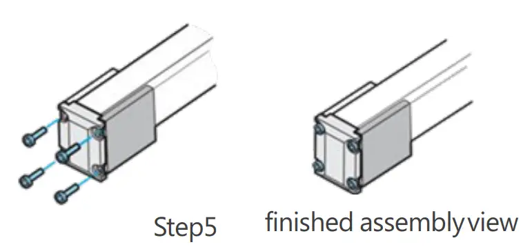
Step 5 – Screw the blank end to the aluminum mounting piece.
| Code | Model | Description |
| 106090030 | GLCUTTER | LED Neon Cutter |