REGIN RCFD-230C Fan Coil Room Thermostat
Safety Precautions
![]() Note! More information about the product can be found in the manual, which is available for download from www.regincontrols.com
Note! More information about the product can be found in the manual, which is available for download from www.regincontrols.com
![]() Caution! Read and understand the instruction before using the product.
Caution! Read and understand the instruction before using the product.
![]() Caution! Ensure that the installation complies with local safety regulations.
Caution! Ensure that the installation complies with local safety regulations.
 Warning! Before installation or maintenance, the power supply must first be disconnected in order to prevent potentially lethal electric shocks! Installation or maintenance of this unit should only be carried out by qualified personnel. The manufacturer is not responsible for any eventual damage or injury caused by inadequate skills during installation, or through removal of or deactivation of any security devices.
Function
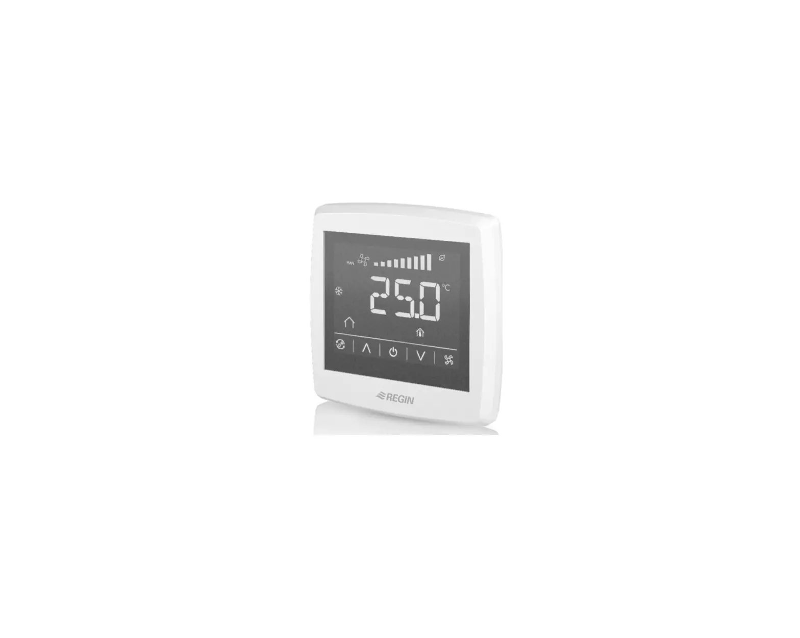
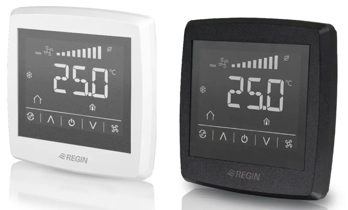
The room thermostat regulates the heating and/or cooling in a room via on/off outputs for 2- or 4 pipe installations, and has a function for three speed fan control. The large LCD touch screen displays status and is also used to access all parameters, such as setpoint, hysteresis, fan speed etc.
The unit has a built-in temperature sensor for controlling the room temperature. The change-over function can be controlled using an external PT1000 sensor or via a digital input connected to any potential free contact. Functions such as mould protection and automatic valve exercise ensures a proper functionality and a problem free installation over time.
Technical Data
| Supply voltage | 230 V ~ (207…253 V ~ 50/60 Hz) |
| Power consumption | < 2 VA |
| Protection class | IP30 |
| Ambient humidity | 10…90 %RH (non-condensing) |
| Ambient temperature | 0…50 °C |
| Measuring range, temperature | 0…50 °C |
| Sensor element, temperature | NTC |
| Accuracy, temperature | ±0.5 K |
| Display | Built-in |
| Display type | LED-backlit LCD |
| Output signal, temperature | NTC |
| Setpoint adjustment | 5…35 °C |
| Mounting | Room (flush-mounted with screw dis- tance cc 60 mm) |
| Installation | Fan-coils, 2- or 4-pipe |
| Digital inputs (DI) | 1 x Closing potential-free contact |
| Digital outputs (DO) | 3 x Relay outputs for 3-step fan control, 230 V AC, Max. 5 A 2 x Relay outputs for On/Off valve actuators, 230 V AC, Max. 5 A |
| Analogue inputs (AI) | 1 x PT1000 |
| Change-over function | Automatic |
| Communication port | 1 |
| Internal serial port, type | RS485 |
| Internal serial port, built-in protocol | Modbus (RTU) |
| Internal serial port, communication speed | 9600 bps (4800…38400 bps) |
| Internal serial port, parity | Even (Even, Odd, None) |
| Internal serial port, stop bit | 1 (1 or 2) |
| Cable connection | Screw terminals max. 1.5 mm2 (AWG 16) |
| Dimensions, external (WxHxD) | 95 x 95 x 50.5 mm |
Installation
- Separate the back plate from the display part with a small screw driver. Insert the screw driver in the grooves at the bottom of the unit.
- Connect the wires to the terminals.
- Place the back plate over the electrical wallbox and fasten it on the wall using the mounting holes.
- Clip the display back onto the back plate.
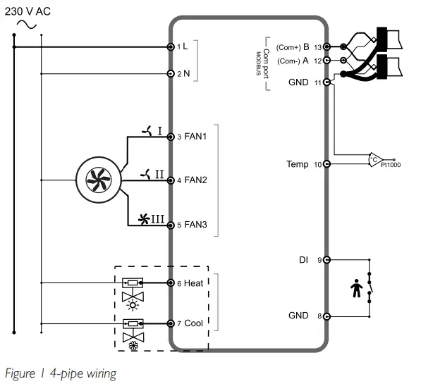
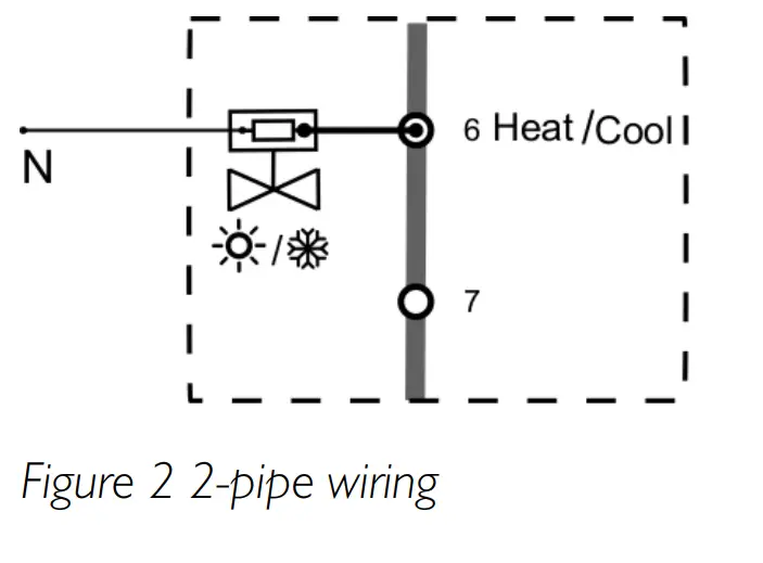
Wiring
| Terminal | Description |
| L | Supply voltage |
| N | Supply voltage |
| FAN1 | 230 V AC Relay 1 |
| FAN2 | 230 V AC Relay 2 |
| FAN3 | 230 V AC Relay 3 |
| Heat | 230 V AC Relay 4 |
| Cool | 230 V AC Relay 5 |
| GND | GND (for DI) |
| DI | Digital input for presence detection, hotel key card etc |
| Temp | Analogue input for external PT1000 sensor, change-over |
| GND | Agnd for terminal Temp Serial communication port, Com N |
| A | Serial communication port, Com A |
| B | Serial communication port, Com B |
Settings
The thermostat settings can be controlled in one of the following ways:
- Display buttons: user settings such as temperature setpoint adjustment and fan speed
- Parameter list: quick configurations for installer
- Modbus variables: advanced thermostat control via Modbus communication
The parameter list is entered by pressing the Arrow up and Arrow down buttons in the display simultaneously for five seconds.
Table 1 Buttons available in the display
| Symbol | Description |
 | Changeover button to switch between heating and cooling via the display |
 | Arrow up/Increase button |
 | On/Off button |
 | Arrow down/Decrease button |
 | Fan button to regulate the fan speed via the display |
![]() Note! All parameters and variables are listed in the manual.
Note! All parameters and variables are listed in the manual.
Handling
The display behaves differently depending on the mode and the state that the thermostat is currently operating in.
The thermostat can be in one of the following states:
- Off: Energy saving state where the thermostat neither heats nor cools. No background light is lit, only the On/Off button is shown.
- Standby: Energy saving state where reduced heating or cooling takes place.
- Occupied: Comfort state when someone is present in the room. Optimal heating and cooling takes place.
The thermostat can be in three different modes when in Standby or Occupied state:
- Idle mode: The thermostat has been inactive during a set time span.
All buttons and segments, except the two arrows, are dimmed down in the display. - Active mode: The thermostat is activated, but no changes are made.
The display shows either the calculated setpoint or the current room temperature. - Setpoint mode: This mode is activated when pressing one of the arrows when in Active mode. Either the calculated setpoint or the current user defined setpoint adjustment are shown.
Customers Support

This product carries the CE-mark. More information is available at www.regincontrols.com.
Contact
AB Regin, Box 116, 428 22 Kållered, Sweden
Tel: +46 31 720 02 00, Fax: +46 31 720 02 50
www.regincontrols.com, [email protected]