![]()
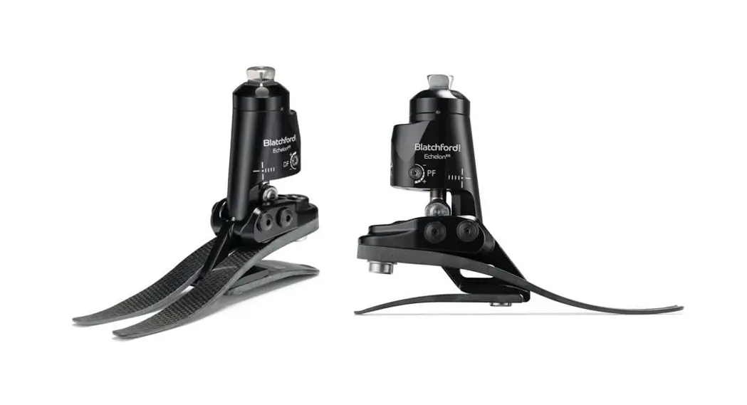
 Echelon VAC
Instructions for Use
EVAC22L1S—EVAC30R8S
EVAC22L1SD—EVAC30R8SD
Instructions for Use
Description and Intended Purpose
These instructions are for use by the practitioner.
The term device is used throughout this document to refer to EchelonVAC .
Application
The device is to be used exclusively as part of a lower limb prosthesis.
Intended for single user.
The device provides limited self-alignment of the prosthesis on varied terrain and following footwear changes. It is intended to improve on postural sway and symmetry while easing abnormal pressures at the socket interface. A moderate energy return foot with multi-axial ankle movement. Independent heel and toe springs provides some axial deflection. The split toe provides good ground compliance. In addition to the visco-elastic, self-aligning hydraulic ankle it generates an elevated vacuum in the range 12-17in Hg.
Activity Level
This device is recommended for users that have the potential to achieve Activity Level 3 who may benefit from enhanced stability and an increase in confidence on uneven surfaces. Of course there are exceptions and in our recommendation we want to allow for unique, individual circumstances. There may also be a number of users in the Activity Levels 2 and 4* who would benefit from the enhanced stability offered by the device, but this decision should be made with sound and thorough justification.
Activity Level 1
Has the ability or potential to use a prosthesis for transfers or ambulation on level surfaces at fixed cadence. Typical of the limited and unlimited household ambulator.
Activity Level 2
Has the ability or potential for ambulation with the ability to traverse low-level environmental barriers such as curbs, stairs, or uneven surfaces. Typical of the limited community ambulator.
Activity Level 3
Has the ability or potential for ambulation with variable cadence. Typical of the community ambulator who has the ability to traverse most environmental barriers and may have vocational, therapeutic, or exercise activity that demands prosthetic utilization beyond simple locomotion.
Activity Level 4
Has the ability or potential for prosthetic ambulation that exceeds basic ambulation skills, exhibiting high impact, stress, or energy levels. Typical of the prosthetic demands of the child, active adult, or athlete.
*(maximum user weight 100 kg (220 lb) and always use one higher spring rate category than shown in the Spring Set Selection table).
Clinical Benefits
- Increased ground clearance reduces risk of trips and falls
- Improved balance through self-alignment
- Improved ground compliance for slope negotiation
- Healthier residual limb tissue and skin
- Reduction in residual limb volume fluctuations
- Reduced loading on the residual limb
- Improved kinetic gait symmetry
- Improved wound management
- Decreased pistoning
- Increased walking speed
Contraindications
This device may not be suitable for Activity Level 1 individuals or for competitive sports events, as these types of users will be better served by a specially designed prosthesis optimized for their needs.
It may not be suitable for use on individuals with poor balance , especially for bilateral use. If the user has any pertinent circulation condition seek medical advice if there is a possible risk of adverse reactions.
It is NOT recommended for use for:
- Wearers with poor cognitive function
- Users on dialysis
- Users with neuromas preventing weight bearing
- Use where a large range of heel height is required without re-alignment
The device should only be fitted by suitably trained practitioners and should only be used with suitable, well fitting total contact sockets. There should be no reliefs or voids into which tissue may be drawn by the vacuum.
- If multiple walled sockets are used there should be no voids in their construction
- There should be no excessive flares to socket brim or trim lines Ensure that the user has understood all instructions for use, drawing particular attention to the section regarding Maintenance.
Spring Set Selection
Activity Level 3
44-52 53-59 60-68 69-77 78-88 89-100 101-116 117-125 kg User Weight
(100-115) (116-130) (131-150) (151-170) (171-195) (196-220) (221-255) (256-275) (lbs)
1 2 3 4 5 6 7 8 Foot Spring Set
Note:
If in doubt choosing between two categories, choose the higher rate spring set.
Foot Spring set recommendations shown are for transtibial users.
For transfemoral users we suggest selecting a spring set one category lower, refer to Section 8 Fitting Advice to ensure satisfactory function and range of movement.
Safety Information
![]() This warning symbol highlights important safety information which must be followed carefully.
This warning symbol highlights important safety information which must be followed carefully.![]() Any changes in the performance or function of the limb e.g. restricted movement, non-smooth motion or unusual noises should be immediately reported to your service provider.
Any changes in the performance or function of the limb e.g. restricted movement, non-smooth motion or unusual noises should be immediately reported to your service provider.![]() Always use a hand rail when descending stairs and at any other time if available.
Always use a hand rail when descending stairs and at any other time if available.![]() The device is not suitable for extreme sports, running or cycle racing, ice and snow sports, extreme slopes and steps. Any such activities undertaken are done so completely at the users’ own risk. Recreational cycling is acceptable.
The device is not suitable for extreme sports, running or cycle racing, ice and snow sports, extreme slopes and steps. Any such activities undertaken are done so completely at the users’ own risk. Recreational cycling is acceptable.![]() Assembly, maintenance and repair of the device must only be carried out by a suitably qualified clinician.
Assembly, maintenance and repair of the device must only be carried out by a suitably qualified clinician.![]() Ensure only suitably retrofitted vehicles are used when driving. All persons are required to observe their respective driving laws when operating motor vehicles.
Ensure only suitably retrofitted vehicles are used when driving. All persons are required to observe their respective driving laws when operating motor vehicles.![]() To minimise the risk of slipping and tripping, appropriate footwear that fits securely onto the footshell must be used at all times.
To minimise the risk of slipping and tripping, appropriate footwear that fits securely onto the footshell must be used at all times.![]() After continuous use the ankle casing may become hot to the touch. Avoid exposure to extreme heat and/ or cold.
After continuous use the ankle casing may become hot to the touch. Avoid exposure to extreme heat and/ or cold.![]() The user must not adjust or tamper with the setup of the device.
The user must not adjust or tamper with the setup of the device.![]() Be aware of finger trap hazard at all times.
Be aware of finger trap hazard at all times.
Construction
Principal Parts
- Hydraulic Body Assembly including pyramid (Aluminium/St. Stl./Titanium)
- Carrier Assembly (Aluminium/St. Stl.)
- Heel & Toe Springs (e-Carbon)
- Spring Attachment Screws (Titanium/St.Stl.)
- Glide Sock (UHM PE)
- Foot Shell (PU)
- Vacuum Parts (PU, Nylon, Aluminium)
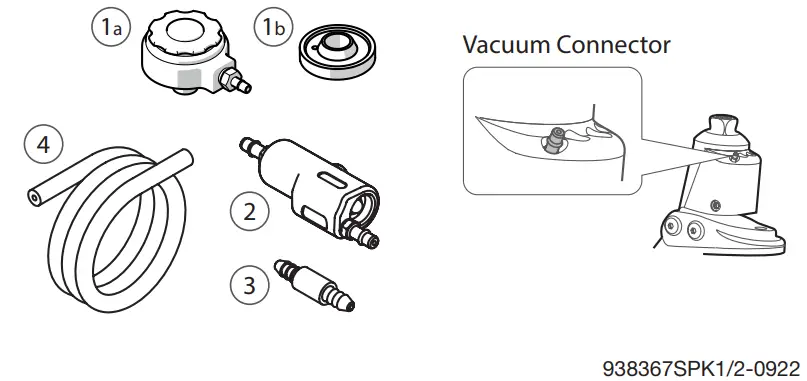
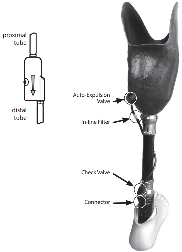
Vacuum System Parts
- a Auto-Expulsion Valve
1b Threaded Housing - Check Valve
- In-line Filter
- Vacuum Tubing
Function
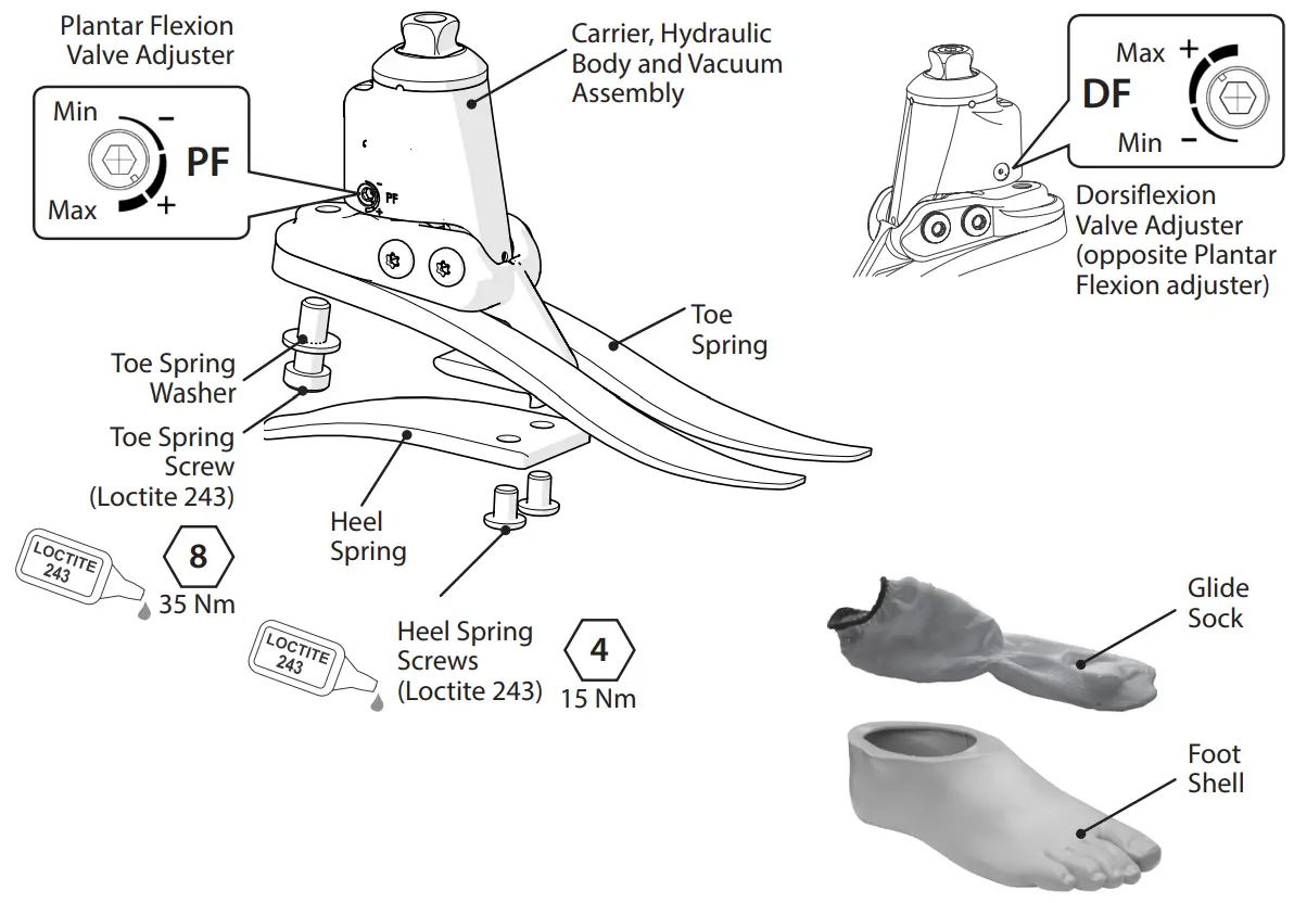
The device comprises a hydraulic body assembly containing adjustable hydraulic valves. The valves can be independently adjusted to increase and reduce hydraulic resistance of plantar flexion and dorsiflexion.
The hydraulic body also houses a pneumatic chamber and piston which, via one-way valves and a filter, creates a vacuum that can be passed via tubing to a prosthetic socket. For maximum vacuum effect the check valve should be positioned close to the ankle. The number of steps necessary to create an elevated vacuum will vary depending on the free space/air in the system. The use of multiple socks may require an increased number of steps to reach an elevated
vacuum.
The hydraulic body assembly is connected to a carrier assembly via two pivot pins. Heel and toe springs are attached to the carrier assembly using titanium and stainless steel screws. The foot is wrapped in a UHM PE sock which is in turn surrounded by a PU foot shell.
Maintenance
Maintenance must be carried out by competent personnel.
It is recommended that the following maintenance is carried out annually:
- Remove the foot shell and glide sock, check for damage or wear and replace if necessary.
- Check all screws for tightness, clean and reassemble as necessary.
- Visually check the heel and toe springs for signs of delamination or wear and replace if necessary. Some surface damage may occur after a period of use, this does not affect the function or strength of the foot.
The wearer should be advised:
Any changes in performance of this device must be reported to the practitioner.
Changes in performance may include: - Increase in ankle stiffness
- Reduced ankle support (free movement)
- Any unusual noise
- Lack of vacuum
The practitioner must also be informed of: - Any changes in body weight and/or activity level.
- Discoloration of the residual limb.
The user should be advised that a regular visual check of the foot is recommended, signs of wear that may affect function should be reported to their service provider (e.g. significant wear or excessive discoloration from long term exposure to UV).
Cleaning
Use a damp cloth and mild soap to clean outside surfaces, do not use aggressive cleansers. NB. if high hydraulic resistances are used such that they restrict ankle movement, the ability to generate vacuum may be compromised.
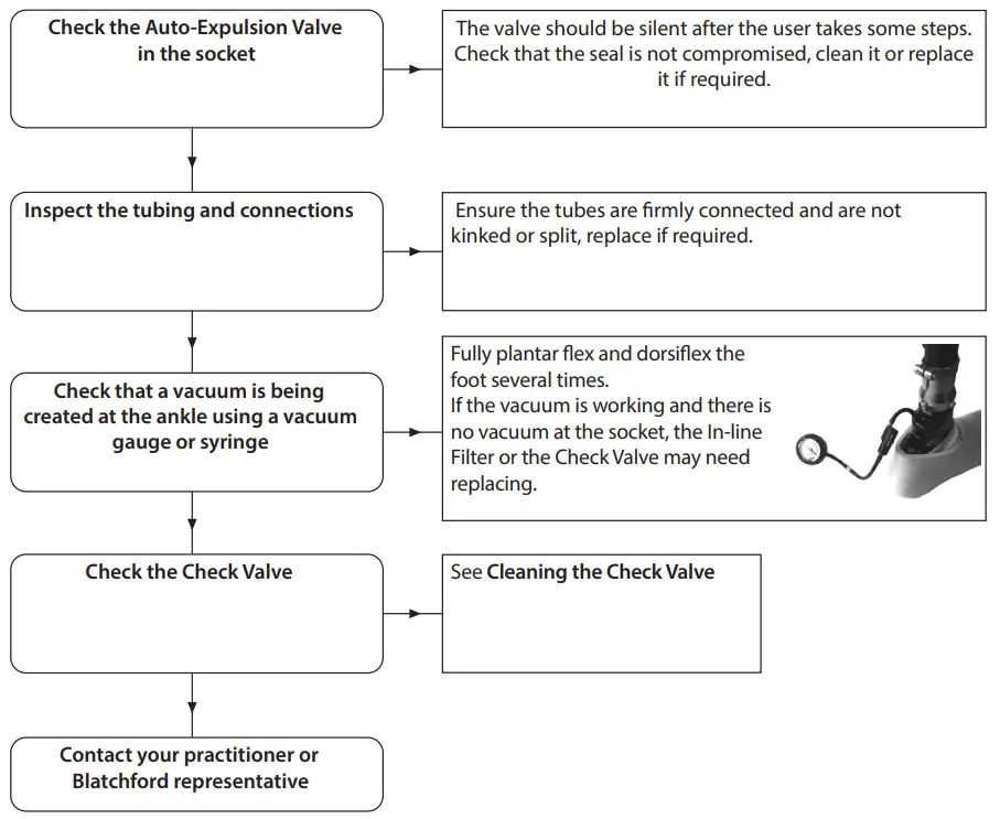
5.1 Vacuum System Maintenance Guide
- Visual Inspection
Make a visual inspection of the system parts paying attention to connections, these must be air tight to ensure integrity of the vacuum. Inspect the tubes and ensure they are firmly connected and are not kinked or split. The socket arrangement should also be inspected to check the integrity of the vacuum seals. - Check Valve
The check valve retains the vacuum created in the socket. It must be connected with the direction arrow pointing towards the ankle.
5.2 Vacuum System Checklist
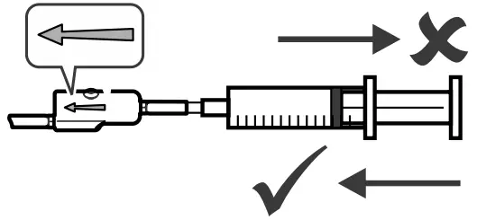
- Cleaning the Check Valve, vacuum inlet
Disconnect the check valve and connect a syringe to the proximal tube with the flow direction arrow pointing away from the syringe. If the valve is working correctly the syringe should only push inwards. If the valve is blocked use the syringe to clear the valve with a ‘blast of air’ (Do not use compressed air). If it is still blocked clean it with distilled water using the syringe. If the valve is still not working replace it (409663 or 409863).
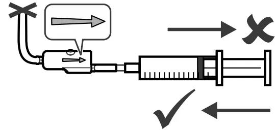
- Cleaning the Check Valve, exhaust port
Check the exhaust valve is working correctly by connecting a syringe to the distal tube and clamp the proximal tube. Use a ‘blast of air’ to clear it through (Do not use compressed air). If the exhaust valve is working correctly and retaining the vacuum it should not be possible to draw the syringe plunger back out again.
Limitations on Use
Intended Life
A local risk assessment should be carried out based upon activity and usage.
Lifting Loads
User weight and activity is governed by the stated limits.
Load carrying by the user should be based on a local risk assessment.
Environment
Avoid exposing the device to corrosive elements such as water, acids and other liquids. Also avoid abrasive environments such as those containing sand for example as these may promote premature wear.
For use only by appropriately trained practitioners.
Should only be used with well fitting total surface bearing sockets with no reliefs or voids, which have been constructed with air tight sockets and a suspension sleeve to create an air tight seal proximally.
Exclusively for use between -15 ˚C and 50 ˚C (5 ˚F to 122 ˚F).
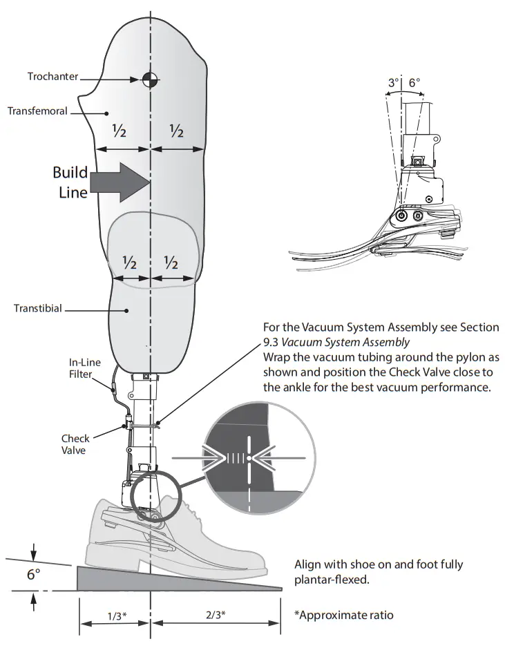
Bench Alignment
7.1 Static Alignment
Align transfemoral devices according to fitting instructions supplied with the knee. Keep the build line between pivots as shown, using shift and/or tilt devices as necessary.
Tilt Setting
Align limb to achieve range of motion shown.
7.2 Biomimetic Alignment
The aim of alignment is to achieve a “balance point” while standing and set the hydraulically damped range of motion. The aim of damping adjustment is to fine tune the ankle-foot rollover stiffness characteristics until a comfortable gait is achieved. Due to the increased range of motion provided by the ankle the user may experience the need for more voluntary control and initially find the ankle disconcerting during setup. This should quickly pass upon completion of satisfactory setup.
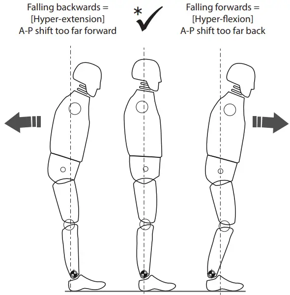 * Ensure that the user is relaxed and not resting on the dorsiflexion limit.
7.3 Biomimetic Adjustment
NB: Carry out static alignment while ensuring the user has some means of support such as parallel bars. This is standing alignment only.
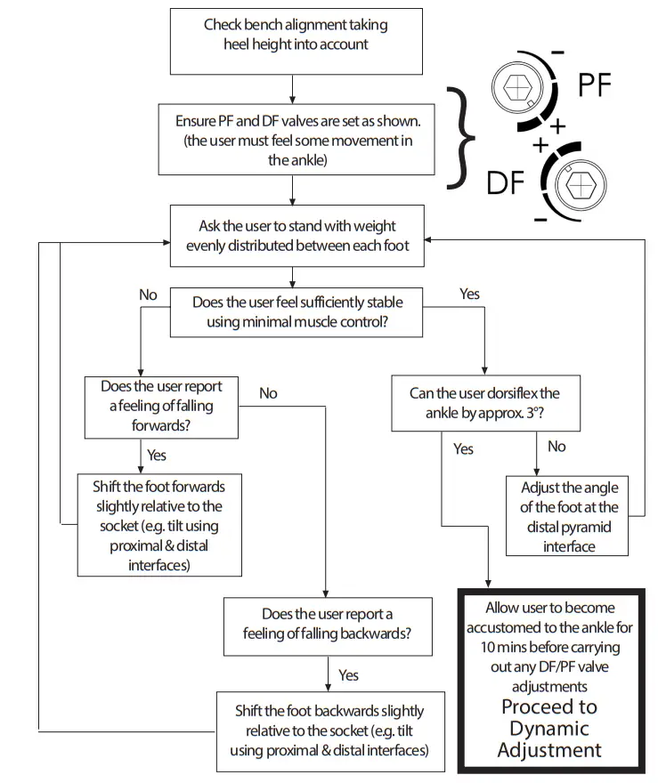
Use shift for static alignment and standing.
The device should encourage some degree of self adjustment to achieve a sense of balance for the user during standing.
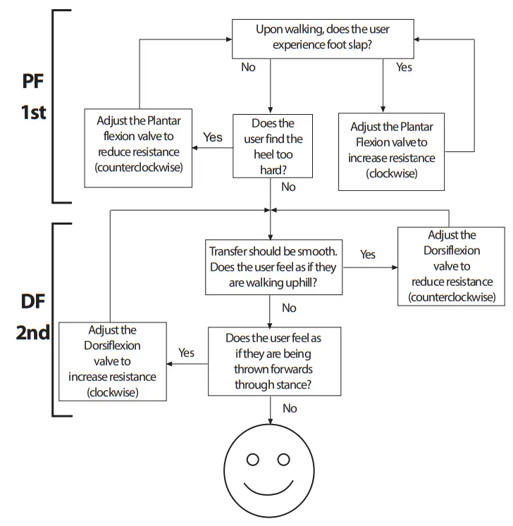
7.4 Dynamic Adjustment
Adjustment of the hydraulic valves
The user should experience the ankle moving smoothly with the body through the gait cycle with no additional effort required by the user to overcome the hydraulic resistance of the ankle.
During this procedure the user should walk at normal speed, in a straight line on a level surface.
Guidance
Following dynamic adjustment, trial the foot/ankle on ramps and stairs. Ensure the user is comfortable with the kind of terrain he/she may normally be expected to encounter. If the user reports any issues with comfort, usability or range of movement of the ankle, adjust accordingly.
Fitting Advice
The correct alignment (A-P position), range of motion (distribution of plantar flexion to dorsiflexion) and adjustment of the hydraulic settings are critical in achieving a smooth roll over and correct slope adaptation (see Section 7.3 Biomimetic Adjustment).
The springs for the device will be supplied assembled with heel and toe springs of the same category. If after following the instructions below you still have problems with the function please contact the sales team in your area for advice.
Any of the following:
- Incorrect spring selection
- Incorrect A-P shift alignment
- Incorrect distribution of plantar flexion and dorsiflexion range will have a negative effect on function and stability. The user should feel the vacuum effect after taking approximately 15-20 steps depending on the initial socket fit.
| Symptoms | Remedy | |
| 1. | Sinking at heel strike Difficulty in achieving a smooth progression to mid stance User feels they are walking up hill or forefoot feels excessively long | 1.Increase plantar flexion resistance 2.Check A-P shift alignment ensure foot is not too anteriorly positioned 3.Check distribution of plantar flexion and dorsiflexion movement; ensure that the plantar flexion range is not excessive 4.Check spring category is not too soft, if so fit a higher rate spring |
| 2. | Progression from heel strike to mid stance is too rapid Difficulty in controlling the energy return from the foot at the heel strike (reduced knee stability) User feels heel is too hard, fore foot is too short | 1.Reduce plantar flexion resistance 2.Check A-P shift alignment ensure foot is not too posteriorly positioned 3.Check distribution of plantar flexion and dorsiflexion movement; ensure that there is adequate plantarflexion range 4.Check the spring category is not too high for the weight and activity of the patient, if so fit lower rate spring |
| 3. | Heel contact and progression feel OK but: Forefoot feels too soft Forefoot feels too short User feels they are walking down hill, possibly with reduced knee stability Lack of energy return | 1.Increase dorsiflexion resistance 2.Check A-P shift alignment ensure foot is not too posteriorly positioned 3.Check distribution of plantar flexion and dorsiflexion movement; ensure that there is not excessive dorsiflexion range 4.Check the spring category is not too soft for the weight and activity of the patient, if so fit higher rate spring |
| 4 | Forefoot feels too rigid Forefoot feels too long Feels like walking up hill | 1. Reduce dorsiflexion resistance 2. Check A-P shift alignment; ensure foot is not too anteriorly positioned 3. Check distribution of plantar flexion and dorsiflexion movement; ensure that there is sufficient dorsiflexion range 4. Check the spring category is not too rigid for the weight and activity of the user, if so fit a lower rate spring |
Vacuum System
| Symptoms | Cause/Remedy | |
| 1. | Unable to generate a vacuum | Vacuum tube(s) split or disconnected Inspect and repair/replace as necessary |
| Check and clean/replace the check valve | ||
| Filter blocked, replace Filter | ||
| Limited ankle movement creating insufficient vacuum due to: 1.Excessive PF/DF setting 2.Footwear | ||
| 2. | Unable to maintain a vacuum | Vacuum tube(s) split or disconnected Inspect and repair/replace as necessary |
| Check and clean/replace the check valve | ||
| Leakage at socket valve/barbs Reseal valve/barb | ||
| Porous socket Seal with lacquer/re-make | ||
| Check the integrity of the vacuum seal at the socket/ residuum interface |
Assembly Instructions
![]() Be aware of finger trap hazard at all times.
Be aware of finger trap hazard at all times.![]() Use appropriate health and safety equipment at all times including extraction facilities.
Use appropriate health and safety equipment at all times including extraction facilities.
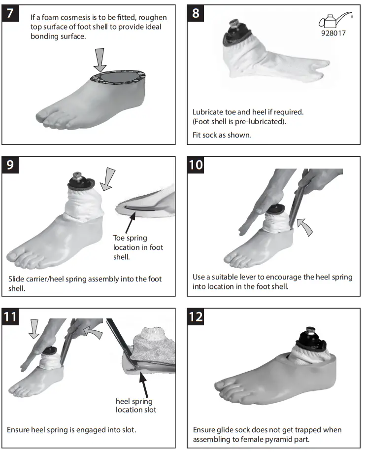
9.1 Footshell removal
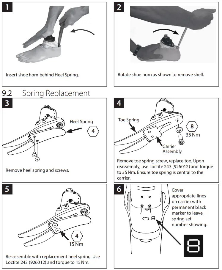
If a cosmetic finish is required please contact a member of the Blatchford Sales Team.
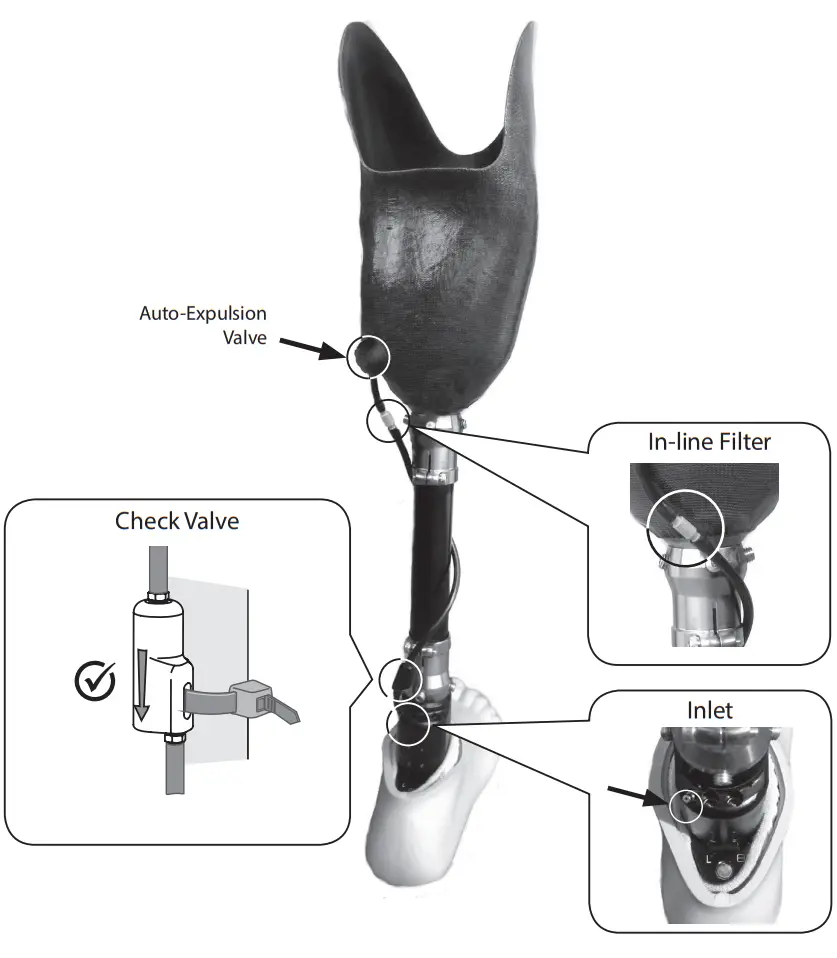
9.3 Vacuum System Assembly
- Push the In-line Filter on to a short piece of vacuum tubing and connect it to the AutoExpulsion Valve.
- Attach a length of vacuum tubing to the In-line Filter and wrap it around the pylon. Connect the other end of the tube to the Check Valve ensuring that the flow arrow points towards the ankle. For maximum vacuum, position the Check Valve close to the inlet on the device. Connect a short length of vacuum tubing from the Check Valve to the inlet on the ankle to complete the vacuum system.
Technical Data
| Operating and Storage Temperature Range: | 15 ˚C to 50 ˚C (5 ˚F to 122 ˚F) |
| Component Weight [Size 26N]: | 930 g (2 lb 1 oz) |
| Recommended Activity Level: | 2, 3, 4 |
| Maximum User Weight: | 125 kg (275 lb) |
| Proximal Alignment Attachment: | Male Pyramid (Blatchford) |
| Range of Hydraulic Ankle Motion: | 6 degrees plantar flexion to 3 degrees dorsiflexion |
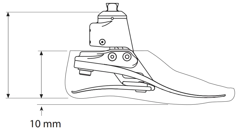
| (excludes additional range of motion provided by heel and toe springs) Build Height: | [Sizes 22-24] 120 mm |
| [See diagram below] Heel Height: | [Sizes 25-26] 125 mm [Sizes 27-30] 130 mm |
| Maximum Vacuum: | 17in Hg |
Fitting length
| Size | A | Size | B |
| 22–24 | 120 mm | 22–26 | 65 mm |
| 25–26 | 125 mm | 27–28 | 70 mm |
| 27–30 | 130 mm | 29–30 | 75 mm |
Ordering Information
Order Example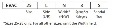 Available from size 22 to size 30:
EVAC22L1S to EVAC30R8S
EVAC22L1SD to EVAC30R8SD (add ‘D’ for a dark tone foot shell)
e.g. EVAC25LN3S, EVAC22R4S, EVAC27RW4SD
| Spring Kits | ||||
| Rate | Foot Sizes | |||
| Small (S) | Medium (M) | Large (L) | Extra Large (XL) | |
| 22-24 | 25-26 | 27-28 | 29-30 | |
| Set 1 | 5398015 | 5398105 | 5398195 | 5398285 |
| Sett | 5398025 | 5398115 | 539820S | 5398295 |
| Set 3 | 5398035 | 5398125 | 539821S | 5398305 |
| Set 4 | 5398045 | 5398135 | 539822S | 5398315 |
| Set 5 | 5398055 | 5398145 | 539823S | 5398325 |
| Set 6 | 5398065 | 5398155 | 539824S | 5398335 |
| Set 7 | 5398075 | 5398165 | 539825S | 5398345 |
| Set 8 | 5398085 | 5398175 | 5398265 | 5398355 |
| Foot Shell (for dark add ‘D’) | ||
| Size/Side | Narrow | Wide |
| 22L | 539038S | – |
| 22R | 539039S | – |
| 23L | 539040S | – |
| 23R | 539041S | – |
| 24L | 539042S | – |
| 24R | 539043S | – |
| 25L | 539044SN | 539044SW |
| 25R | 5390455N | 539045SW |
| 26L | 5390465N | 539046SW |
| 26R | 5390475N | 539047SW |
| 27L | 5390485N | 539048SW |
| 27R | 539049SN | 539049SW |
| 28L | 539050SN | 539050SW |
| 28R | 539051SN | 539051SW |
| 29L | – | 539052S |
| 29R | – | 539053S |
| 30L | – | 539054S |
| 30R | – | 539055S |
| Item | Part. No. |
| Glide Sock (Sizes 22-26) | 531011 |
| Glide Sock (Sizes 27-30) | 532811 |
| DF/PF Adjuster Key, 4.0 A/F Allen | 940236 |
| Vacuum System Parts: | |
| Socket Connection Kit | 409663 |
| Check Valve Service Kit | 409863 |
Liability
The manufacturer recommends using the device only under the specified conditions and for the intended purposes. The device must be maintained according to the instructions for use supplied with the device. The manufacturer is not liable for any adverse outcome caused by any component combinations that were not authorized by them.
CE Conformity
This product meets the requirements of the European Regulation EU 2017/745 for medical devices. This product has been classified as a class I device according to the classification rules outlined in Annex VIII of the regulation. The EU declaration of conformity certificate is available at the following internet address: www.blatchford.co.uk

Compatibility
Combination with Blatchford branded products is approved based on testing in accordance with relevant standards and the MDR including structural test, dimensional compatibility and monitored field performance.
Combination with alternative CE marked products must be carried out in view of a documented local risk assessment carried out by a Practitioner.
Warranty
This device is warranted for 36 months – foot shell 12 months – glide sock 3 months.
This warranty does not apply to:
Consumable parts including the vacuum tubing, in-line filter and valves unless a failure has occurred due to a defect in materials or workmanship. The user should be aware that changes or modifications not expressly approved could void the warranty, operating licenses and exemptions. See Blatchford website for the current full warranty statement.
Reporting of Serious Incidents
In the unlikely event of a serious incident occurring in relation to this device it should be reported to the manufacturer and your national competent authority.
Environmental Aspects
Where possible the components should be recycled in accordance with local waste handling regulations.
Retaining the Packaging Label
You are advised to keep the packaging label as a record of the device supplied.
Trademark Acknowledgements
Echelon and Blatchford are registered trademarks of Blatchford Products Limited.
Manufacturer’s Registered Address![]() Blatchford Products Limited, Lister Road, Basingstoke RG22 4AH, UK.
Blatchford Products Limited, Lister Road, Basingstoke RG22 4AH, UK.
938367SPK1/2-0922
blatchford.co.uk/distributors
| Blatchford Products Ltd. Unit D Antura Kingsland Business Park Basingstoke RG24 8PZ UNITED KINGDOM Tel: +44 (0) 1256 316600 Fax: +44 (0) 1256 316710 Email: [email protected] www.blatchford.co.uk | Blatchford Europe GmbH Am Prime-Parc 4 65479 Raunheim GERMANY Tel: +49 (0) 9221 87808 0 Fax: +49 (0) 9221/87808 60 Email: [email protected] www.blatchford.de Email: [email protected] www.blatchford.fr |
| Endolite India Ltd. A4 Naraina Industrial Area Phase – 1 New Delhi INDIA – 110028 Tel: +91 (011) 45689955 Fax: +91 (011) 25891543 Email: [email protected] www.endoliteindia.com | Blatchford Inc. 1031 Byers Road Miamisburg Ohio 45342 USA Tel: +1 (0) 800 548 3534 Fax: +1 (0) 800 929 3636 Email: [email protected] www.blatchfordus.com |
Ortopro AS
Hardangervegen 72
Seksjon 17
5224 Nesttun
NORWAY
Tel: +47 (0) 55 91 88 60
Email: [email protected]
www.ortopro.no


