![]() NAS-WR12Z1U LED SmartPlug
NAS-WR12Z1U LED SmartPlug
User Manual
| Version | Written By | Date | Change List |
| 1.0 | Yongqi | 20201022 | Initial |
| 1. | Yongqi | 20210116 | Fixed Some Error Descriptions. |
| 1. | Yongqi | 20210304 | Add Note for OTA Led State |
SmartPlug is a universal, Z-Wave™ Plus compatible relay switch in the form of a socket adapter.
The device may be used to operate any device up to 3000w power output. The device features voltage, current, active power, and power consumption measuring.
This product can be included and operated in any Z-Wave™ network with other Z-Wave™ certified devices from other manufacturers and/or other applications. All non-battery-operated nodes within the network will act as repeaters regardless of vendor to increase the reliability of the network.
This device must be used in conjunction with a Security Enabled Z-Wave Controller in order to fully utilize all implemented functions
Product Configuration
Z-Wave™ Network Inclusion/Exclusion/Reset
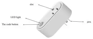
There is one button on the side of the device, it can be executed inclusion, exclusion, and reset from the Z-Wave™ network.
| Add’ | 1. Power up the device. 2. Set Z-Wave Controller into inclusion mode 3. Press and hold the button for 5s until Blue led lights are on, then release the button before the lead turns off. | Blue led will blink with Is interval until inclusion is successful. |
| Remove | 1. Power up the device. 2. Set Z-WaveTM Controller into exclusion mode 3. Press and hold the button for 5s until Blue led lights are on, then release the button before the lead turns off. | Blue led will blink with 0.5s interval until exclusion successful. |
| Factory Reset2 | 1. Power up the device. 2. Press and hold the button for Los until less light is on, then release the button before lead turns off. | |
| Product Test Mode | 1. Press and hold the button. 2. Power on the device, the device will enter factory product test mode with Blue light flash. | |
| Send NIP | Press and hold the button for 5s until Blue led lights is on, then release the button before lead turns off. |
Notice 1: When the device enters into inclusion mode, the device all functionality will be useless. The inclusion mode will be timeout after the 30s, the user can implement step 3 to terminate inclusion mode.
Notice 2: Factory Reset will clear the device all Z-Wave™ Network data (include home id, node id, etc…) saved in memory, and restore all configuration parameters to factory default. Please use this procedure only when the network primary controller is missing or otherwise inoperable.
Notice 3: NIF – Node Information Frame
Association
The device supports 2 association groups, and each group supports max 5 associated nodes.
Group 1, Lifeline – All nodes associated with group 1(lifeline group) will receive the messages that send by the device through the lifeline.
In group 2, all nodes associated in group 2 will be controlled by the device through the BASIC_SET command. When the device detects an over-current event, the device will trigger an OCP Alarm and send a notification report to the controller, the meantime device also sends a BASIC_SET = 0xFF to the nodes that are associated with group 2. And BASIC_SET = 0x00 will be sent after OCP Alarm Event is cleared.
The Command Class supported by each association group is shown in the table below:
| Group | Command Class | Command |
| I (Lifeline) | COMMAND_CLASS _SWITCH_BINARY COMMAND_CLASS_NOTIFICATION COMMAND_CLASS_METER COMMAND_CLASS_INDICATOR COMMAND_CLASS_DEVICE_RESET_LOCALLY | SWITCH BINARY REPORT NOTIFICATION REPORT METER REPORT INDICATOR REPORT DEVICE_RESET_LOCALLY_NOTIFICATION |
| 2 (Control) | COMMAND_CLASS_BASIC | BASIC SET |
Device Functionality and Z-Wave™ Message Report
The SmartPlug has four main functions: Switch On/Off, electrical parameters measurement over-current protection, and timing.
Switch On/Off
There are three ways of controlling the outlet switch:
- Press the button shortly
- Operated the device Via Z-Wave™ Controller or Others Devices that associated it by Command Class list as below table.
| SmartPlug State | Command Class | Command | Value |
| ON | COMMAND_CLASS_SWITCH_BINARY | SWITCH_BINARY_SET | OxFF |
| COMMAND_CLASS_BASIC | BASIC_SET | OxFF | |
| OFF | COMMAND_CLASS_SWITCH_BINARY | SWITCH_BINARY_SET | Ox00 |
| COMMAND_CLASS_BASIC | BASIC_SET | Ox00 |
Electrical Parameters Measuring
The device provides line voltage (V), loaded current (A), active power (W), and accumulated energy consumed (kWh) measurement; the significant digits of the measured result should be two digits after the decimal point;
These electrical parameters result will be reported to the Z-Wave™ controller regularly through the Meter Report of Meter Command Class, the interval of which can be configured by the user by means are shown in “Configuration: No.11″
The device also provides the function of reporting the measurement results to the Z-Wave™ the controller when the load current changes and the user can set the changed quantity of the load current freely by means shown in “Configuration: No.10”
The electric quantity detection result is reported to Command Class
| Command Class | Command | Scale | Precision |
| COMMAND-CLASS-METER | METER- REPORT | kWh | 0.0 kWh |
| Watt | 0.01W | ||
| Volt | 0.01V | ||
| Ampere | 0.01A |
The max cumulative energy is 21474836.47kWh, if it is over this value, it will be back to 0kWh automatically.
Reset Cumulative Energy
There have two ways to reset cumulative energy:
- Z-Wave gateway sends METER_RESET command to SmartPlug to reset the cumulative energy value.
- Execute the factory reset operation to reset the cumulative energy value.
The cumulative energy will not be reset if SmartPlug removes from Z-Wave Network by the exclusion operation.
Over-current Protection
The outlet can provide a maximum load current of 16A, and when the load current exceeds 16A, the load power supply will be automatically cut off. And it will inform the host of the overload of the outlet through NOTIFICATION_REPORT of the Notification Command Class, and meanwhile, the LED light of the outlet will flash with an interval of one second; Users can remove the overload alarm by pressing the button or sending SWITCH_BINARY_SET=0xFF, and for safety’s sake, before that, users should remove the load from the outletfirst.
Users can control the maximum output current of the outlet by setting the maximum output current, the setting method of which is shown in “Configuration: No. 8”.
Overload protection communication Command Class
| Command Class | COMMAND_CLASS_NOTIFICATION |
| Command | NOTIFICATION_REPORT |
| Type | NOTIFICATION_TYPE_POWER_MANAGEMENT (0x08) |
| Event | NOTIFICATION_EVENT_POWER_MANAGEMENT_OVERLOAD_DETECTED (0x08) |
Timer
The device also provides the function of timing, and users can turn off the outlet by opening this function and setting the time cycle, the setting method of which is shown in “Configuration: No.4 and Configuration No 11”.
Command Class Configuration
The device supports the controller to configure parameters of the device through Configuration Command Class, and the device has 11 parameters available for users to set according to their different needs:
- Relay On/Off state Saved Disable Sets this configuration to ‘1’, the device will save the current relay state, and after the device is powered down and restarted, it will automatically recover to the relay state before power-down. Set to ‘0’, the device won’t remember the previous state, default to being ON.
Parameter Number Size (Byte) Available Settings Default value 1 1 0, 1 1 - Button Switch Function Disable
Setting this configuration as ‘0’ will be disabling to turn on and off the relay by pressing a button.Parameter Number Size (Byte) Available Settings Default value 2 1 0, 1 1 - LED indication Disable
Setting this configuration as ‘0’ will disable the led light when turning on the device. This setting is invalid during device power-up.Parameter Number Size (Byte) Available Settings Default value 3 1 0, 1 1 - Countdown Timer Enable
Setting this configuration as ‘1’ will start the timing function of the plug, and the length of time is determined by the setting of “Configuration: No.7”.
This function can only provide the time to turn off the device function when the device is open.Parameter Number Size (Byte) Available Settings Default value 4 1 0, 1 0 - Meter Enable
This configuration sets the meter Monitoring function enabled or disabled.
‘0’ – Disable meter measuring Function.
‘1’ – Enable meter measuring Function.
Note: If this configuration is set to ‘0’, all the functions of “Configuration No. 6, 8, 9, 10, 11” are invalid. And No Current, Voltage, Active Power and Accumulated Power monitored and reported anymore.Parameter Number Size (Byte) Available Settings Default value 5 1 0, 1 1 - Meter Report Enable
This configuration sets the meter report function enabled or disabled.
‘0’ – Disable meter report function.
‘1’ – Enable meter report function with time interval defined by “Configuration No. 11”.
When the device is detected an OCP event or the relay turned on or turned off, the device still will report all meter values once this value is set to ‘0’.Parameter Number Size (Byte) Available Settings Default value 6 1 0, 1 1 - Countdown Time Setting
This configuration sets the time length for turning off the device. This configuration is only valid when “Configuration No.4” is set to ‘1’. Unit: minute.Parameter Number Size (Byte) Available Settings Default value (min) 5 2 0 ~ 30000 120 - Maximum output current setting
This configuration sets the maximum output current that the device can provide. When the current consumed by the load is greater than the setting value, the device will automatically cut off the power of the load and send out alarm information, and the led will light on 1.5s with 2s interval. Unit: 0.01A (Ampere).
This value must be great than the alarm value defined by Configuration No. 9.Parameter Number Size (Byte) Available Settings Default value 8 2 0 ~ 1600 1600 - Output Current Alarm
This configuration sets the alarm value of the load current (volatility). When the load current is large than this value, the led will light on 0.5s with 2s interval. Unit: 0.01A (Ampere). This value must be less than the max. output value defined by Configuration No. 8.Parameter Number Size (Byte) Available Settings Default value 9 2 0 ~ 1550 1500 - Current Change Ratio
This configuration sets the changed value of the load current (volatility). When the differential between two measurements of current consumed by the load exceeds the value set by this configuration, the device will report the last measured results automatically to the controller.
The changed value = [Value] × 0.01A.Parameter Number Size (Byte) Available Settings Default value 10 2 0 ~ 1000 50 - Interval of meter reporting setting
This configuration sets the interval of reporting electric quantity detection results. This parameter is only valid when Parameter 6 is set as ‘1’. Unit: Second.Parameter Number Size (Byte) Available Settings Default value 11 2 0 ~ 30000 300
- To Simulate Over Current Protection Function, First User Must Turn on SmartPlug And Then Write 1 Byte Data 0xFF(255) to Parameter Number 99. SmartPlug will Be Turned Off And Report Alarm Messages to Hubs. Meantime Blue Led Will Blink with 1s Interval. This must set “Configuration No. 5” to ‘1’.
Command Class Basic
The Basic Command Class is mapped to Switch Binary Command Class as Follow:
- Basic Set = 255 maps to Binary Switch Set = 255
- Basic Set = 0 maps to Binary Switch Set = 0
- Basic Set = 1 ~ 99 maps to Binary Switch Set = 255
- Basic Get/Report maps to Binary Switch Get/Report
SmartStart
SmartStart enabled products can be added into a Z-Wave network by scanning the Z-Wave QR Code present on the product with a controller providing SmartStart inclusion. No further action is required and the SmartStart product will be added automatically within 10 minutes of being switched on in the network vicinity.
This device supports the SmartStart function. QR code is printed on the label that is pasted on the surface of the product and the outside of the packing box. And the full DSK code is printed can be found on the packing box.
The device will enter SmartStart if the device is not included in the network after power-up. And then
2nd SmartStart time delay approximately 16s
3rd SmartStart time delay approximately 32s
4th SmartStart time delay approximately 64s
5th SmartStart time delay approximately 128s
6th SmartStart time delay approximately 256s
7th SmartStart time delay approximately 512s
Afterward, the Smartstart mode will be auto running at 512-second intervals until the device is included successfully.
Security Network
The device supports the security function with S2 + SmartStart encrypted communication. The device will auto switch to the security mode when the device is included with a security controller. In the security mode, the following commands must use security or security_2 command class wrapped to communicate, otherwise, the device will not respond to any commands.
Security Keys
This device supports the security levels are listed in below table:
| Security Levels | Support (Yes/No) |
| SECURITY_KEY_SO | Yes |
| SECURITY_KEY_S2_UNAUTHENTICATED | Yes |
| SECURITY_KEY_S2_AUTHENTICATED | Yes |
| SECURITY_KEY_S2_ACCESS | No |
All Supports Command Class in Each NIF Lists
| Command Class | Version | Not Included | Non-secure Included | SO Included | S2 Included | ||
| Non-Secure | Secure | Non-Secure | Secure | ||||
| COMMAND_CLASS_ZWAVEPLUS_INFO | 2 | • | • | • | • | ||
| COMMAND_CLASS_SECURITY | I | • | • | • | |||
| COMMAND_CLASS_SECURITY_2 | I | • | • | • | • | ||
| COMMAND_CLASS_TRANSPORT SERVICE | • | • | • | • | |||
| COMMAND_CLASS_VERSION | 3 | • | • | • | • | ||
| COMMAND_CLASS_POWERLEVEL | I | • | • | • | • | ||
| COMMAND_CLASS_ASSOCIATION | 2 | • | • | • | • | ||
| COMMAND_CLASS_MULTI CHANNEL_ASSOCIATION | 3 | • | • | • | |||
| COMMAND_CLASS_ASSOCIATION_GRP_INFO | I | • | • | • | • | ||
| COMMAND_CLASS_MANUFACTURER_SPECIFIC | 2 | • | • | • | • | ||
| COMMAND_CLASS_DEVICE_RESET_LOCALLY | I | • | • | • | • | ||
| COMMAND_CLASS_SWITCH_BINARY | 2 | • | • | • | • | ||
| COMMAND_CLASS_NOTIFICATION | 8 | • | • | • | • | ||
| COMMAND_CLASS_METER | 5 | • | • | • | |||
| COMMAND_CLASS_INDICATOR | 3 | • | • | • | • | ||
| COMMAND_CLASS_CONFIGURATION | 4 | • | • | • | • | ||
| COMMAND_CLASS_SUPERVISION | 1 | ● | ● | ● | ● | ||
| COMMAND_CLASS_FIRMWARE_UPDATE_MD | 5 | ● | ● | ● | ● | ||
Notice 1: When the device is included with S0 level, COMMAND_CLASS_MANUFACTURER_SPECIFIC is supported non-securely. And when the device is included with S2 level, COMMAND_CLASS_MANUFACTURER_SPECIFIC is supported securely only.
Notice 2: “●” – Indicates the corresponding command class is supported in NIF, Blank means the command class is not supported.
Led Color Indicator
| Led Color | Action | Description |
| Blue | Blink with is Interval When Power On | Not Add in Z-Wave Network |
| Light On is When Power On | Add in Z-Wave in Network Already | |
| Blink With 2s Interval | Over Current Detected, SmartPlug Turn Off. | |
| Light On 2s | Press And Hold Button 10s, Off at 12th Second | |
| Press And Hold Button 5s, Off at 7th Second | ||
| Light On Always | SmartPlug Turn On | |
| Blink with 500ms Interval | Remove from Z-Wave Network/Send NIF | |
| Blink with is Interval | Add to Z-Wave Network | |
| Blink with 300ms Interval ‘ | OTA is Running |
Note 1: The LED State is Not Changed when Led Is Busy (On or Blink, Such as Relay on, Over Current Detected).
If Led Is Idle, the OTA Led State Will Be Running, And then the LED state is not changed until OTA is finished.
Specifications
| Power Supply | 110 — 230V AC, f 10%, 50/60Hz |
| Power Consumption | Up to 0.8W |
| Operational Temperature | 0 – 70°C |
| Communication frequency | 868.40MHz, 869.85MHz (EU) 908.40MHz, 916.00MHz(US) |
| Range | Up to 45m indoors (depending on the building structure), and 80m for outdoor open fields. Up to 80m outdoors. |
FCC STATEMENT :
This device complies with Part 15 of the FCC Rules. Operation is subject to the following two conditions:
This device may not cause harmful interference, and
This device must accept any interference received, including interference that may cause undesired operation.
Warning: Changes or modifications not expressly approved by the party responsible for compliance could void the user’s authority to operate the equipment.
NOTE: This equipment has been tested and found to comply with the limits for a Class B digital device, pursuant to Part 15 of the FCC Rules. These limits are designed to provide reasonable protection against harmful interference in a residential installation. This equipment generates uses and can radiate radio frequency energy and, if not installed and used in accordance with the instructions, may cause harmful interference to radio communications. However, there is no guarantee that interference will not occur in a particular installation. If this equipment does cause harmful interference to radio or television reception, which can be determined by turning the equipment off and on, the user is encouraged to try to correct the interference by one or more of the following measures:
Reorient or relocate the receiving antenna.
Increase the separation between the equipment and receiver.
Connect the equipment into an outlet on a circuit different from that to which the receiver is connected.
Consult the dealer or an experienced radio/TV technician for help.
FCC Radiation Exposure Statement:
This equipment complies with FCC radiation exposure limits set forth for an uncontrolled environment. This equipment should be installed and operated with a minimum distance of 20cm between the radiator & your body.


