BFT KLEBR93531705 Dual Swing Gate Operator Kit
 INSTALLATION MANUAL
 INSTALLATION MANUAL
GENERAL INFORMATION
- Electromechanical operator designed to automate residential-type gates.
- The gearmotor keeps the gate locked on closing and on opening, without needing an electric lock for leaves up to 3 m long. For leaves ranging between 3m and 5m long, the electric lock becomes indispensable.
- The operator is provided with an electronic torque limiter. It must be controlled by an electronic control panel provided with torque setting.
- The end-of-stroke operation is controlled by two magnetic limit devices.
- The operator is provided with an obstacle detection system complying with EN12453 and EN 12445 standards.
- The following optional accessories are available on request:
- Buffer battery kit mod. BT BAT
- Allows operation of the automation even when there is no mains power supply for a short period of time
TECHNICAL SPECIFICATIONS
| 3) TECHNICAL SPECIFICATIONS | |
| Power supply | 24V |
| Max. Absorbed power | 40 W |
| Absorbed current | 1,5 A |
| Push and pull force | 2000 N (~200 kg) |
| Stem speed | 15 mm/s approx. |
| Impact reaction | Torque limiter aboard control board |
| Limit devices | Magnetic, incorporated and adjustable |
| Manual manoeuvre | Personalized release key |
| Environmental conditions | – 20°C a +55°C |
| Type of use | semi-intensive |
| Maximum leaf length without electric lock | 2 m KUSTOS ULTRA BT A25 |
| 3 m KUSTOS ULTRA BT A40 | |
| Maximum leaf length with elec- tric lock | 2,5 m KUSTOS ULTRA BT A25 |
| 4 m KUSTOS ULTRA BT A40 | |
| Max. leaf weight | 4000 N (~400 kg) KUSTOS ULTRA BT A25 |
| 5000 N (~500 kg) KUSTOS ULTRA BT A40 | |
| Protection level | IP 44 |
| Controller weight | 50N (~5kg) KUSTOS ULTRA BT A25 |
| 77N (~7,7kg) KUSTOS ULTRA BT A40 | |
| Dimensions | See Fig. L |
| Lubrication | permanent grease |
| Sound pressure | LpA<70dbA |
MAXIMUM LENGTH/DOOR WEIGHT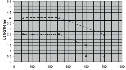
TUBE ARRANGEMENT
Install the electrical system referring to the standards in force for electrical systems CEI 64-8, IEC 364, harmonization document HD 384 and other national standards.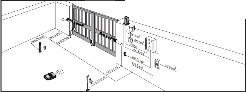
INSTALLATION DIAGRAM
- P rear bracket fastening to pillar
- F front fork fastening leaf
- a-b distances for determining bracket “P” fastening point
- C value of fastening centre-to-centre distance
- D gate length
- X distance from gate axis to corner of pillar
- S half door thickness
- Z value always greater than 45 mm (b – X)
- kg max. weight of leaf
- α° leaf opening angle

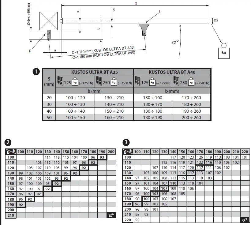
PILLAR FASTENINGS INSTALLATION DISTANCES
How to read the installation distance tables
Select “a” and “b” according to the angle in degrees α° that the gate has to open. The optimum “a” and “b” values for 92° opening at constant speed are highlighted. If there is too large a difference between “a” and “b”, the leaf will not travel smoothly and the pushing or pulling force will fluctuate during its stroke. To respect the opening speed and ensure the controller operates correctly, it is best to keep the difference between “a” and “b” as low as possible. The table has been worked out for A40 mm (KUSTOS BT A40), 20 mm (KUSTOS ULTRA BT A25) thick medium-size gate. Always check that there is no possible collision between the gate and the operator.
FASTENING OF FITTINGS TO PILLAR 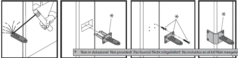
POWER CABLE
The board power supply cable must be of the H05RN-F type or equivalent. The equivalent cable must guarantee: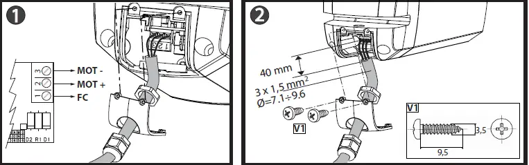
- permanent outside use
- maximum temperature on the cable surface of +50° C
- minimum temperature of -25° C
If the motor vibrates but does not rotate, the problem may be:
- Incorrect wiring (see wiring diagram)
- If the leaf moves in the wrong direction, swap over the motor’s start connections in the control unit.
- The first command following a mains power outage should be open LEAF STOPS.
ATTACHING MOTOR TO FASTENING ON PILLAR 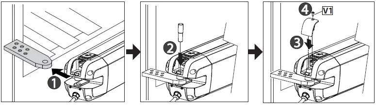
MAXIMUM TILT 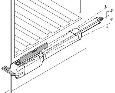
CORRECT INSTALLATION
Correct installation entails maintaining a rod stroke margin of approx. 5-10 mm to avoid possible trouble with operation.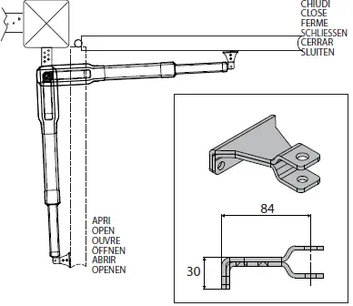
FASTENING OF FITTINGS TO LEAF
Line up the front and rear brackets 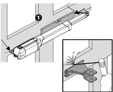
OPERATOR ATTACHMENT ON DOOR 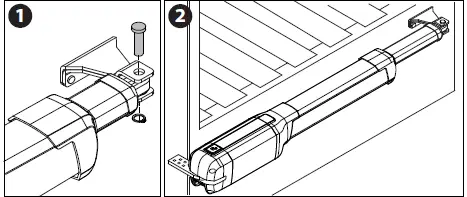
LIMIT DEVICE ADJUSTMENT
ATTENTION! To avoid braking the limit switch cable, tighten screw A keeping the wire B well tightened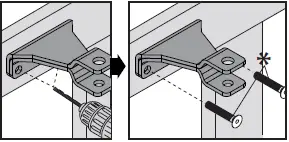 DIMENSIONS
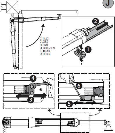
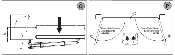
TIPS FOR SPECIAL INSTALLATIONS
- With the leaf fully open, create a recess to accommodate the operator. gives the minimum dimensions of the recess for the various KUSTOS ULTRA BT A25 –
- KUSTOS ULTRA BT A40 models. If distance “b” is greater than the values given in the installation tables:
- create a recess in the pillar
- move the leaf so that it is flush with the pillar
LEAF STOPS AT GROUND LEVEL
For the actuator to work properly, it is advisable to use stops “Rif. 1” to stop the leaves both when they are open and closed, as illustrated in The leaf stops must prevent the actuator rod from reaching the end of its travel.
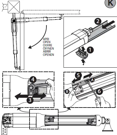
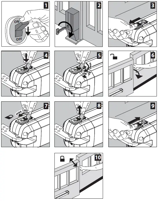
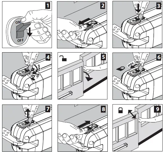
MANUAL OPENING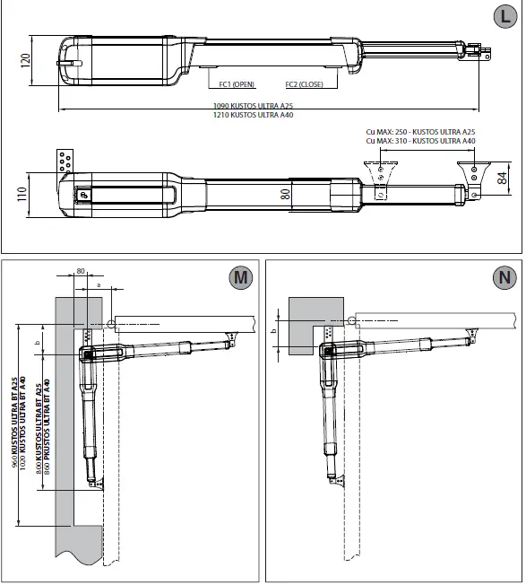
ELECTRIC LOCK
WARNING: In the case of leaves longer than 3m, it is indispensable to install a solenoid latch. For electric lock connection, the optional board is required (refer to the appropriate instruction).
USER GUIDE: EMERGENCY OPERATION