Worthcloud
Technology W-BW2K Wi-Fi Module
User Manual
Version: 20210902
Product description
1.1description
It is worth watching the W-BW2K embedded Wi-Fi +BT module provides a solution for connecting the user’s physical device to the Wi-Fi wireless network or BLE Bluetooth direct connection and provides a UART serial port and other data processing solutions, through this module, traditional low-end serial devices or MCU-controlled devices can easily access Wi-Fi or BLE wireless networks, so as to achieve IoT network control and management.
It is worth seeing that the W-BW2K module adopts the industry’s low-power embedded structure, and has been professionally optimized for applications in low-flow and low-frequency data transmission fields such as smart furniture, smart grids, and handheld devices, personal medical care, and industrial control.
It is worth seeing that the W-BW2K module is a compact module that integrates all Wi-Fi & BLE functions, and is easy to integrate on the hardware PCB single-board circuit of the customer’s product. It is equipped with a built-in PCB antenna and supports IPEX external antennas.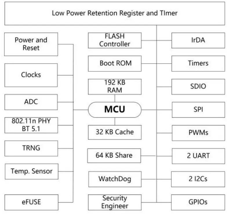 Figure 1. System Block Diagram
1.2 Features
- Support Wi-Fi 802.11b/g/n and BLE 5.1 wireless standards
- Using 32-bit MCU, the main frequency is up to 120MHz, 256KB RAM, 2MB
- Flash Support Wi-Fi/BLE to UART data communication Support Wi-Fi STA/AP, and Direct working mode
- Support AP and STA dual roles in parallel
- 50 MHz clock frequency SDIO
- Six PWM outputs supporting high-speed clock or low-power clock
- Support wireless and remote firmware upgrade, provide a wireless batch configuration tool
- SDK development kit is available to support secondary development
- Supports different types of antenna options
- Built-in PCB antennaSupport IPEX external antenna
- 3.3V single power supply
- Dimensions:
- 16mm x 24mm x 3mm, SMD16 package
1.3 Main application areas
- Intelligent lighting
- Smart socket
- Intelligent building
- Industrial control
- Remote device monitoring
- IoT applications
1.4Module basic parameters
Table1. It is worth seeing the technical parameters of W-BW2K module
| Classification | parameter | value |
| Wi-Fi | wireless standard | 802.11 b/g/n |
| Frequency Range | 2.412GHz-2.472GHz | |
| transmit power | 802.11b: +18dBm ± 1dBm (@11Mbps) | |
| 802.11g: +15dBm ± 1dBm (@54Mbps) | ||
| 802.11n: +14dBm ± 1dBm (@HT20, MCS7) 802.11n: +14dBm ± 1dBm (@HT40, MCS7) | ||
| Receive sensitivity | 802.11b: -98dBm (@1Mbps) | |
| 802.11b: -88dBm (@11Mbps) | ||
| 802.11g: -90dBm (@6Mbps) | ||
| 802.11g: -75dBm (@54Mbps) | ||
| 802.11n: -72dBm (@MCS7) | ||
| BLE | wireless standard | BLE5.1 |
| Frequency Range | 2.402GHz-2.480GHz | |
| transmit power | Max 10dBm | |
| Receive sensitivity | -96 dBm | |
| Hardware parameters | antenna | PCB antenna |
| Data interface | CART | |
| GPIO, SPI, PWM, ADC, I2C, IR | ||
| GPIO | source current:3mA(VCC-0.3V) sink current:3mA(GND+0.3V) | |
| Operating Voltage | 2.7~3.6V | |
| Working current | TX=17 dBm, 802.11b 11 Mbps type:210 mA TX=15 dBm, 802.11g 54 Mbps type:170 mA RX=-10 dBm,802.11b 11 Mbps type:50 mA RX=-10 dBm,802.11g 54 Mbps type:60 mA | |
| Operating temperature | -40℃- 105℃ |
| storage temperature | -40℃- 125℃ | |
| humidity | <85% | |
| Moisture Level (MSL) | Level 3 | |
| size | 16mm x 24mm x 3mm | |
| Software parameters | Wireless network type | STA/AP |
| Security Mechanism | WEP/WPA-PSK/WPA2-PSK/WPA3-SAE | |
| encryption type | WEP64/WEP128/TKIP/AES | |
| upgrade firmware | local wireless Remote upgrade | |
| Custom Development | Provide SDK for secondary development of customers | |
| Network protocol | IPv4, TCP/UDP/HTTP/TLS 1.2 | |
| User configuration | AT+ command set, Web page |
HARDWARE INTRODUCTION
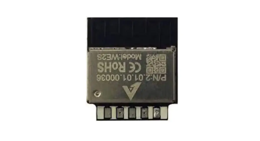
The appearance of the combo series Wi-Fi module is as follows.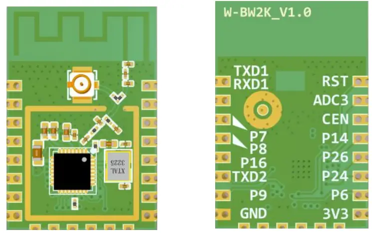 Figure 2. The appearance of W-BW2K
PIN DEFINITION

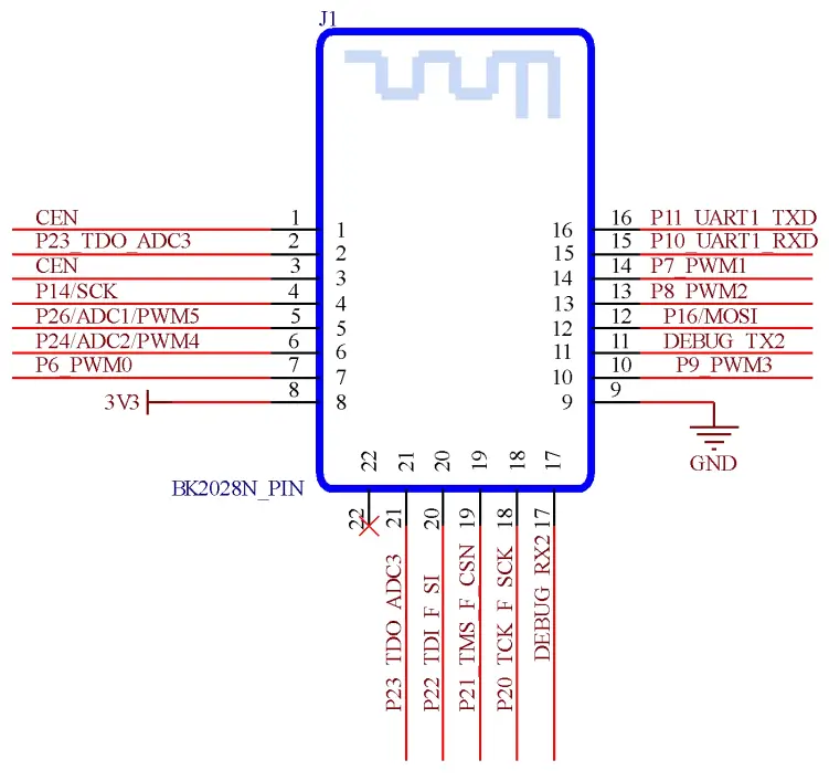
Figure 3. W-BW2K Pin Definition
Table1. W-BW2K pin function definition
| pin | describe | signal type | illustrate |
| 1 | RST | I | Low-level reset, high-level active (internally pulled high) corresponds to IC-CEN |
| 2 | P23/ADC3/TDO/ F_SO | IO | Set high when general IO port or ADC4 or RF receiving |
| 3 | CEN | I | Enable pin, internal pull-up processing, compatible with other module design docking |
| 4 | P14/SD_CLK/SCK /ANT0 | IO | General IO port or SD CLK or SPI SCK or BLE antenna control ANT0 |
| 5 | P26/ADC1/IRDA/ PWM5 | IO | General IO port or ADC1 or infrared receiver or PWM5 |
| 6 | P24/ADC2/LPO_ CLK/PWM4 | IO | General-purpose IO port or ADC2 or low power clock 32.768K output or PWM4 |
| 7 | P6/CLK13M/PW M0 | IO | General-purpose IO port or crystal clock divided by 1, 2, 4, 8 output or PWM0 |
| 8 | 3V3 | I | power supply |
| 9 | GND | I | GND |
| 10 | P9/BT_PRIORITY/PWM3 | IO | Common IO port or BT_PRIORITY control or PWM3 for the coexistence of WIFI and BT |
| 11 | P0/UART2_TXD/I 2C2_SCL | IO | General-purpose IO port or serial port UART2’s TXD or I2C2’s SCL |
| 12 | P16/SD_CMD/M OSI/ANT2 | IO | Universal IO port or SD’s CMD or SPI’s MOSI or BLE antenna to control ANT2 |
| 13 | P8/BT_ACTIVE/P WM2 | IO | Common IO port or BT_ACTIVE control or PWM2 for the coexistence of WIFI and BT |
| 14 | P7/WIFI_ACTIVE/ PWM1 | IO | Common IO port or WIFI_ACTIVE control or PWM1 where WIFI and BT coexist |
| 15 | P10/DL_RX/UAR T1_RXD | IO | General IO port or RXD downloaded by UART for FLASH or RXD of serial port UART1 |
| 16 | P11/DL_TX/UART 1_TXD | IO | General IO port or TXD downloaded by UART for FLASH or TXD of serial port UART1 |
| 17 | P1/UART2_RXD/I 2C2_SDA | IO | RXD of general IO port or serial port UART2 or SDA of I2C2 |
| 18 | P20/I2C1_SCL/TC K/F_SCK | IO | General-purpose IO port or SCL of I2C1 or TCK of JTAG or Flash using SPI to download the clock |
| 19 | P21/ADC6/I2C1_ SDA/TMS/ F_CSN | IO | General-purpose IO port or SDA of ADC6 or I2C1 or TMS of JTAG or Flash when downloading with SPI Chip select |
| 20 | P22/ADC5/CLK_2 6M/TDI/ TXEN/F_SI | IO | General IO port or ADC5 or crystal frequency output or TDI of JTAG or set high when transmitting or data input when Flash is downloaded by SPI |
| 21 | P23/ADC3/TDO/ F_SO | IO | General-purpose IO port or ADC3 or JTAG TDO or Flash data output when downloaded with SPI |
| 22 | NC | – | empty pin |
ELECTRICAL CHARACTERISTICS
Table2. Electrical Characteristics
| parameter | condition | min | type | max | unit |
| Maximum Soldering Temperature | IPC/JEDEC J-STD-020 | – | – | 260 | °C |
| Electrostatic discharge (Human Body Model HBM) | TAMB=25°C | – | – | 2.5 | KV |
| Electrostatic discharge (MM) | TAMB=25°C | – | – | 0.25 | KV |
MECHANICAL DIMENSIONS
The physical dimensions of W-BW2K (unit: mm) are as follows: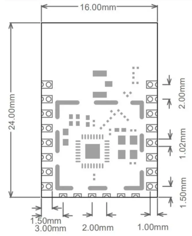 Figure 4. W-BW2K Mechanical Dimensions
TYPICAL APPLICATION
6.1 Antenna layout requirements
- For the installation position of the module on the motherboard, the following two methods are recommended:
Solution 1: Put the module on the edge of the motherboard, and the antenna area extends out of the edge of the motherboard.
Option 2: Put the module on the edge of the motherboard, and hollow out an area on the edge of the motherboard at the antenna position. In order to meet the performance of the onboard antenna, it is forbidden to prevent metal devices around the antenna and keep away from high-frequency devices.
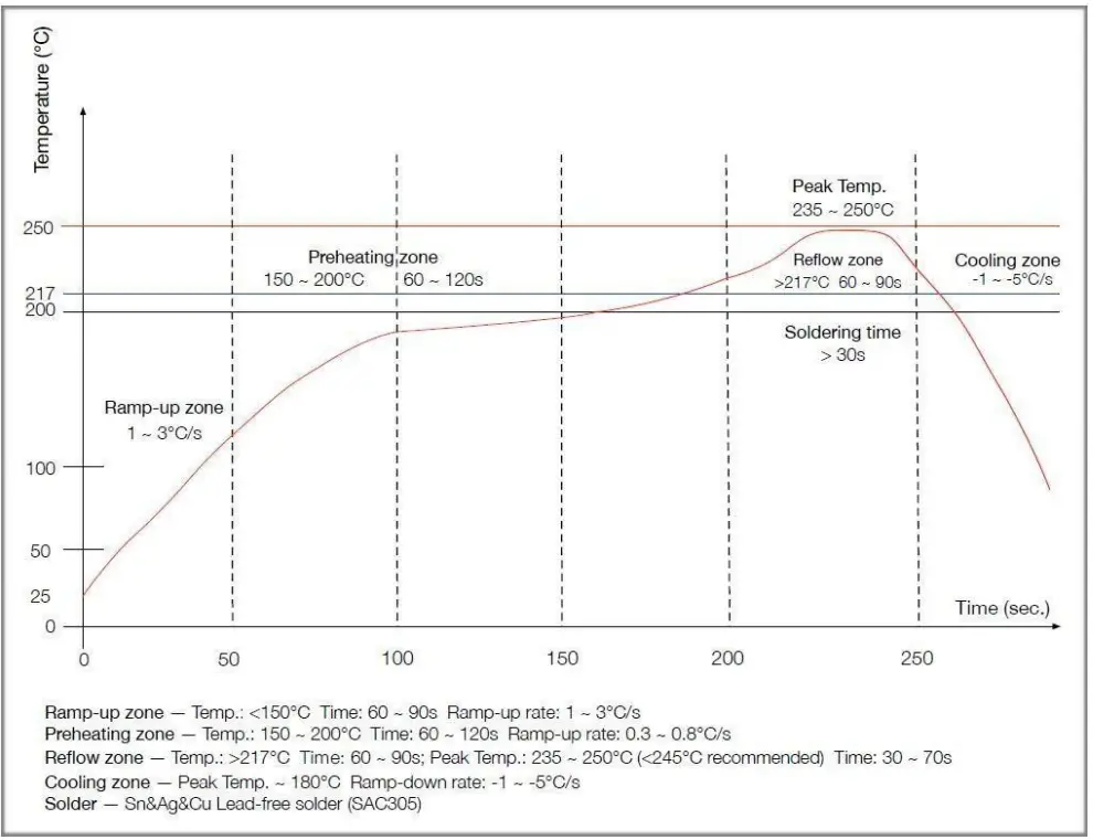
REFLOW SOLDERING CONDITIONS
- Heating method: conventional convection or IR convection;
- Allowable reflow times: 2 times, based on the following ramped heating conditions;
- Maximum temperature: 250°C.

FCC warning statements:
This equipment has been tested and found to comply with the limits for a Class B digital device, pursuant to part 15 of the FCC Rules. These limits are designed to provide reasonable protection against harmful interference in a residential installation. This equipment generates, uses, and can radiate radio frequency energy and, if not installed and used in accordance with the instructions, may cause harmful interference to radio communications. However, there is no guarantee that interference will not occur in a particular installation. If this equipment does cause harmful interference to radio or television reception, which can be determined by turning the equipment off and on, the user is encouraged to try to correct the interference by one or more of the following measures:
- Reorient or relocate the receiving antenna.
- Increase the separation between the equipment and receiver.
- Connect the equipment into an outlet on a circuit different from that to which the receiver is connected.
- Consult the dealer or an experienced radio/TV technician for help.
Caution: Any changes or modifications to this device not explicitly approved by the manufacturer could void your authority to operate this equipment.
This device complies with part 15 of the FCC Rules. Operation is subject to the following two conditions: (1) This device may not cause harmful interference, and (2) this device must accept any interference received, including interference that may cause undesired operation.
The device has been evaluated to meet general RF exposure requirements This equipment complies with FCC radiation exposure limits set forth for an uncontrolled environment. This equipment should be installed and operated with a minimum distance cm between the radiator & your body.


