vetus FTLD B Interconnection Kit For Rigid Fuel Tanks
Introduction
This manual is applicable to the installation of the interconnection kit for rigid fuel tanks. The tank may be made from plastic, GRP or metal and should have a minimum wall thickness of 1.5 mm.
Note
Refer to the tank’s installation manual. Ensure proper venting so that the tank is pressure-free at all times.
Installation
Cutting the hole for the connector lid and the holes for the coupler
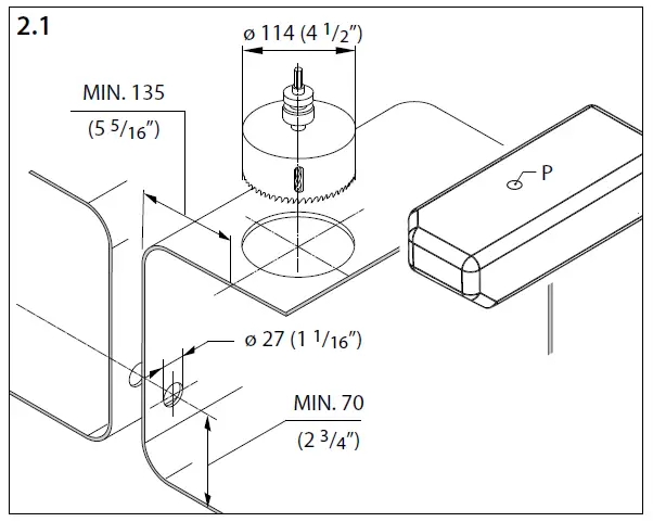
- Position the connector lid on the top face of the tank. If a VETUS tank is used, then it should be fitted with plug P on the top and the connector lid should preferably be located so that plug P is removed when the hole is cut.
- Cut the hole in the tank and remove all burrs.
Note!
Drill an exactly round hole using a hole saw (ø 114mm, 4 1/2” diam.). This is essential in order to achieve proper sealing. A ø 114 mm hole saw is available from VETUS under art. code VSAW114.
- Drill a hole at the minimum height shown in the drawing in both tanks (27 mm, 1 1/16” diam.) for the coupler.
- Clean the inside of the tanks before fitting the connector lid.
Rubber seal to be applied
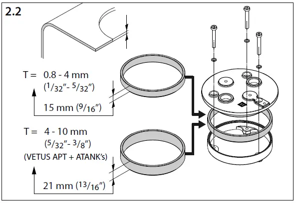
- Determine the thickness of the wall of the tank and use the indicated rubber seal.
Installation coupler
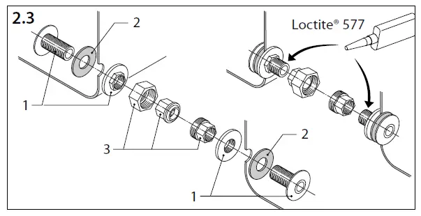
- Install a skin fitting (1) with gasket (2) in both tanks.
- Fit the coupler halves (3) to the skin fittings and apply a fuel resistant sealant, e.g. Loctite® 577 to the threads.
- Position the tanks next to each other and connect them with the coupling nut.
Installation of connector lid
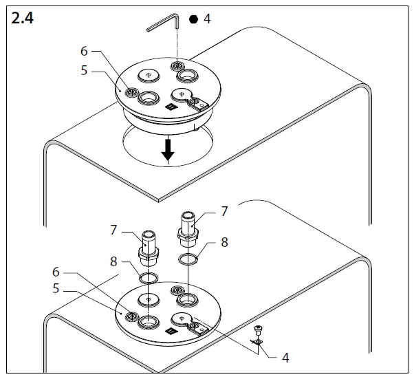
Connector lid (5)
- Position the connector lid (5) into the hole of the tank.
- Tighten each of the 3 screws (6) one (-1-) revolution (clockwise) and check if the lid can be rotated easily by hand.
- Repeat this until the lid can’t be rotated anymore. Then tighten each of the screws another three (-3-) revolutions.
Tank vent (7)
- Fit the hose pillar with the sealing washer (8).
Earth connection (4)
- Fit the terminal tag.
Ventilation line
- Connect the tank vent line as indicated in the drawing on page 6.
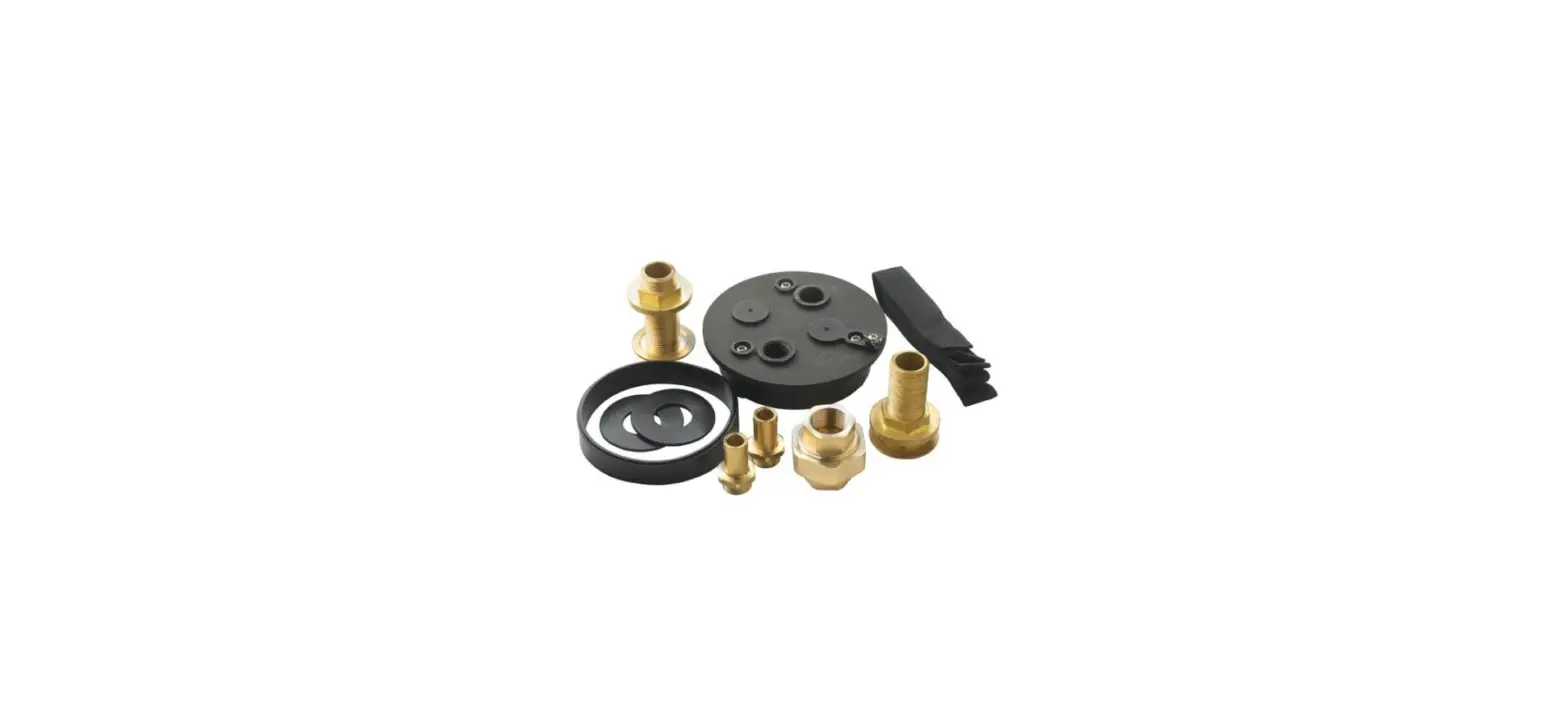
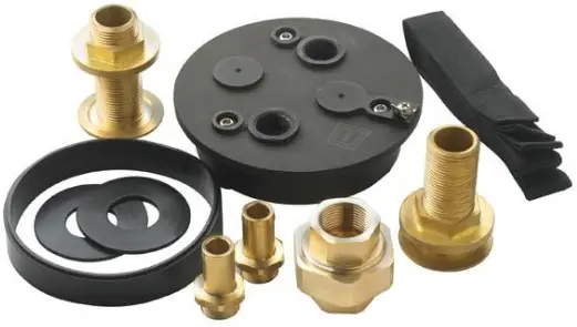
PARTS
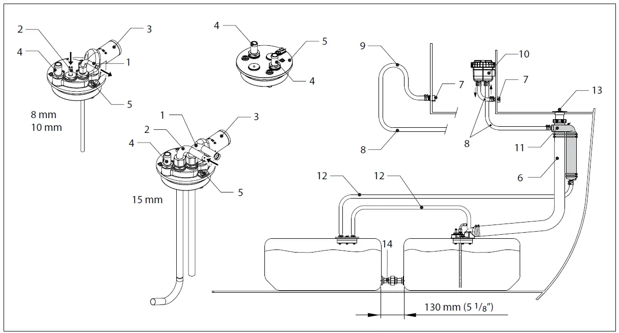
- Fuel supply
- Fuel return
- Filling connection, ø 38 / ø 51 mm
- Tank vent (hose pillar)
- Earth connection (terminal tag)
- Filler hose, ø 38 / ø 51 mm
- Breather nipple
- Vent hose, ø 16 mm
- Goose neck
- Odour filter
- Fuel overflow
- Breather / overflow pipe, ø 16 mm
- Filler cap
- Coupler
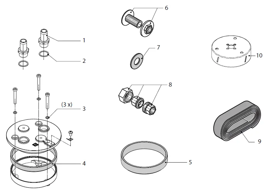
Service parts
pos. qty part description
- 1 2 FTL003 Hose pillar M20 – 16 mm
- 2 2 R201K Washer, copper
- 3 1 FTL011 Washer, fibre
- 4 1 FTL001 Rubber seal, for wall thickness 1.5 up to 4 mm
- 5 1 FTL021 Rubber seal, for wall thickness 4 up to 10 mm
- 6 2 DOORB3/4 Skin fitting 3/4″
- 7 2 WTK14 Gasket
- 8 1 WTK15 Coupler
- 9 2 WTK01 Mounting strap 30 mm – 175 cm
- 10 1 VSAW114 Hole saw ø 114 mm
FOKKERSTRAAT 571 – 3125 BD SCHIEDAM – HOLLAND TEL.: +31(0)88 4884700 – [email protected] – www.vetus.com
Printed in the Netherlands 040107.03 2022-03


