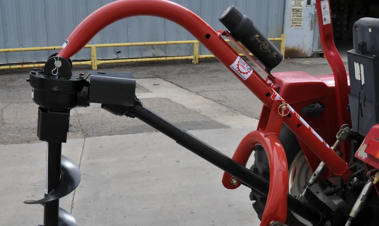
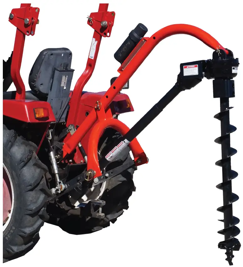
Agknx 400 3-Point Post Hole Digger
IMPORTANT SAFETY INFORMATION
- WARNING:
Read and thoroughly understand all instructions and safety information before assembling or operating this post hole digger. Failure to do so may cause serious injury or death. Do not allow anyone to operate this post hole digger who has not read this manual. As with all power equipment, a post hole digger can be dangerous if assembled or used improperly. Do not operate if you have doubts or questions concerning safe operation. Call our customer service department at 303-278-0664,or email at [email protected] if you have any questions or concerns about the safe operation of this equipment. - INTENDED USE
Do not use the post hole digger for any purpose other than digging post holes in the soil when connected to a 3-point linkage system and power take off of a tractor. Any other use is unauthorized and may result in serious injury or death. - PERSONAL PROTECTIVE EQUIPMENT:
When operating this post hole digger it is essential that you wear safety gear including safety glasses, steel toe shoes and tight fitting gloves (no loose cuffs or draw strings). - Do Not wear loose clothing or jewelry that can be caught by moving parts of the post hole digger including the auger and driveline. Keep clothing and hair from all moving parts when operating.
GENERAL SAFETY
Failure to follow warnings, cautions, assembly and operation instructions in the Operation Manual may result in serious injury or death.
Read the Operation Manual before operation.
- Do not permit children to operate this equipment at any time. Do not permit others that have not read and understood the complete Operation Manual to operate this equipment.
- Keep all people and pets a minimum of 10 feet away from the work area when operating this post hole digger. Only the operator is to be near the post hole digger during use.
- Do not operate the post hole digger when under the influence of alcohol, drugs or medication.
- Do not allow a person who is tired or otherwise impaired or not completely alert to operate the post hole digger.
- Always check with authorities for underground utilities before digging holes. Serious injury or death could result from contact with gas or electric lines.
- Read the Tractor’s operation manual concerning the proper attachment and use of 3-point equipment and safety.
- Always make sure that all safety shields are in place and securely fastened. Do not operate if any shields are missing.
- Make sure that the auger point and cutting edges are intact and in good working condition prior to use.
- ALWAYS OPERATE THIS POST HOLE DIGGER FROM THE TRACTOR SEAT. ONLY ONE PERSON SHOULD OPERATE THE DIGGER.
- DO NOT ATTATCH THE POST HOLE DIGGER TO THE TRACTOR WITH THE ENGINE RUNNING.
- DO NOT OPERATE THE POST HOLE DIGGER WITH ANYONE IN CONTACT WITH ANY PART OF THE IMPLEMENT, PTO DRIVELINE OR AUGER.
- SERIOUS INJURY CAN RESULT FROM ENTANGLEMENT WITH MOVING PARTS.
DANGER:
- Make sure that the tractor brake is set before deploying the post hole digger.
- Do not manually deploy the auger.
- Do not manually position or force the auger into the ground.
- Turn off tractor engine before leaving the seat of the tractor.
- Do not move the tractor with the power take off in the ON position.
- Do not exceed the 540 RPM PTO operating speed.
- NEVER OPERATE THE POST HOLE DIGGER WITH THE AUGER MORE THAN 6 INCHES ABOVE THE GROUND LEVEL. Operating the post hole digger in an elevated position may cause the PTO driveline u-joints to bind resulting in equipment damage and operator injury.
- ALWAYS turn off the post hole digger if a rock or other obstacle is encountered during operationg to prevent damage to the gearbox and possible operator injury. Shear bolts could become welded to the input shaft of the drive shaft if left running after being sheared.
- If the auger is stuck do not pull the auger out using the tractor. Damage to the digger boom and gearbox can occur. Turn off the tractor, disconnect the auger from the gearbox and manual remove the auger from the hole.
- ONLY PERFORM MAINTENANCE such as lubrication, adjustments and repairs with the tractor engine turned off, the PTO disengaged and the auger point resting at ground level.
- ALWAYS replace shear bolts with the correct shear bolt size and grade (SAE Grade 5). Never use a shear bolt that is longer or larger than what is specified in the operation manual for that post hole digger model.
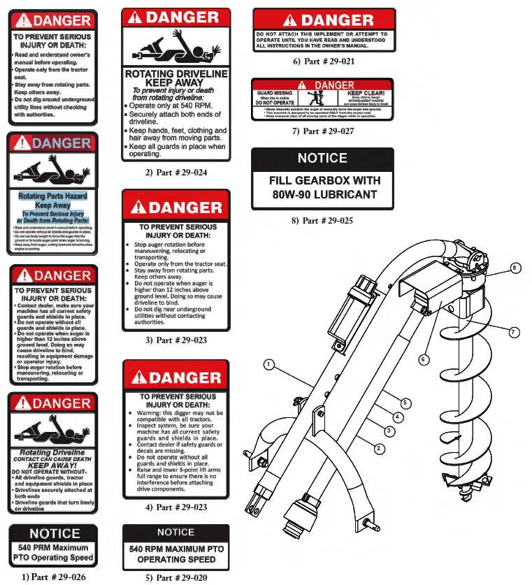
SAFETY DECALS
Make sure all safety warning decals are attached and in readable condition. Replace missing or defaced decals. Contact AGKNX at 303-278-0664 for replacement decals.
ASSEMBLY INSTRUCTIONS
- STEP 1:
The gear box is shipped without lubricant. Fill the top hole with EP90 lubricant or equivalent. The gear box holds 25 fluid oz. (0.7 liters). Fill to the bottom of the plug on the side. Do not overfill as this can cause damage to the seals. Check the oil level every 50 hours of operation. - STEP 2:
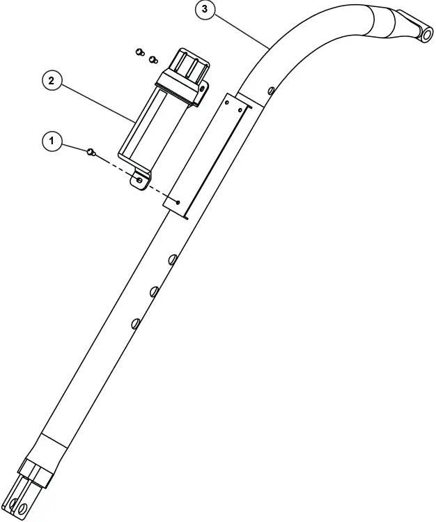
Remove the manual and hardware pack from the manual canister 2. Attach manual canister 2 on the boom 3 using hex bolt M8 X 16 X 1.25mm 1.
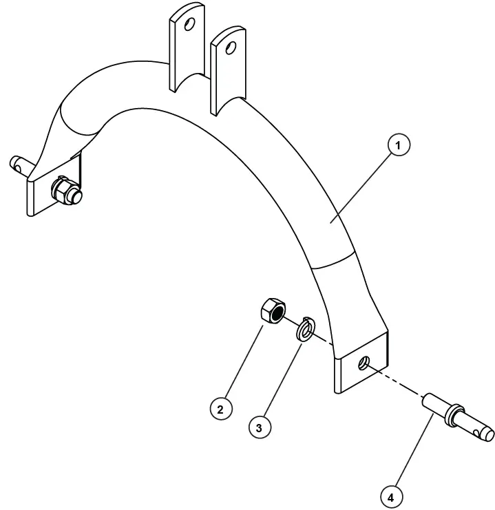
- STEP 3:
Attach the 7/8” lock washer 3 , 7/8” hex nut 2 , draw pin 4 to the “A” frame 5. For the model 650 digger, Category 1 tractors (lift arm spacing of 26”), use the pins in the inward position. For Category 2 tractors (lift arm spacing of 32”), the pins should point outwards.
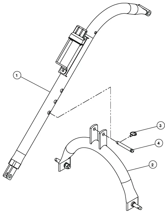
- STEP 4:
Connect the “A” frame assembly 2 to the tractor’s 3-point lift arms. Attach the boom assembly 1 to the tractor. Attach the “A” frame 2 to the boom 1 using the pin 3 and lynch pin 4 The size of your tractor and auger will determine which hole will work best for the angle adjustment. After complete assembly the “A” frame to boom location might need to be changed, with the tractor lift arms raised the auger should be no more than 6″ off the ground.
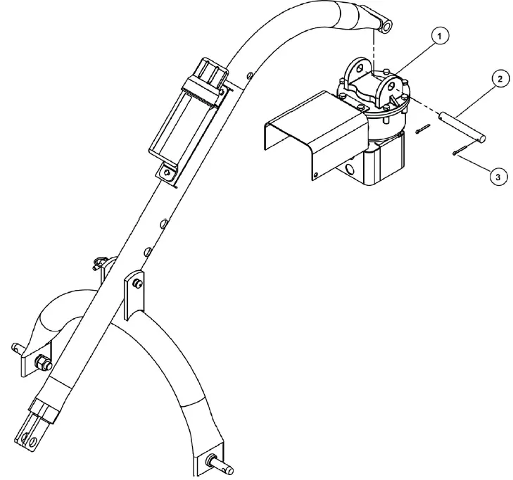
- STEP 5:
Attach the gear box 1 to the boom using the boom pin 2 and secure with cotter pins 3
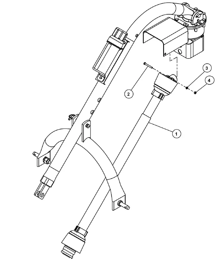
- STEP 6:
Attach the driveline 1 to the gear box input shaft using the hex bolt 3/8” x 3″ G5 2 , 3/8” lock washer 3 and 3/8”-16 hex nut 4. Insert the ¼”x 3/8” set screw in the hole on the yoke that aligns with the 3/16” groove on the gear box input shaft. Tighten loosely.
Attach the tractor end of the driveline 1 to the tractor PTO shaft. Retract the yellow zinc plated outer collar and slip it on the splined PTO shaft of the tractor. Release the collar when it is securely in place on the shaft. The driveline has 1-3/8×6 spline for tractor end. PTO adaptors or extenders are not recommended.
ATTENTION:
THE HEX BOLT 3/8″-16 X 3″ G5 2 PROVIDES SHEAR PROTECTION. USE A GRADE 2 OR GRADE 5 BOLT ONLY TO AVOID DAMAGE TO THE GEAR BOX OR AUGER.
IMPORTANT:
The universal joint should be greased with a quality grade chassis lube approximately every 6 months. At the beginning of each season grease the sliding driveshaft members with a moly grease. All diggers are equipped with quick-detach universal joints on the power-take-off end for a 1-3/8 in. splined shaft.
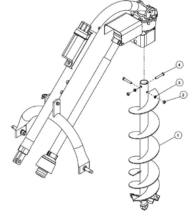
- STEP 7:
Attach the auger 1 to the output shaft on the bottom of the gear box using the hex bolts 1/2″-13×3″ 4 , ½” lock washer 3 and ½” hex nut 2 . Tighten the hardware.
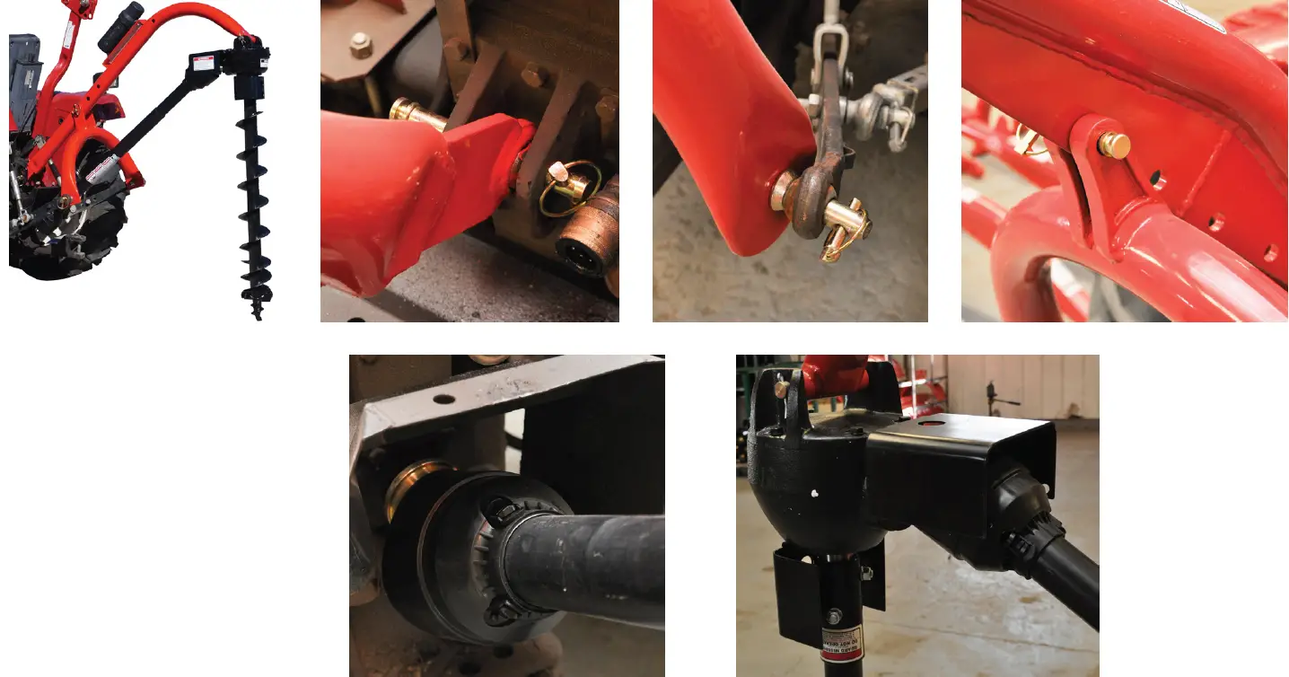
NOTE:
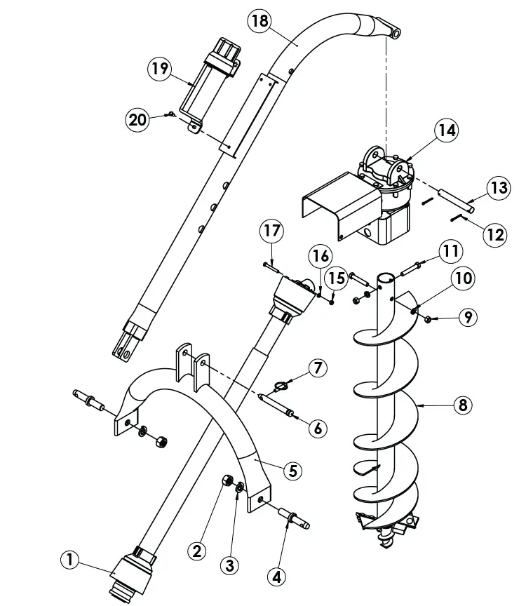
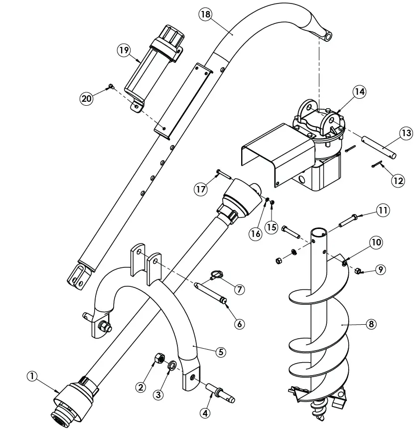
- See the images below for reference in assembling the digger and mounting it to the tractor.
- If the 7/8 in. diameter draw pins in the “A” frame are too small for the holes in the lift arms a Cat 1 to Cat 2 draw pin can be substituted or bushings should be used to obtain the proper fit.

OPERATING INSTRUCTIONS
WARNING:
Read and thoroughly understand all instructions and safety information before assembling or operating this post hole digger. Failure to do so may cause serious injury or death.
- STEP 1:
After attaching the post hole digger to the tractor, before engaging the power, slowly lower the auger to the ground at the desired angle for hole digging. - STEP 2:
Engage the power take off and start digging at a slow speed lowering the auger slowly as the hole is dug. - STEP 3:
Increase the speed as the auger goes deeper into the ground. The type of soil will determine the proper auger speed. A very hard or compacted soil may require operation at varying speeds to be the most efficient in digging.
NEVER ALLOW THE TRACTOR’S ENGINE TO RUN WHILE MANUALLY DISLODGING AN OBSTACLE.
If a rock or other obstacle is encountered that is too large for the auger to displace the post hole digger will begin to vibrate. Slowly withdraw the auger from the hole completely. Turn off the tractor’s power and remove the obstacle manually. Slowly lower the auger into the hole and engage the power to complete digging the hole. - STEP 4:
After the desired hole depth has been reached, spin the auger at a high speed to clear the hole of soil. Reduce the speed before withdrawing the auger from the hole. - STEP 5:
Disengage the power take off after withdrawing the auger from the hole and move to the next desired hole location.
MAINTENANCE
WARNING;
- ALWAYS PERFORM MAINTENANCE OPERATIONS WITH THE TRACTOR’S ENGINE POWERED OFF, PTO DISENGAGED, AND THE AUGER TIP RESTING ON THE GROUND.
- Before operation check all safety shields. Replace shields that are worn or broken before operating the post hole digger.
- When the self-sharpening points on the auger show excessive wear it is important to replace them.
- Check the oil level after every 50 hours of operation. Use EP90 lubricant or equivalent and fill to oil level plug. Always use the same replacement lubricant type.
- Universal joints should be greased with chassis lube once a week during operating season. Grease the sliding drive shaft members with moly grease at the beginning of each season.
- To remove the auger from the gear box output shaft, remove the two 1/2 in. x 3 in. hex cap screws.
- To remove the drive shaft from the gear box input shaft, remove the shear pin bolt and 1/4 in. set screw.
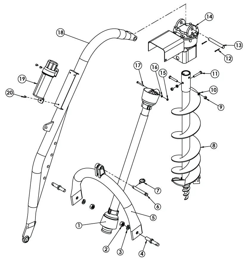
POST HOLE DIGGER PARTS LIST
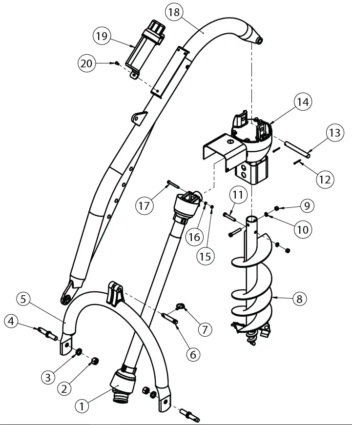
| MODEL 1500 POST HOLE DIGGER | |||
| ITEM # | P/N | DESCRIPTION | QTY |
| 1 | 27-023 | SERIES 4 DRIVELINE | 1 |
| 2 | 95462A545 | 7/8”- 14 HEX NUT | 2 |
| 3 | 91102A037 | 7/8” LOCK WASHER | 2 |
| 4 | 43-027 | 7/8” DRAW PIN | 2 |
| 5 | 24-0358 | MODEL 1500 A-FRAME | 1 |
| 6 | 24-0029 | A-FRAME PIN | 1 |
| 7 | 43-047 | 7/16” LYNCH PIN | 1 |
| 8 | N/A | AUGER (VARIOUS SIZES) | 1 |
| 9 | 95462A033 | 1/2”-13 HEX NUT | 2 |
| 10 | 91102A770 | 1/2”-13 LOCK WASHER | 2 |
| 11 | 91247A724 | 1/2”-13 X 3” G5 BOLT | 2 |
| 12 | 98338A230 | 5/32” X 1-1/2” COTTER PIN | 2 |
| 13 | 24-0028 | BOOM PIN | 1 |
| 14 | 24-0360 | 75 HP GEARBOX WITH GUARDS | 1 |
| 15 | 95462A031 | 3/8” -16 HEX NUT | 1 |
| 16 | 91102A760 | 3/8” LOCK WASHER | 1 |
| 17 | 91247A636 | 3/8”-16 X 3” BOLT, G5 | 1 |
| 18 | 24-0357 | MODEL 1500 BOOM | 1 |
| 19 | 24-0014 | MANUAL CANISTER | 1 |
| 20 | 92865A581 | BOLT, 5/16”-18 X 3/4”, SHCS | 3 |
MODEL 1000 POST HOLE DIGGER | |||
| ITEM # | P/N | DESCRIPTION | QTY |
| 1 | 27-023 | SERIES 4 DRIVELINE | 1 |
| 2 | 95462A545 | 7/8”- 14 HEX NUT | 2 |
| 3 | 91102A037 | 7/8” LOCK WASHER | 2 |
| 4 | 43-027 | 7/8” DRAW PIN | 2 |
| 5 | 24-0356 | MODEL 1000 A-FRAME | 1 |
| 6 | 24-0029 | A-FRAME PIN | 1 |
| 7 | 43-047 | 7/16” LYNCH PIN | 1 |
| 8 | N/A | AUGER (VARIOUS SIZES) | 1 |
| 9 | 95462A033 | 1/2”-13 HEX NUT | 2 |
| 10 | 91102A770 | 1/2”-13 LOCK WASHER | 2 |
| 11 | 91247A724 | 1/2”-13 X 3” G5 BOLT | 2 |
| 12 | 98338A230 | 5/32” X 1-1/2” COTTER PIN | 2 |
| 13 | 24-0028 | BOOM PIN | 1 |
| 14 | 24-0359 | 45HP GEARBOX WITH GUARDS | 1 |
| 15 | 95462A031 | 3/8” -16 HEX NUT | 1 |
| 16 | 91102A760 | 3/8” LOCK WASHER | 1 |
| 17 | 91247A636 | 3/8”-16 X 3” BOLT, G5 | 1 |
| 18 | 24-0316 | MODEL 1000 BOOM | 1 |
| 19 | 24-0014 | MANUAL CANISTER | 1 |
| 20 | 92865A581 | BOLT, 5/16”-18 X 3/4”, SHCS | 3 |
MODEL 650 POST HOLE DIGGER | |||
| ITEM # | P/N | DESCRIPTION | QTY |
| 1 | 27-024 | SERIES 1 DRIVELINE | 1 |
| 2 | 95462A545 | 7/8”- 14 HEX NUT | 2 |
| 3 | 91102A037 | 7/8” LOCK WASHER | 2 |
| 4 | 43-027 | 7/8” DRAW PIN | 2 |
| 5 | 24-0370 | MODEL 650 A-FRAME | 1 |
| 6 | 24-0029 | A-FRAME PIN | 1 |
| 7 | 43-047 | 7/16” LYNCH PIN | 1 |
| 8 | N/A | AUGER (VARIOUS SIZES) | 1 |
| 9 | 95462A033 | 1/2”-13 HEX NUT | 2 |
| 10 | 91102A770 | 1/2”-13 LOCK WASHER | 2 |
| 11 | 91247A724 | 1/2”-13 X 3” G5 BOLT | 2 |
| 12 | 98338A230 | 5/32” X 1-1/2” COTTER PIN | 2 |
| 13 | 24-0028 | BOOM PIN | 1 |
| 14 | 24-0359 | 45 HP GEARBOX WITH GUARDS | 1 |
| 15 | 95462A031 | 3/8” -16 HEX NUT | 1 |
| 16 | 91102A760 | 3/8” LOCK WASHER | 1 |
| 17 | 91247A636 | 3/8”-16 X 3” BOLT, G5 | 1 |
| 18 | 24-0371 | MODEL 650 BOOM | 1 |
| 19 | 24-0014 | MANUAL CANISTER | 1 |
| 20 | 92865A581 | BOLT, 5/16”-18 X 3/4”, SHCS | 3 |
MODEL 400 POST HOLE DIGGER | |||
| ITEM # | P/N | DESCRIPTION | QTY |
| 1 | 27-024 | SERIES 1 DRIVELINE | 1 |
| 2 | 95462A545 | 7/8”- 14 HEX NUT | 2 |
| 3 | 91102A037 | 7/8” LOCK WASHER | 2 |
| 4 | 43-027 | 7/8” DRAW PIN | 2 |
| 5 | 24-0016 | MODEL 400 A-FRAME | 1 |
| 6 | 24-0029 | A-FRAME PIN | 1 |
| 7 | 43-047 | 7/16” LYNCH PIN | 1 |
| 8 | N/A | COMPACT AUGER (VARIOUS SIZES) | 1 |
| 9 | 95462A033 | 1/2”-13 HEX NUT | 2 |
| 10 | 91102A770 | 1/2”-13 LOCK WASHER | 2 |
| 11 | 91247A724 | 1/2”-13 X 3” G5 BOLT | 2 |
| 12 | 98338A230 | 5/32” X 1-1/2” COTTER PIN | 2 |
| 13 | 24-0028 | BOOM PIN | 1 |
| 14 | 24-0359 | 45 HP GEARBOX WITH GUARDS | 1 |
| 15 | 95462A031 | 3/8” -16 HEX NUT | 1 |
| 16 | 91102A760 | 3/8” LOCK WASHER | 1 |
| 17 | 91247A636 | 3/8”-16 X 3” BOLT, G5 | 1 |
| 18 | 24-0015 | MODEL 400 BOOM | 1 |
| 19 | 24-0014 | MANUAL CANISTER | 1 |
| 20 | 92865A581 | BOLT, 5/16”-18 X 3/4”, SHCS | 3 |
WARRANTY
IMPORTANT NOTICE
We, the manufacturer, reserve the right to change the product and/ or specifications in this manual without notification. The manual is for information use only and the pictures and drawings depicted herein are for reference only.
Warranty Repair and Service
Do not return this product to the store for warranty issues or repair. Call our customer service department at 303-278-0664 for the location of the nearest service center.
Record the information below for future reference.
Model No. ___________________________________________________________________
Serial No. (found on boom) ______________________________________________________
Date of Purchase_______________________________________________________________
Place of Purchase_______________________________________________________________
SPECIFICATIONS
SKU/Part No. | 24-0361 | 24-0362 | 24-0318 | 24-0337 |
| Model # | 400 | 650 | 1000 | 1500 |
| Description | Compact | Standard Duty | Light/Heavy Duty | Heavy Duty |
| Tractor Category | Subcompact and CAT 0 | CAT 1 and CAT 2 | CAT 1 and CAT 2 | CAT 1 and CAT 2 |
| Gear Box | 2.9:1 Ratio, 2″ output shaft | 2.9:1 Ratio, 2″ output | 2.9:1 Ratio, 2″ output | 3:1 Ratio, 2″ output shaft |
| Driveline | Series 1, fits 6-spine PTO | Series 1, fits 6-spine PTO | Series 4, fits 6-spine PTO | Series 4, fits 6-spine |
| Boom | 2-7/8″ OD tubing | 2-7/8″ OD tubing | 2-7/8″ OD tubing | 3-1/2″ OD Tubing |
| A-Frame | 2-7/8″ OD tubing | 2-7/8″ OD tubing | 2-7/8″ OD tubing | 3-1/16″ OD tubing |
| Safety Shields | On driveline, gear box “U” joint and gear box output shaft | |||
| Shear Bolt | Replaceable | |||
| Augers | 6″ diameter compact auger | 6″ diameter auger | 6″ diameter auger | 6″ diameter auger |
| 9″ diameter compact auger | 9″ diameter auger | 9″ diameter auger | 9″ diameter auger | |
| 12″ diameter compact auger | 12″ diameter auger | 12″ diameter auger | 12″ diameter auger | |
| – | – | 18″ diameter auger | 18″ diameter auger | |
| – | – | 24″ diameter auger | 24″ diameter auger | |
| Warranty | 1 Year Limited Warranty | 1 Year Limited Warranty | 1 Year Limited Warranty | 1 Year Limited Warranty |
REGISTRATION
Acceptance of responsibility:
I (purchaser) have read the Operation Manual and Limited Warranty or someone has read and explained all instructions to me. I understand this warranty does not cover any labor and that all disputes will be settled by binding arbitration. Warranty void if any attempt to repair or replace defective parts has been made by unauthorized personnel. The mark next to each item below confirms my acceptance of responsibility for the use and maintenance of this post hole digger. I understand that I alone am responsible for the proper maintenance, care and safe operation of this post hole digger.
- Received, read and understand the Operation Manual
- Understand the safety warnings
- Specifications accepted
- Operations understood
- Maintenance requirements understood
I (purchaser) understand that persons who have not read and understand the operations manual should not be allowed to use the machinery. Children should not operate or be near the equipment. Anyone operating the post hole digger must have read the safety and operations manual.
Is this post hole digger used in a business:
No: ______________ Yes, business type: ______________
Owner / Purchaser Signature: ________________________________________________________
The warranty may be refused if the registration is not legible, completed and signed. It is the responsibility of the purchaser to assure that the registration form is received.
Agknx product warranty offers one year warranty against workmanship.
The warranty gives the consumer certain and specific rights which may vary from state to state.
Warranty does not cover normal wear, misuse, neglect, abuse, improper maintenance, overload beyond rated capacity, accidents, cosmetic defects, consumables, non-authorized replacement parts or accessories, operation with inadequate supply of gear box oil, improper fluid types or unauthorized adjustments.
WARRANTY VOID IF REGISTRATION IS NOT POST MAKED WITHIN 15 DAYS OF PURCHASE.
Mail to:
AGKNX
15000 West 44th Ave, Suite B
Golden, CO 80403
Serial #: ________________________________________________________________________________
Purchase Date: __________________________________________________________________________
Purchased From: ________________________________________________________________________
Purchaser: _____________________________________________________________________________
Purchaser’s Address: ____________________________________________________________________
City: _________________________ State: _______________________ Zip Code: __________________
Phone:________________________ Email: ___________________________________________________
Attach a copy of receipt or proof of purchase.
Registration may be completed by scanning the Registration pages and emailing them to: [email protected]


